成形极限图(forming limit diagram,FLD)是定量评价金属板料在加工制造过程中成形性能的重要工具,可以快速直观地判断其在不同应变路径下发生颈缩或破裂的可能性[1 ] 。由于实验获得FLD需要花费大量的时间和经济成本,几十年来众多学者提出了丰富的理论方法来分析应变局部化和预测FLD,其中应用最为广泛的是Marciniak和Kuczyński (M-K)[2 ] 提出的凹槽理论,他们认为板料厚度的非均匀性是造成颈缩区应变局部化的本质原因。随后,科研人员将各类本构方程、屈服函数、硬化模型和断裂准则嵌入到M-K模型中来预测不同材料在不同变形条件下的极限应变[3 ] 。
近年来,随着微观组织表征技术和高效计算技术的发展,能够从微观本质上反映材料各向异性变形行为的晶体塑性(crystal plasticity,CP)模型逐渐成为研究热点[4 ] 。除了用于分析材料复杂的变形机制、力学响应及组织/织构演化规律之外,一些学者尝试将CP模型与M-K理论结合来评估金属板料的FLD。Kim等[5 ] 提出了一种耦合晶体塑性有限元(crystal plasticity finite element,CPFE)模型和M-K理论的多尺度方法,准确预测了铁素体不锈钢的FLD。Bong等[6 ] 和蔡旺等[7 ] 采用类似的方法分别预测了镁合金板和孪生诱发塑性(TWIP)钢板的成形极限。Nagra等[8 ] 将基于快速Fourier变换(FFT)的CP模型和M-K理论结合研究了晶粒尺寸和形状对FLD的影响。近期,Li等[9 ] 通过耦合黏塑性自洽(viscoplastic self-consistent,VPSC)模型和M-K方法分析了动态再结晶和预应变对AZ31B镁合金板高温成形极限的影响。然而,目前从细观尺度上预测钛合金高温成形极限的研究还很有限。而且,现有的理论模型中均没有考虑变形过程中的材料损伤,而损伤演化与材料力学性能密切相关,进而会对成形极限的预测精度产生不容忽视的影响。
本工作以近α 型TA32钛合金板材为研究对象,基于实际晶粒形貌和晶体取向建立了考虑位错密度的CPFE模型,并将基于累积塑性应变能的微孔洞形核准则嵌入到CPFE模型中,分析了不同应变路径下材料的损伤演化行为。同时,建立了CPFE和M-K理论的耦合模型,对TA32板材的高温成形极限进行了理论预测,并通过Nakazima热冲压实验验证了CPFE-M-K耦合模型预测FLD的准确性。
1 实验方法
1.1 材料与组织表征
实验材料为1.5 mm厚TA32钛合金板,名义成分为Ti-5.5Al-3.5Sn-3.0Zr-0.7Mo-0.3Si-0.4Nb-0.4Ta (质量分数,%),相变点约为1000 ℃[10 ] 。采用Supra 55 SAPPHIRE型扫描电子显微镜(SEM)对TA32板材的微观组织进行电子背散射衍射(EBSD)表征,并通过Channel 5软件对EBSD数据进行分析处理。
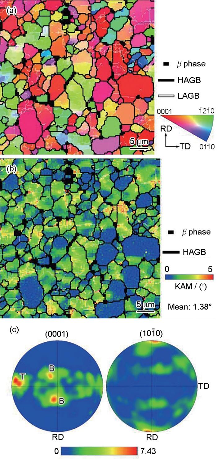
钛合金薄壁件的传统热成形温度一般在900 ℃左右,较高的成形温度常导致晶粒粗化、表面氧化和力学性能弱化。为了节约能耗和提高成形构件服役性能,本工作将研究温度设为750 ℃。参考钛合金板材热成形时的保温时间,将原始板材在750 ℃下保温15 min后的微观组织作为热变形的初始状态。图1a 显示了轧向(RD)和横向(TD)构成平面上的反极图,其中黑线代表大角度晶界(HAGBs,> 15°),白线代表小角度晶界(LAGBs,2°~15°),不同颜色代表α 相的晶粒取向,黑色区域代表β 相。TA32合金主要由等轴状α 相和少量晶间β 相构成。图1b 为初始组织的局部取向差(KAM)分布图。大多数α 晶粒的KAM值较高,从侧面反映出板材内部具有较高的平均位错密度,平均取向差约为1.38°。根据Kumar等[11 ] 的研究,板料中的几何必需位错(GND)密度可通过ρ GND = 2ϑ / (nb )近似得到,其中ϑ 为平均取向差(弧度制),n 为EBSD扫描步长(本工作取0.3 μm),b 为α 相的Burgers矢量模(本工作取2.95 × 10⁻¹⁰ m)。将ρ GND 近似代替为整体位错密度,计算得到初始位错密度约为5.45 × 10¹⁴ m-2 。图1c 显示了初始组织的(0001)和(10 1 ¯ 0 ) 极图。可以看出,TA32板材中主要包含横向织构和基面双峰织构,分别用“T”和“B”进行标记。
图1
图1
初始组织的EBSD结果
Fig.1
Electron backscatter diffraction (EBSD) results of the initial microstructure (Transverse texture and basal bimodal texture are marked by T and B, respectively; the same in figures below. HAGB—high-angle grain boundary, LAGB—low-angle grain boundary, RD—rolling direc-tion, TD—transverse direction)
(a) inverse pole figure
(b) kernel average misorientation (KAM) map
(c) pole figure
1.2 单轴拉伸实验
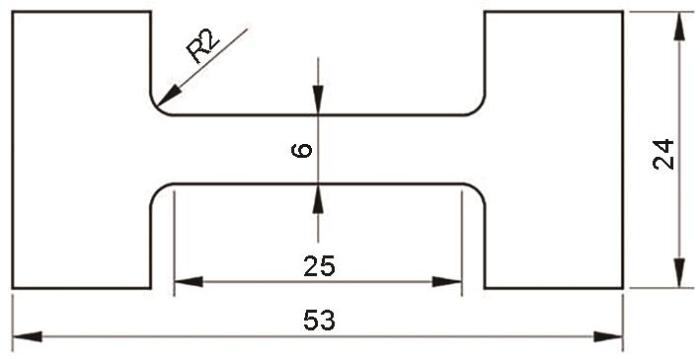
采用SUNS-UTM5504X型高温拉伸试验机在750 ℃和0.001~0.1 s-1 应变速率范围内开展高温单轴拉伸实验。拉伸试样尺寸如图2 所示,符合ASTM E8标准,标距段尺寸为25 mm × 6 mm × 1.5 mm。采用DK7780线切割机床沿RD加工拉伸试样,并用400和1000号砂纸打磨试样表面后喷涂高温防氧化剂,以减少高温氧化对实验结果的不利影响。当加热炉达到目标温度后,将试样迅速放入拉伸夹具中并保温15 min使温度均匀。随后进行单轴拉伸实验,并实时记录夹具的载荷和位移。采用MR5000型金相显微镜对变形后试样的微观组织进行观察。
图2
图2
拉伸试样尺寸
Fig.2
Tensile specimen size (unit: mm)
1.3 成形极限实验
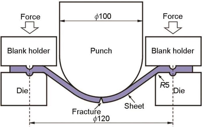
通过在自主研发的高温冲压平台上开展经典的Nakazima实验获得了TA32板材在750 ℃下的FLD,测试装置、实验方法和试样尺寸参见文献[12 ]。Nakazima实验示意图如图3 所示。为了测量变形试样的应变分布,采用RB-1打标机在试样表面电刻蚀了边长为5 mm的方形网格。采用直径为100 mm的半球形冲头以50 mm/min的冲压速率使试样变形(有限元仿真表明该冲压速率下试样顶点处的应变速率接近0.01 s-1 ),直至机床载荷因试样颈缩破裂而降低时立即终止实验。通过多次测量破裂区域附近颈缩网格的尺寸,计算得到不同应变路径下的极限应变点。
图3
图3
Nakazima实验示意图
Fig.3
Schematic of Nakazima test (unit: mm)
2 理论模型
2.1 有限元模型
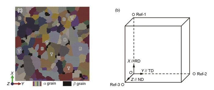
基于图1 的EBSD表征结果,采用Dream.3D开源软件构建了具有真实晶粒形貌和晶体取向的代表性体积单元(representative volume element,RVE),如图4a 所示,其中α 晶粒和β 晶粒分别用彩色网格和黑色网格表示。RVE边长为28 μm,由53562个六面体网格构成,厚度方向设置三层网格,网格类型为C3D8R。通过编写Python脚本将从EBSD数据中提取的晶体取向分配给每个单元。为了便于后续分析材料的变形行为,在图4a 中分别用“T”和“B”标记出了5个代表横向织构的晶粒和5个代表基面织构的晶粒。同时,对RVE施加了三维周期性边界条件(periodic boundary conditions,PBCs)以近似模拟连续的区域,如图4b 所示。PBCs将2个相对表面上的节点位移联系起来并强制其发生相同的变形。通过在ABAQUS的input文件中添加“*equation”关键字来设置顶面(X +)和底面(X -)、右面(Y +)和左面(Y- )以及正面(Z +)和背面(Z -)的约束方程,如 式(1)所示[13 ] :
u i X + = u i X - + u i R e f - 1 u i Y + = u i Y - + u i R e f - 2 u i Z + = u i Z - + u i R e f - 3 (1)
式中,上标表示指定面上的节点,ui (i = 1, 2, 3)表示节点的自由度,Ref-1、Ref-2和Ref-3对应3个参考点(图4b )。通过在3个参考点上施加位移约束或集中力约束实现RVE的塑性变形。
图4
图4
有限元模型
Fig.4
Finite element model
(a) representative volume element (RVE) (B—basal texture, T—transverse texture)
(b) periodic boundary conditions (PBCs) (ND—normal direction)
2.2 晶体塑性模型
在晶体塑性理论中,晶体材料的塑性变形归因于滑移面上的位错运动,从而将细观变形机制与宏观连续介质力学和运动学联系起来。根据Asaro和Rice[14 ] 的单晶理论,变形梯度张量( F F e )和塑性变形梯度( F p ):
F = F e F p (2)
总体速度梯度( L L e )和塑性变形速度梯度( L p ):
L = L e + L p = F ˙ e F e - 1 + F e F ˙ p F p - 1 F e - 1 (3)
式中,F ˙ e F ˙ p F e F p [15 ] 。因此 L p 可通过对所有滑移系的剪切速率求和获得:
L p = F ˙ p F p - 1 = ∑ i = 1 N γ ˙ i S 0 i = ∑ i = 1 N γ ˙ i d 0 i ⊗ n 0 i (4)
式中,γ ˙ i S 0 i i 的剪切应变率和Schmid张量,d 0 i n 0 i i 的滑移方向和滑移面法向的单位向量,N 为滑移系的数量。在高温变形条件下,钛合金的α 相(hcp晶格)共有30个滑移系被激活,包括3个{0001}<11 2 ¯ 0 a >滑移、3个{10 1 ¯ 0 11 2 ¯ 0 a >滑移、6个{10 1 ¯ 1 11 2 ¯ 0 a >滑移、12个{10 1 ¯ 1 11 2 ¯ 3 c + a >滑移和6个{11 2 ¯ 2 11 2 ¯ 3 c + a >滑移。β 相(bcc晶格)共有48个滑移系被激活,包含12个{110}<111>、12个{112}<111>和24个{123}<111>。
由于位错是承载塑性变形的主要方式,其在外力和热激活的共同作用下不断发生滑移和攀移。采用基于位错密度的率相关流动法则来计算剪切应变率[16 ] :
γ ˙ i = γ ˙ 0 e x p - Q S k B T 1 - τ i - S i τ c r i p q s g n τ i (5)
式中,γ ˙ 0 Q S 为位错滑移激活能,k B 为Boltzmann常数,T 为热力学温度,τi 为滑移系i 的分切应力,Si 为滑移系i 的滑移阻力,τ c r i i 的临界分切应力(CRSS),p 和q 为与应变速率敏感性相关的指数。
根据Taylor模型,滑移阻力主要取决于位错密度,并随着位错运动而不断发生演变,因此硬化模型表示为:
S i = λ μ b ∑ j h i j ρ j (6)
式中,λ 为统计系数,μ 为剪切模量,ρ 为滑移系的位错密度。hij 为位错相互作用矩阵,可分为自硬化(对角线项)和潜硬化(非对角线项)。为了简化计算,hij 可表示为:
h i j = ω 1 + 1 - ω 2 δ i j (7)
式中,ω 1 和ω 2 为相互作用系数,δ i j
本工作采用广泛使用的Kocks-Mecking模型描述变形过程中位错密度的演变ρ ˙ i [17 ] :
ρ ˙ i = γ ˙ i b ∑ j ≠ i ρ j k 1 - k 2 ρ i (8)
式中,等式右侧第一项控制位错大量增殖,第二项控制与动态回复和再结晶相关的位错湮灭。k 1 和k 2 为与温度和应变速率相关的材料常数,可进一步修正为:
k 1 = - l n ε ˙ ⋅ e x p T k 3 (9)
k 2 = - l n ε ˙ ⋅ e x p k 4 T (10)
式中,k 3 和k 4 分别为位错增殖常数和位错湮灭常数,ε ˙
采用Fortran语言编写UMAT材料子程序将CP模型嵌入ABAQUS/Standard软件中来实现CPFE模拟。值得注意的是,α 相和β 相的本构方程是相同的,通过使用不同的滑移系和模型参数来反映变形行为之间的差异性。
2.3 损伤演化模型
钛合金在热变形过程中的损伤累积与失稳断裂主要源自微孔洞的形核、长大和聚合。研究表明微孔洞的形核与等效塑性应变密切相关[18 ] ,同时,局部应力集中也是诱发微孔洞形核的一个重要原因[19 ] 。因此,同时考虑应变和应力作用的累积塑性应变能模型可以用来表征微孔洞的演化行为。Freudenthal[20 ] 于1950年提出的第一个非耦合型韧性断裂准则就是基于应变能的判据。本工作中,微孔洞的能量累积模型可表示为:
D = ∫ σ ¯ d ε ¯ p (11)
式中,D 为累积塑性应变能,σ ¯ ε ¯ p D 值达到临界值时,认为发生了微孔洞形核。D c 是与温度和应变速率相关的微孔洞形核临界值,可进一步表示为:
D c = - l n ε ˙ ⋅ e x p T d 1 (12)
式中,d 1 为损伤相关材料常数,通过拟合不同条件下的应力-应变曲线获得。此外,Zhao等[21 ] 通过将微孔洞单元的强度人为设置为5 MPa,来减小其对整体强度的贡献。但该方法非常容易造成模型计算不收敛。本工作根据连续损伤力学中有效应力的概念,将 式(5)中的τi 替换为损伤修正分切应力(τ D i ) ,描述损伤对材料力学性能的影响:
τ D i = τ i ( D < D c ) τ i 1 - D ' ( D ≥ D c ) (13)
式中,D' 为损伤分数,定义为损伤单元数量占RVE单元总数的比重。
2.4 CPFE 和M-K 耦合模型
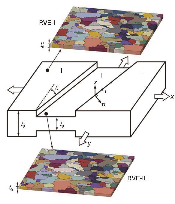
M-K理论假设板料中预先存在一个凹槽缺陷,变形过程中厚度不均匀引起的应变局部化导致了失稳断裂的发生[2 ] 。本工作参考Kim等[5 ] 提出的理论方法,通过耦合CPFE模型与M-K理论来预测板料的成形极限,示意图如图5 所示。板材被分为凹槽外的区域I和凹槽内的区域II。建立了2个具有不同厚度的有限元模型RVE-I和RVE-II,分别用于模拟区域I和区域II的塑性变形。初始缺陷因子(即板厚不均匀度)可表示为f 0 t 0 I I t 0 I t 0 I t 0 I I x 轴和y 轴分别与板料的RD和TD平行,n 轴和l 轴分别表示凹槽的法线和切线方向。凹槽的倾角(θ )定义为y 轴和l 轴所夹的锐角。
图5
图5
晶体塑性有限元(CPFE)-Marciniak-Kuczyński (M-K) (CPFE-M-K)耦合模型预测成形极限图(FLD)的示意图
Fig.5
Schematic of CPFE-M-K coupling model for predicting FLD (CPFE—crystal plasticity finite element, M-K—Marciniak-Kuczyński, FLD—forming limit diagram, t 0 I t 0 I I θ —inclination angle of the groove)
根据M-K理论中的基本假设,凹槽内外的力平衡条件应满足以下关系:
F n n I = σ n n I t I w I = σ n n I I t I I w I I = F n n I I (14)
F n l I = σ n l I t I w I = σ n l I I t I I w I I = F n l I I (15)
式中,F 和σ 表示施加的力载荷和应力,t 和w 表示RVE的厚度和宽度,上标I和II分别表示RVE-I和RVE-II,下标nn 和nl 分别表示凹槽内的正应力和切应力。变形协调条件还要求2个区域沿l 轴方向的应变增量相同,即:
Δ ε l l I = Δ ε l l I I (16)
在变形过程中,全局坐标系(x , y , z )和局部坐标系(n , l , z )中的应力分量(σxx 、σyy 、σxy )和(σnn 、σll 、σnl )及应变增量分量(Δεxx 、Δεyy 、Δεxy )和(Δεnn 、Δεll 、Δεnl )可通过 式(17)进行转换[22 ] :
σ n n = σ x x c o s 2 θ + σ y y s i n 2 θ - 2 σ x y s i n θ c o s θ σ n l = σ y y - σ x x s i n θ c o s θ + σ x y s i n 2 θ - c o s 2 θ Δ ε l l = Δ ε x x s i n 2 θ + Δ ε y y c o s 2 θ + 2 Δ ε x y s i n θ c o s θ (17)
此外,由于在材料内部可能存在任意角度的缺陷,且变形过程中θ 会随着应变的增加不断变化。因此,本工作通过 式(18)对当前倾角θ 进行更新[9 ] :
t a n θ = e x p 1 - ξ ε x x I t a n θ 0 (18)
式中,ξ Δ ε y y I Δ ε x x I Δ ε x x I Δ ε y y I x 轴和y 轴的应变增量;θ 0 为凹槽的初始倾角。
通过CPFE-M-K耦合模型求解TA32板材FLD的具体步骤总结如下。(1) 将特定的ξ f 0 和θ 0 ,基于第(1)步的模拟结果,采用式(14)~(18)得到RVE-B的边界条件(F n n I I F n l I I Δ ε l l I I ) ,并进行RVE-II的CPFE模拟。(3) 采用被广泛使用的成形极限准则(Δ ε ¯ I I ≥ 10 Δ ε ¯ I ) 判断是否发生颈缩破裂,其中Δ ε ¯ I Δ ε ¯ I I ε x x I ε y y I θ 0 (0° ≤ θ 0 ≤ 90°),重复步骤(2)和(3),将计算的最小极限应变作为当前应变路径下的成形极限点。(5) 对不同的加载路径(- 0.5 ≤ ξ ≤ 1.0 ) 重复该程序以获得完整的FLD。
3 结果与讨论
3.1 模型参数校准与验证
CPFE模型中的材料参数很难通过独立实验或仿真直接测量和计算。因此,本工作通过参考相关文献、分析微观组织及拟合力学曲线对各项参数进行标定。通常认为金属材料的弹性模量和剪切模量与温度成反比。根据Alabort等[23 ] 的研究,剪切模量与温度的关系可以表示为:
μ T = μ 0 1 + T - 300 T M T M μ 0 d μ d T (19)
式中,μ 0 为室温剪切模量,T M 为钛合金熔点,T M μ 0 d μ d T α 相和β 相的相应材料参数如表1 [23 ,24 ] 所示。
基于剪切模量,TA32钛合金的高温弹性常数(Cij )可以通过 式(20)近似计算得到:
C i j = C i j 0 μ T μ 0 (20)
式中,Cij 0 为钛合金室温弹性常数,表1 [23 ,24 ] 中列出了α 相和β 相对应的弹性常数。
钛合金不同滑移系的CRSS难以通过实验方法直接获得,参考Zhao等[15 ] 关于TA15钛合金板的研究,近α 钛合金柱面滑移系在750 ℃下的CRSS约为140 MPa。而且,在高温变形过程中,α 相的基面<a >、柱面<a >、锥面<a >和二阶锥面<c + a >滑移系的CRSS之比近似为1∶0.7∶3∶3。由于β 相是具有高对称性的bcc结构,假设β 相各滑移系在高温变形中的CRSS相等,根据Bai等[25 ] 的研究结果,高温下β 相与α 相的屈服应力比约为0.8。因此,假设β 相各滑移系的CRSS为α 相柱面滑移系CRSS的0.8倍。此外,采用MATLAB中的lsqcurvefit函数和ABAQUS有限元仿真对其余材料参数进行迭代优化。表2 中列出了CPFE模型中的材料参数。
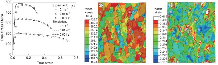
图6a 对比了750 ℃不同应变速率下单轴拉伸实验结果与模拟结果。可以看出,CPFE模型能够较好地描述TA32板材在不同应变速率下的高温流动行为,包括稳态变形阶段和颈缩失稳阶段。图6b 和c 分别显示了以0.01 s-1 应变速率变形至等效应变0.3时的应力云图和应变云图。可以看出,晶粒沿拉伸方向被拉长,且塑性变形在微观尺度上是非均匀的,不同取向晶粒表现出截然不同的力学响应。
图6
图6
CPFE模型单轴拉伸实验结果与模拟结果对比及云图
Fig.6
Uniaxial tensile simulation results from CPFE model
(a) stress-strain curves of experimental and simulated results (b, c) stress nephogram (b) and strain nephogram (c) of RVE deformed to equivalent strain 0.3 at a strain rate of 0.01 s-1
3.2 非均匀变形行为
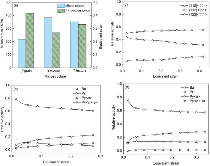
为了深入理解TA32钛合金的损伤演化行为,首先需要对材料的非均匀变形机制展开研究。通过均值化处理,得到了不同取向晶粒的应力和应变分布,如图7a 所示。β 晶粒表现出最低的流动应力和最高的塑性应变;相比于B织构,T织构的应力水平更低,而应变水平更高。Wu等[26 ] 的研究表明,不同晶粒之间的非均匀变形主要归因于晶粒的取向不同,进而导致变形过程中激活的滑移系差异明显。因此,将晶粒中某一族滑移系的剪切应变除以所有滑移系的剪切应变之和定义为该族滑移系的相对活性,用于表征其对塑性变形的相对贡献量。
图7
图7
不同取向晶粒变形行为分析
Fig.7
Analyses of deformation behavior of grains with different orientations (Ba—basal slip, Pr—prismatic slip, Py—pyramidal slip)
(a) stress and strain distributions (b-d) relative activities of slip systems of β grain (b), B texture (c), and T texture (d)
图7b~d 描述了RVE变形至等效应变0.3时,不同晶粒内各族滑移系的相对活性与等效应变之间的关系。对于β 晶粒,由于较高的晶体对称性,在变形过程中三族滑移系同时开动,其中{123}<111>和{112}<111>滑移主导变形,较低的CRSS也使其在变形过程中承受抗力较小,同时容纳更大的塑性应变。对于B织构,变形由锥面<a >滑移系主导,随着应变的增加,锥面<c + a >滑移的相对活性增加,基面滑移的相对活性降低。因此,基面滑移和柱面滑移不活跃是B织构应力水平高、应变水平低的直接原因。对于T织构,主导滑移系为α 相中CRSS最小的柱面滑移,因此其在单轴拉伸时表现出比B织构更好的成形性。随着应变的增加,柱面滑移的占比减少,锥面<c + a >滑移为了协调变形被更多地激活。
3.3 不同应变状态下的损伤演化
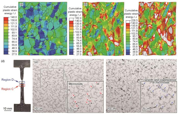
图8a~c 分别显示了RVE以0.01 s-1 应变速率单轴拉伸至等效应变0.1、0.3和0.4时的累积塑性应变能,其中白色区域代表微孔洞。可以看出,微孔洞主要在α /β 相界和晶界的三叉交界处形核。随着变形的进行,微孔数量急剧增加,并在拉应力和切应力的作用下发生长大和聚合,从而导致材料力学性能下降。此外,相比于T织构,B织构更容易诱导孔洞形核。这是由于B织构在变形过程中滑移系开动所需外力更大,更容易引起应力集中。随后,对相同变形条件下拉伸试样的2个不同区域(图8d 中的区域C 和D )进行金相观察,如图8e 和f所示,其中区域C稍微远离断口,区域D靠近断口。TA32合金的微观组织中α 相为基体,大量细小的β 相晶粒弥散分布于α 相之间。图8e 和f 的右下角为局部放大图,其中微孔洞的形核用红色箭头标记,长大和聚合用蓝色箭头标记。可以看出,在高温拉伸过程中,微孔洞形核时的形状接近于球形,这是由于球形能量最低,有利于微孔洞保持稳定。随着变形量的增加,微孔洞明显发生了长大,且微孔洞聚合方向与拉伸方向的夹角约为45°,如图8f 中蓝色虚线所示。可以看出,模型预测的微孔洞演化特征与实验结果基本一致,从而验证了CPFE模型对于预测材料损伤演化行为的准确性。
图8
图8
TA32板材以0.01 s-1 应变速率单轴拉伸时微孔洞的模拟与实验结果
Fig.8
Simulation results by RVE (a-c) and experimental results (d-f) of microvoids under uniaxial tension at a strain rate of 0.01 s-1 (Insets in Figs.8d and e are enlarged views)
(a-c)at the strains of ε = 0.1 (a), ε = 0.3 (b), and ε = 0.4 (c) (d-f) the specimen (d) and microstructures of region C (e) and region D (f) in Fig.8d
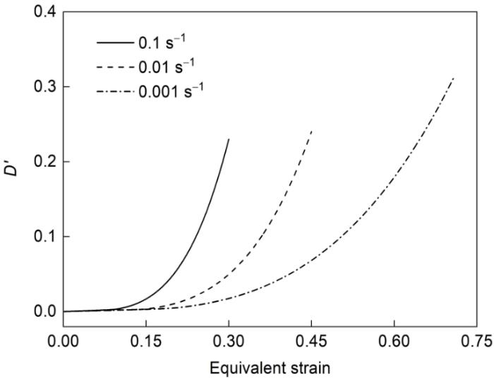
图9 显示了750 ℃不同应变速率下RVE损伤演化的预测结果。在变形初期,由于材料的累计塑性应变能没有达到临界值,损伤分数为零。随着变形量的增加,微孔洞开始在局部形核,且数量不断增加,并发生长大和聚合,导致损伤分数随着应变的增加呈指数关系迅速增长。同时,随着应变速率的降低,损伤增长速率减慢,材料变形能力增强。
图9
图9
RVE损伤分数预测结果
Fig.9
Prediction results of RVE damage fraction (D' )
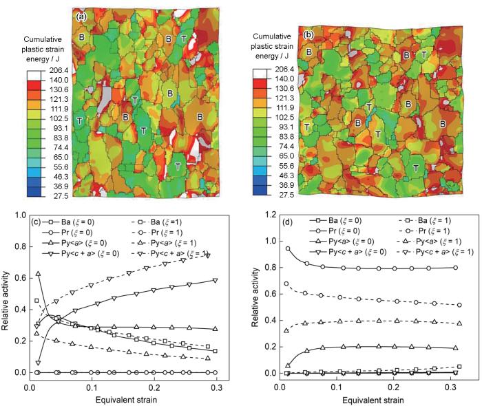
图10a 和b 分别显示了RVE在平面应变和等双轴拉伸路径下以0.01 s-1 应变速率变形至等效应变0.3时的模拟结果,其中白色区域表示微孔洞。在平面应变下,微孔洞主要沿拉伸方向长大和聚合;而在等双轴拉伸路径下,微孔洞由于同时受到沿RD和TD的拉应力而保持球形。图10c 和d 分别显示了B织构和T织构内各族滑移系在平面应变(ξ ξ a >滑移在平面应变路径下被抑制,锥面<c + a >滑移的相对活性逐渐增加并占据主导地位。在等双轴拉伸路径下,锥面<c + a >滑移的相对活性进一步提高,而柱面滑移的作用可忽略不计。由于锥面<c + a >滑移的CRSS最大,这也导致B织构在变形过程中应力较大,容易诱导变形损伤。对于T织构,单轴拉伸时主导变形的柱面滑移在平面应变路径下被进一步增强以协调RVE的整体塑性变形。在等双轴拉伸路径下,锥面<a >滑移的相对活性显著增加以协调沿TD的塑性变形。由于锥面<a >滑移的CRSS高于柱面滑移,所以T织构在等双轴拉伸路径下的累积塑性应变能要高于在平面应变路径下,更容易引起微孔洞的形核。
图10
图10
RVE在750 ℃以0.01 s-1 应变速率变形至等效应变0.3时的模拟结果
Fig.10
Simulation results of RVE deformed to equivalent strain of 0.3
(a, b) damage distributions under plane strain (a) and equi-biaxial tension (b) (c, d) relative activities of slip systems of B texture (c) and T texture (d) (ξ
3.4 成形极限预测
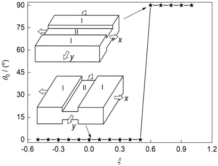
采用M-K理论计算各向异性板材的成形极限时,凹槽初始倾角的改变会显著影响整个应变路径范围的计算结果。图11 显示了不同应变路径下达到最小极限应变时凹槽的临界初始倾角,插图为相应初始倾角的M-K模型示意图。可以看出,当-0.5 ≤ ξ ξ
图11
图11
不同路径下达到最小极限应变时的凹槽临界初始倾角
Fig.11
Critical initial incline angles of groove (θ 0 ) at the minimum limit strain under different strain paths (Insets are M-K models with corresponding initial inclination angles)
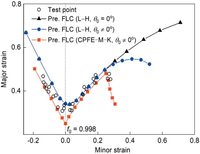
图12 显示了采用不同模型预测的TA32板材在750 ℃和0.01 s-1 条件下的FLD,并将预测结果与Nakazima实验结果进行了对比。其中,空心圆代表试样颈缩点,黑线为作者前期工作中[12 ] 耦合Logan-Hosford (L-H)屈服准则和未考虑凹槽角度变化的M-K模型计算的成形极限曲线(forming limit curve,FLC),蓝线为基于文献[11 ]中的工作,耦合L-H屈服准则和考虑凹槽角度变化的M-K模型计算的FLC,红线为本工作中采用CPFE-M-K耦合模型预测的FLC。FLC随着f 0 的增大而升高,在本工作中f 0 取0.998时整体预测精度最高。从图12 可以看出,当应变路径-0.5 ≤ ξ ξ ξ ξ
图12
图12
750 ℃下实验与预测FLD的对比
Fig.12
Comparison of experimental and predicted FLDs at 750 o C (FLC—forming limit curve, L-H—Logan-Hosford yield function; f 0 —initial imperfection factor)
Signorelli等[27 ] 、Cyr等[28 ] 和Wang等[29 ] 均报道了等双轴拉伸区域极限主应变降低的现象,但均未对此进行解释。Wu等[26 ] 研究发现TA32板材的高温力学性能具有强烈的各向异性,相比于RD,其在TD的流动应力更高,塑性更差。因此,当板料受到的ξ ξ
4 结论
(1) 提出了一种考虑损伤演化的晶体塑性有限元模型,准确地预测了TA32钛合金板材在750 ℃不同应变速率下的宏观力学响应、微观非均匀变形和损伤演化行为。变形行为和损伤演化的差异主要归因于不同取向晶粒激活的滑移系不同。
(2) 不同应变路径下,原始板材中的基面织构比横向织构更容易造成损伤,这是由于该取向晶粒的基面滑移和柱面滑移在变形过程中均被抑制所致。
(3) CPFE-M-K耦合模型中凹槽初始倾角会显著影响TA32板材成形极限的预测精度,应变增量比为-0.5~0.5和0.6~1.0范围内的临界初始倾角分别为0°和90°。
(4) CPFE-M-K耦合模型准确地捕捉了TA32板材在750 ℃下的成形极限,等双轴拉伸区域附近极限主应变的降低与材料力学性能的各向异性密切相关。
参考文献
View Option
[1]
Paul S K Controlling factors of forming limit curve: A review
[J]. Adv. Ind. Manuf. Eng. , 2021 , 2 : 100033
[本文引用: 1]
[2]
Marciniak Z Kuczyński K Limit strains in the processes of stretch-forming sheet metal
[J]. Int. J. Mech. Sci. , 1967 , 9 : 609
[本文引用: 2]
[3]
Banabic D Kami A Comsa D S et al Developments of the Marciniak-Kuczynski model for sheet metal formability: A review
[J]. J. Mater. Process. Technol. , 2021 , 287 : 116446
[本文引用: 1]
[4]
Fan R L Wu Y Chen M H et al Prediction of anisotropic deformation behavior of TA32 titanium alloy sheet during hot tension by crystal plasticity finite element model
[J]. Mater. Sci. Eng. , 2022 , A843 : 143137
[本文引用: 1]
[5]
Kim J H Lee M G Kang J H et al Crystal plasticity finite element analysis of ferritic stainless steel for sheet formability prediction
[J]. Int. J. Plast. , 2017 , 93 : 26
[本文引用: 2]
[6]
Bong H J Lee J Hu X H et al Predicting forming limit diagrams for magnesium alloys using crystal plasticity finite elements
[J]. Int. J. Plast. , 2020 , 126 : 102630
[本文引用: 1]
[7]
Cai W Qian L Y Sun C Y et al Prediction of forming limit of TWIP steel sheet based on CPFE-MK model
[J]. J. Plast. Eng. , 2021 , 28 (6 ): 53
DOI
[本文引用: 1]
A finite element model of the plastic deformation process of TWIP steel sheet coupled with crystal plasticity and MK theory was established. The representative volume elements( RVE) with different thicknesses were used to describe the initial thickness unevenness of MK theory in this model. Crystal plastic constitutive relations coupled with slip and twin were introduced into RVE to describe the microscopic mechanism of plastic deformation of TWIP steel,and the combination of crystal plasticity finite element( CPFE) and MK theory was realized,which was used to reflect the uneven deformation degree of sheet metal and predict the forming limit curve. The simulation results were compared with the experimental forming limit curves of TWIP steel sheet,and the correctness of the model was verified.The effects of initial texture,initial thickness unevenness and initial angle of groove on forming limit of TWIP steel sheet were analyzed using this model. The results show that the formability of the copper type texture is better and the forming limit strain increases with the increase of initial thickness unevenness and the decrease of initial angle of groove.
蔡 旺 , 钱凌云 , 孙朝阳 等 基于CPFE-MK模型的TWIP钢板成形极限预测
[J]. 塑性工程学报 , 2021 , 28 (6 ): 53
[本文引用: 1]
[8]
Nagra J S Brahme A Mishra R et al An efficient full-field crystal plasticity-based M-K framework to study the effect of 3D microstructural features on the formability of polycrystalline materials
[J]. Modell. Simul. Mater. Sci. Eng. , 2018 , 26 : 075002
[本文引用: 1]
[9]
Li Z H Zhou G W Li D Y et al Forming limits of magnesium alloy AZ31B sheet at elevated temperatures
[J]. Int. J. Plast. , 2020 , 135 : 102822
[本文引用: 2]
[10]
Wang Q J Liu J R Yang R High temperature titanium alloys: Status and perspective
[J]. J. Aeronaut. Mater. , 2014 , 34 (4 ): 1
[本文引用: 1]
王清江 , 刘建荣 , 杨 锐 高温钛合金的现状与前景
[J]. 航空材料学报 , 2014 , 34 (4 ): 1
DOI
[本文引用: 1]
简要回顾国内外固溶强化型高温钛合金材料的发展历史,分析英、美、俄等国的高温钛合金研究与应用情况及发展趋势。介绍国内自主研制、使用温度在550~650℃范围内的三种钛合金新材料及其相关技术发展,对国内高温钛合金材料进行初步梳理。参考国外高温钛合金研究、应用经验及发展趋势,结合国内实际情况,对国内高温钛合金材料体系的建立及完善提出具体建议,并展望国内高温钛合金近期研究重点和未来发展方向。
[11]
Kumar S S S Pavithra B Singh V et al Tensile anisotropy associated microstructural and microtextural evolution in a metastable beta titanium alloy
[J]. Mater. Sci. Eng. , 2019 , A747 : 1
[本文引用: 2]
[12]
Fan R L Chen M H Wu Y et al Prediction and experiment of fracture behavior in hot press forming of a TA32 titanium alloy rolled sheet
[J]. Metals , 2018 , 8 : 985
[本文引用: 2]
[13]
Zhang C Xu X W Mao C J Progressive damage simulation and strength prediction of 3D braided composites
[J]. Acta Mater. Compos. Sin. , 2011 , 28 (2 ): 222
[本文引用: 1]
张 超 , 许希武 , 毛春见 三维编织复合材料渐进损伤模拟及强度预测
[J]. 复合材料学报 , 2011 , 28 (2 ): 222
[本文引用: 1]
[14]
Asaro R J Rice J R Strain localization in ductile single crystals
[J]. J. Mech. Phys. Solids , 1977 , 25 : 309
[本文引用: 1]
[15]
Zhao J Lv L X Liu G et al Analysis of deformation inhomogeneity and slip mode of TA15 titanium alloy sheets during the hot tensile process based on crystal plasticity model
[J]. Mater. Sci. Eng. , 2017 , A707 : 30
[本文引用: 2]
[16]
Busso E P Meissonnier F T O'Dowd N P Gradient-dependent deformation of two-phase single crystals
[J]. J. Mech. Phys. Solids , 2000 , 48 : 2333
[本文引用: 1]
[17]
Kocks U F Mecking H Physics and phenomenology of strain hardening: The FCC case
[J]. Prog. Mater. Sci. , 2003 , 48 : 171
[本文引用: 1]
[18]
Hu Q Zhang F F Li X F et al Overview on the prediction models for sheet metal forming failure: Necking and ductile fracture
[J]. Acta Mech. Solida Sin. , 2018 , 31 : 259
[本文引用: 1]
[19]
Wu D Liu L B Zhang L G et al Tensile deformation mechanism and micro-void nucleation of Ti-55531 alloy with bimodal microstructure
[J]. J. Mater. Res. Technol. , 2020 , 9 : 15442
[本文引用: 1]
[20]
Freudenthal A M The Inelastic Behavior of Engineering Materials and Structures [M]. New York : Wiley , 1950 : 128
[本文引用: 1]
[21]
Zhao J Wang K H Lv L X et al Analysing the interaction between microscopic deformation, microstructure and void evolution of near-α titanium alloys during non-superplastic hot deformation by an integrated crystal plasticity finite element model
[J]. Materials , 2022 , 15 : 294
[本文引用: 1]
[22]
Hu Q Li X F Chen J New robust algorithms for Marciniak-Kuczynski model to calculate the forming limit diagrams
[J]. Int. J. Mech. Sci. , 2018 , 148 : 293
[本文引用: 1]
[23]
Alabort E Kontis P Barba D et al On the mechanisms of superplasticity in Ti-6Al-4V
[J]. Acta Mater. , 2016 , 105 : 449
[本文引用: 5]
[24]
Kim J Y Rokhlin S I Determination of elastic constants of generally anisotropic inclined lamellar structure using line-focus acoustic microscopy
[J]. J. Acoust. Soc. Am. , 2009 , 126 : 2998
[本文引用: 4]
[25]
Bai Q Lin J Dean T A et al Modelling of dominant softening mechanisms for Ti-6Al-4V in steady state hot forming conditions
[J]. Mater. Sci. Eng. , 2013 , A559 : 352
[本文引用: 1]
[26]
Wu Y Fan R L Chen M H et al High-temperature anisotropic behaviors and microstructure evolution mechanisms of a near-α Ti-alloy sheet
[J]. Mater. Sci. Eng. , 2021 , A820 : 141560
[本文引用: 2]
[27]
Signorelli J W Serenelli M J Bertinetti M A Experimental and numerical study of the role of crystallographic texture on the formability of an electro-galvanized steel sheet
[J]. J. Mater. Process. Technol. , 2012 , 212 : 1367
[本文引用: 1]
[28]
Cyr E Mohammadi M Brahme A et al Modeling the formability of aluminum alloys at elevated temperatures using a new thermo-elasto-viscoplastic crystal plasticity framework
[J]. Int. J. Mech. Sci. , 2017 , 128-129 : 312
[本文引用: 1]
[29]
Wang Y B Zhang C S Yang Y et al The integration of through-thickness normal stress and friction stress in the M-K model to improve the accuracy of predicted FLCs
[J]. Int. J. Plast. , 2019 , 120 : 147
[本文引用: 1]
Controlling factors of forming limit curve: A review
1
2021
... 成形极限图(forming limit diagram,FLD)是定量评价金属板料在加工制造过程中成形性能的重要工具,可以快速直观地判断其在不同应变路径下发生颈缩或破裂的可能性[1 ] .由于实验获得FLD需要花费大量的时间和经济成本,几十年来众多学者提出了丰富的理论方法来分析应变局部化和预测FLD,其中应用最为广泛的是Marciniak和Kuczyński (M-K)[2 ] 提出的凹槽理论,他们认为板料厚度的非均匀性是造成颈缩区应变局部化的本质原因.随后,科研人员将各类本构方程、屈服函数、硬化模型和断裂准则嵌入到M-K模型中来预测不同材料在不同变形条件下的极限应变[3 ] . ...
Limit strains in the processes of stretch-forming sheet metal
2
1967
... 成形极限图(forming limit diagram,FLD)是定量评价金属板料在加工制造过程中成形性能的重要工具,可以快速直观地判断其在不同应变路径下发生颈缩或破裂的可能性[1 ] .由于实验获得FLD需要花费大量的时间和经济成本,几十年来众多学者提出了丰富的理论方法来分析应变局部化和预测FLD,其中应用最为广泛的是Marciniak和Kuczyński (M-K)[2 ] 提出的凹槽理论,他们认为板料厚度的非均匀性是造成颈缩区应变局部化的本质原因.随后,科研人员将各类本构方程、屈服函数、硬化模型和断裂准则嵌入到M-K模型中来预测不同材料在不同变形条件下的极限应变[3 ] . ...
... M-K理论假设板料中预先存在一个凹槽缺陷,变形过程中厚度不均匀引起的应变局部化导致了失稳断裂的发生[2 ] .本工作参考Kim等[5 ] 提出的理论方法,通过耦合CPFE模型与M-K理论来预测板料的成形极限,示意图如图5 所示.板材被分为凹槽外的区域I和凹槽内的区域II.建立了2个具有不同厚度的有限元模型RVE-I和RVE-II,分别用于模拟区域I和区域II的塑性变形.初始缺陷因子(即板厚不均匀度)可表示为f 0 t 0 I I t 0 I t 0 I t 0 I I x 轴和y 轴分别与板料的RD和TD平行,n 轴和l 轴分别表示凹槽的法线和切线方向.凹槽的倾角(θ )定义为y 轴和l 轴所夹的锐角. ...
Developments of the Marciniak-Kuczynski model for sheet metal formability: A review
1
2021
... 成形极限图(forming limit diagram,FLD)是定量评价金属板料在加工制造过程中成形性能的重要工具,可以快速直观地判断其在不同应变路径下发生颈缩或破裂的可能性[1 ] .由于实验获得FLD需要花费大量的时间和经济成本,几十年来众多学者提出了丰富的理论方法来分析应变局部化和预测FLD,其中应用最为广泛的是Marciniak和Kuczyński (M-K)[2 ] 提出的凹槽理论,他们认为板料厚度的非均匀性是造成颈缩区应变局部化的本质原因.随后,科研人员将各类本构方程、屈服函数、硬化模型和断裂准则嵌入到M-K模型中来预测不同材料在不同变形条件下的极限应变[3 ] . ...
Prediction of anisotropic deformation behavior of TA32 titanium alloy sheet during hot tension by crystal plasticity finite element model
1
2022
... 近年来,随着微观组织表征技术和高效计算技术的发展,能够从微观本质上反映材料各向异性变形行为的晶体塑性(crystal plasticity,CP)模型逐渐成为研究热点[4 ] .除了用于分析材料复杂的变形机制、力学响应及组织/织构演化规律之外,一些学者尝试将CP模型与M-K理论结合来评估金属板料的FLD.Kim等[5 ] 提出了一种耦合晶体塑性有限元(crystal plasticity finite element,CPFE)模型和M-K理论的多尺度方法,准确预测了铁素体不锈钢的FLD.Bong等[6 ] 和蔡旺等[7 ] 采用类似的方法分别预测了镁合金板和孪生诱发塑性(TWIP)钢板的成形极限.Nagra等[8 ] 将基于快速Fourier变换(FFT)的CP模型和M-K理论结合研究了晶粒尺寸和形状对FLD的影响.近期,Li等[9 ] 通过耦合黏塑性自洽(viscoplastic self-consistent,VPSC)模型和M-K方法分析了动态再结晶和预应变对AZ31B镁合金板高温成形极限的影响.然而,目前从细观尺度上预测钛合金高温成形极限的研究还很有限.而且,现有的理论模型中均没有考虑变形过程中的材料损伤,而损伤演化与材料力学性能密切相关,进而会对成形极限的预测精度产生不容忽视的影响. ...
Crystal plasticity finite element analysis of ferritic stainless steel for sheet formability prediction
2
2017
... 近年来,随着微观组织表征技术和高效计算技术的发展,能够从微观本质上反映材料各向异性变形行为的晶体塑性(crystal plasticity,CP)模型逐渐成为研究热点[4 ] .除了用于分析材料复杂的变形机制、力学响应及组织/织构演化规律之外,一些学者尝试将CP模型与M-K理论结合来评估金属板料的FLD.Kim等[5 ] 提出了一种耦合晶体塑性有限元(crystal plasticity finite element,CPFE)模型和M-K理论的多尺度方法,准确预测了铁素体不锈钢的FLD.Bong等[6 ] 和蔡旺等[7 ] 采用类似的方法分别预测了镁合金板和孪生诱发塑性(TWIP)钢板的成形极限.Nagra等[8 ] 将基于快速Fourier变换(FFT)的CP模型和M-K理论结合研究了晶粒尺寸和形状对FLD的影响.近期,Li等[9 ] 通过耦合黏塑性自洽(viscoplastic self-consistent,VPSC)模型和M-K方法分析了动态再结晶和预应变对AZ31B镁合金板高温成形极限的影响.然而,目前从细观尺度上预测钛合金高温成形极限的研究还很有限.而且,现有的理论模型中均没有考虑变形过程中的材料损伤,而损伤演化与材料力学性能密切相关,进而会对成形极限的预测精度产生不容忽视的影响. ...
... M-K理论假设板料中预先存在一个凹槽缺陷,变形过程中厚度不均匀引起的应变局部化导致了失稳断裂的发生[2 ] .本工作参考Kim等[5 ] 提出的理论方法,通过耦合CPFE模型与M-K理论来预测板料的成形极限,示意图如图5 所示.板材被分为凹槽外的区域I和凹槽内的区域II.建立了2个具有不同厚度的有限元模型RVE-I和RVE-II,分别用于模拟区域I和区域II的塑性变形.初始缺陷因子(即板厚不均匀度)可表示为f 0 t 0 I I t 0 I t 0 I t 0 I I x 轴和y 轴分别与板料的RD和TD平行,n 轴和l 轴分别表示凹槽的法线和切线方向.凹槽的倾角(θ )定义为y 轴和l 轴所夹的锐角. ...
Predicting forming limit diagrams for magnesium alloys using crystal plasticity finite elements
1
2020
... 近年来,随着微观组织表征技术和高效计算技术的发展,能够从微观本质上反映材料各向异性变形行为的晶体塑性(crystal plasticity,CP)模型逐渐成为研究热点[4 ] .除了用于分析材料复杂的变形机制、力学响应及组织/织构演化规律之外,一些学者尝试将CP模型与M-K理论结合来评估金属板料的FLD.Kim等[5 ] 提出了一种耦合晶体塑性有限元(crystal plasticity finite element,CPFE)模型和M-K理论的多尺度方法,准确预测了铁素体不锈钢的FLD.Bong等[6 ] 和蔡旺等[7 ] 采用类似的方法分别预测了镁合金板和孪生诱发塑性(TWIP)钢板的成形极限.Nagra等[8 ] 将基于快速Fourier变换(FFT)的CP模型和M-K理论结合研究了晶粒尺寸和形状对FLD的影响.近期,Li等[9 ] 通过耦合黏塑性自洽(viscoplastic self-consistent,VPSC)模型和M-K方法分析了动态再结晶和预应变对AZ31B镁合金板高温成形极限的影响.然而,目前从细观尺度上预测钛合金高温成形极限的研究还很有限.而且,现有的理论模型中均没有考虑变形过程中的材料损伤,而损伤演化与材料力学性能密切相关,进而会对成形极限的预测精度产生不容忽视的影响. ...
Prediction of forming limit of TWIP steel sheet based on CPFE-MK model
1
2021
... 近年来,随着微观组织表征技术和高效计算技术的发展,能够从微观本质上反映材料各向异性变形行为的晶体塑性(crystal plasticity,CP)模型逐渐成为研究热点[4 ] .除了用于分析材料复杂的变形机制、力学响应及组织/织构演化规律之外,一些学者尝试将CP模型与M-K理论结合来评估金属板料的FLD.Kim等[5 ] 提出了一种耦合晶体塑性有限元(crystal plasticity finite element,CPFE)模型和M-K理论的多尺度方法,准确预测了铁素体不锈钢的FLD.Bong等[6 ] 和蔡旺等[7 ] 采用类似的方法分别预测了镁合金板和孪生诱发塑性(TWIP)钢板的成形极限.Nagra等[8 ] 将基于快速Fourier变换(FFT)的CP模型和M-K理论结合研究了晶粒尺寸和形状对FLD的影响.近期,Li等[9 ] 通过耦合黏塑性自洽(viscoplastic self-consistent,VPSC)模型和M-K方法分析了动态再结晶和预应变对AZ31B镁合金板高温成形极限的影响.然而,目前从细观尺度上预测钛合金高温成形极限的研究还很有限.而且,现有的理论模型中均没有考虑变形过程中的材料损伤,而损伤演化与材料力学性能密切相关,进而会对成形极限的预测精度产生不容忽视的影响. ...
基于CPFE-MK模型的TWIP钢板成形极限预测
1
2021
... 近年来,随着微观组织表征技术和高效计算技术的发展,能够从微观本质上反映材料各向异性变形行为的晶体塑性(crystal plasticity,CP)模型逐渐成为研究热点[4 ] .除了用于分析材料复杂的变形机制、力学响应及组织/织构演化规律之外,一些学者尝试将CP模型与M-K理论结合来评估金属板料的FLD.Kim等[5 ] 提出了一种耦合晶体塑性有限元(crystal plasticity finite element,CPFE)模型和M-K理论的多尺度方法,准确预测了铁素体不锈钢的FLD.Bong等[6 ] 和蔡旺等[7 ] 采用类似的方法分别预测了镁合金板和孪生诱发塑性(TWIP)钢板的成形极限.Nagra等[8 ] 将基于快速Fourier变换(FFT)的CP模型和M-K理论结合研究了晶粒尺寸和形状对FLD的影响.近期,Li等[9 ] 通过耦合黏塑性自洽(viscoplastic self-consistent,VPSC)模型和M-K方法分析了动态再结晶和预应变对AZ31B镁合金板高温成形极限的影响.然而,目前从细观尺度上预测钛合金高温成形极限的研究还很有限.而且,现有的理论模型中均没有考虑变形过程中的材料损伤,而损伤演化与材料力学性能密切相关,进而会对成形极限的预测精度产生不容忽视的影响. ...
An efficient full-field crystal plasticity-based M-K framework to study the effect of 3D microstructural features on the formability of polycrystalline materials
1
2018
... 近年来,随着微观组织表征技术和高效计算技术的发展,能够从微观本质上反映材料各向异性变形行为的晶体塑性(crystal plasticity,CP)模型逐渐成为研究热点[4 ] .除了用于分析材料复杂的变形机制、力学响应及组织/织构演化规律之外,一些学者尝试将CP模型与M-K理论结合来评估金属板料的FLD.Kim等[5 ] 提出了一种耦合晶体塑性有限元(crystal plasticity finite element,CPFE)模型和M-K理论的多尺度方法,准确预测了铁素体不锈钢的FLD.Bong等[6 ] 和蔡旺等[7 ] 采用类似的方法分别预测了镁合金板和孪生诱发塑性(TWIP)钢板的成形极限.Nagra等[8 ] 将基于快速Fourier变换(FFT)的CP模型和M-K理论结合研究了晶粒尺寸和形状对FLD的影响.近期,Li等[9 ] 通过耦合黏塑性自洽(viscoplastic self-consistent,VPSC)模型和M-K方法分析了动态再结晶和预应变对AZ31B镁合金板高温成形极限的影响.然而,目前从细观尺度上预测钛合金高温成形极限的研究还很有限.而且,现有的理论模型中均没有考虑变形过程中的材料损伤,而损伤演化与材料力学性能密切相关,进而会对成形极限的预测精度产生不容忽视的影响. ...
Forming limits of magnesium alloy AZ31B sheet at elevated temperatures
2
2020
... 近年来,随着微观组织表征技术和高效计算技术的发展,能够从微观本质上反映材料各向异性变形行为的晶体塑性(crystal plasticity,CP)模型逐渐成为研究热点[4 ] .除了用于分析材料复杂的变形机制、力学响应及组织/织构演化规律之外,一些学者尝试将CP模型与M-K理论结合来评估金属板料的FLD.Kim等[5 ] 提出了一种耦合晶体塑性有限元(crystal plasticity finite element,CPFE)模型和M-K理论的多尺度方法,准确预测了铁素体不锈钢的FLD.Bong等[6 ] 和蔡旺等[7 ] 采用类似的方法分别预测了镁合金板和孪生诱发塑性(TWIP)钢板的成形极限.Nagra等[8 ] 将基于快速Fourier变换(FFT)的CP模型和M-K理论结合研究了晶粒尺寸和形状对FLD的影响.近期,Li等[9 ] 通过耦合黏塑性自洽(viscoplastic self-consistent,VPSC)模型和M-K方法分析了动态再结晶和预应变对AZ31B镁合金板高温成形极限的影响.然而,目前从细观尺度上预测钛合金高温成形极限的研究还很有限.而且,现有的理论模型中均没有考虑变形过程中的材料损伤,而损伤演化与材料力学性能密切相关,进而会对成形极限的预测精度产生不容忽视的影响. ...
... 此外,由于在材料内部可能存在任意角度的缺陷,且变形过程中θ 会随着应变的增加不断变化.因此,本工作通过 式(18) 对当前倾角θ 进行更新[9 ] : ...
High temperature titanium alloys: Status and perspective
1
2014
... 实验材料为1.5 mm厚TA32钛合金板,名义成分为Ti-5.5Al-3.5Sn-3.0Zr-0.7Mo-0.3Si-0.4Nb-0.4Ta (质量分数,%),相变点约为1000 ℃[10 ] .采用Supra 55 SAPPHIRE型扫描电子显微镜(SEM)对TA32板材的微观组织进行电子背散射衍射(EBSD)表征,并通过Channel 5软件对EBSD数据进行分析处理. ...
高温钛合金的现状与前景
1
2014
... 实验材料为1.5 mm厚TA32钛合金板,名义成分为Ti-5.5Al-3.5Sn-3.0Zr-0.7Mo-0.3Si-0.4Nb-0.4Ta (质量分数,%),相变点约为1000 ℃[10 ] .采用Supra 55 SAPPHIRE型扫描电子显微镜(SEM)对TA32板材的微观组织进行电子背散射衍射(EBSD)表征,并通过Channel 5软件对EBSD数据进行分析处理. ...
Tensile anisotropy associated microstructural and microtextural evolution in a metastable beta titanium alloy
2
2019
... 钛合金薄壁件的传统热成形温度一般在900 ℃左右,较高的成形温度常导致晶粒粗化、表面氧化和力学性能弱化.为了节约能耗和提高成形构件服役性能,本工作将研究温度设为750 ℃.参考钛合金板材热成形时的保温时间,将原始板材在750 ℃下保温15 min后的微观组织作为热变形的初始状态.图1a 显示了轧向(RD)和横向(TD)构成平面上的反极图,其中黑线代表大角度晶界(HAGBs,> 15°),白线代表小角度晶界(LAGBs,2°~15°),不同颜色代表α 相的晶粒取向,黑色区域代表β 相.TA32合金主要由等轴状α 相和少量晶间β 相构成.图1b 为初始组织的局部取向差(KAM)分布图.大多数α 晶粒的KAM值较高,从侧面反映出板材内部具有较高的平均位错密度,平均取向差约为1.38°.根据Kumar等[11 ] 的研究,板料中的几何必需位错(GND)密度可通过ρ GND = 2ϑ / (nb )近似得到,其中ϑ 为平均取向差(弧度制),n 为EBSD扫描步长(本工作取0.3 μm),b 为α 相的Burgers矢量模(本工作取2.95 × 10⁻¹⁰ m).将ρ GND 近似代替为整体位错密度,计算得到初始位错密度约为5.45 × 10¹⁴ m-2 .图1c 显示了初始组织的(0001)和(10 1 ¯ 0 ) 极图.可以看出,TA32板材中主要包含横向织构和基面双峰织构,分别用“T”和“B”进行标记. ...
... 图12 显示了采用不同模型预测的TA32板材在750 ℃和0.01 s-1 条件下的FLD,并将预测结果与Nakazima实验结果进行了对比.其中,空心圆代表试样颈缩点,黑线为作者前期工作中[12 ] 耦合Logan-Hosford (L-H)屈服准则和未考虑凹槽角度变化的M-K模型计算的成形极限曲线(forming limit curve,FLC),蓝线为基于文献[11 ]中的工作,耦合L-H屈服准则和考虑凹槽角度变化的M-K模型计算的FLC,红线为本工作中采用CPFE-M-K耦合模型预测的FLC.FLC随着f 0 的增大而升高,在本工作中f 0 取0.998时整体预测精度最高.从图12 可以看出,当应变路径-0.5 ≤ ξ ξ ξ ξ
Prediction and experiment of fracture behavior in hot press forming of a TA32 titanium alloy rolled sheet
2
2018
... 通过在自主研发的高温冲压平台上开展经典的Nakazima实验获得了TA32板材在750 ℃下的FLD,测试装置、实验方法和试样尺寸参见文献[12 ].Nakazima实验示意图如图3 所示.为了测量变形试样的应变分布,采用RB-1打标机在试样表面电刻蚀了边长为5 mm的方形网格.采用直径为100 mm的半球形冲头以50 mm/min的冲压速率使试样变形(有限元仿真表明该冲压速率下试样顶点处的应变速率接近0.01 s-1 ),直至机床载荷因试样颈缩破裂而降低时立即终止实验.通过多次测量破裂区域附近颈缩网格的尺寸,计算得到不同应变路径下的极限应变点. ...
... 图12 显示了采用不同模型预测的TA32板材在750 ℃和0.01 s-1 条件下的FLD,并将预测结果与Nakazima实验结果进行了对比.其中,空心圆代表试样颈缩点,黑线为作者前期工作中[12 ] 耦合Logan-Hosford (L-H)屈服准则和未考虑凹槽角度变化的M-K模型计算的成形极限曲线(forming limit curve,FLC),蓝线为基于文献[11 ]中的工作,耦合L-H屈服准则和考虑凹槽角度变化的M-K模型计算的FLC,红线为本工作中采用CPFE-M-K耦合模型预测的FLC.FLC随着f 0 的增大而升高,在本工作中f 0 取0.998时整体预测精度最高.从图12 可以看出,当应变路径-0.5 ≤ ξ ξ ξ ξ
Progressive damage simulation and strength prediction of 3D braided composites
1
2011
... 基于图1 的EBSD表征结果,采用Dream.3D开源软件构建了具有真实晶粒形貌和晶体取向的代表性体积单元(representative volume element,RVE),如图4a 所示,其中α 晶粒和β 晶粒分别用彩色网格和黑色网格表示.RVE边长为28 μm,由53562个六面体网格构成,厚度方向设置三层网格,网格类型为C3D8R.通过编写Python脚本将从EBSD数据中提取的晶体取向分配给每个单元.为了便于后续分析材料的变形行为,在图4a 中分别用“T”和“B”标记出了5个代表横向织构的晶粒和5个代表基面织构的晶粒.同时,对RVE施加了三维周期性边界条件(periodic boundary conditions,PBCs)以近似模拟连续的区域,如图4b 所示.PBCs将2个相对表面上的节点位移联系起来并强制其发生相同的变形.通过在ABAQUS的input文件中添加“*equation”关键字来设置顶面(X +)和底面(X -)、右面(Y +)和左面(Y- )以及正面(Z +)和背面(Z -)的约束方程,如 式(1) 所示[13 ] : ...
三维编织复合材料渐进损伤模拟及强度预测
1
2011
... 基于图1 的EBSD表征结果,采用Dream.3D开源软件构建了具有真实晶粒形貌和晶体取向的代表性体积单元(representative volume element,RVE),如图4a 所示,其中α 晶粒和β 晶粒分别用彩色网格和黑色网格表示.RVE边长为28 μm,由53562个六面体网格构成,厚度方向设置三层网格,网格类型为C3D8R.通过编写Python脚本将从EBSD数据中提取的晶体取向分配给每个单元.为了便于后续分析材料的变形行为,在图4a 中分别用“T”和“B”标记出了5个代表横向织构的晶粒和5个代表基面织构的晶粒.同时,对RVE施加了三维周期性边界条件(periodic boundary conditions,PBCs)以近似模拟连续的区域,如图4b 所示.PBCs将2个相对表面上的节点位移联系起来并强制其发生相同的变形.通过在ABAQUS的input文件中添加“*equation”关键字来设置顶面(X +)和底面(X -)、右面(Y +)和左面(Y- )以及正面(Z +)和背面(Z -)的约束方程,如 式(1) 所示[13 ] : ...
Strain localization in ductile single crystals
1
1977
... 在晶体塑性理论中,晶体材料的塑性变形归因于滑移面上的位错运动,从而将细观变形机制与宏观连续介质力学和运动学联系起来.根据Asaro和Rice[14 ] 的单晶理论,变形梯度张量( F F e )和塑性变形梯度( F p ): ...
Analysis of deformation inhomogeneity and slip mode of TA15 titanium alloy sheets during the hot tensile process based on crystal plasticity model
2
2017
... 式中,F ˙ e F ˙ p F e F p [15 ] .因此 L p 可通过对所有滑移系的剪切速率求和获得: ...
... 钛合金不同滑移系的CRSS难以通过实验方法直接获得,参考Zhao等[15 ] 关于TA15钛合金板的研究,近α 钛合金柱面滑移系在750 ℃下的CRSS约为140 MPa.而且,在高温变形过程中,α 相的基面<a >、柱面<a >、锥面<a >和二阶锥面<c + a >滑移系的CRSS之比近似为1∶0.7∶3∶3.由于β 相是具有高对称性的bcc结构,假设β 相各滑移系在高温变形中的CRSS相等,根据Bai等[25 ] 的研究结果,高温下β 相与α 相的屈服应力比约为0.8.因此,假设β 相各滑移系的CRSS为α 相柱面滑移系CRSS的0.8倍.此外,采用MATLAB中的lsqcurvefit函数和ABAQUS有限元仿真对其余材料参数进行迭代优化.表2 中列出了CPFE模型中的材料参数. ...
Gradient-dependent deformation of two-phase single crystals
1
2000
... 由于位错是承载塑性变形的主要方式,其在外力和热激活的共同作用下不断发生滑移和攀移.采用基于位错密度的率相关流动法则来计算剪切应变率[16 ] : ...
Physics and phenomenology of strain hardening: The FCC case
1
2003
... 本工作采用广泛使用的Kocks-Mecking模型描述变形过程中位错密度的演变ρ ˙ i [17 ] : ...
Overview on the prediction models for sheet metal forming failure: Necking and ductile fracture
1
2018
... 钛合金在热变形过程中的损伤累积与失稳断裂主要源自微孔洞的形核、长大和聚合.研究表明微孔洞的形核与等效塑性应变密切相关[18 ] ,同时,局部应力集中也是诱发微孔洞形核的一个重要原因[19 ] .因此,同时考虑应变和应力作用的累积塑性应变能模型可以用来表征微孔洞的演化行为.Freudenthal[20 ] 于1950年提出的第一个非耦合型韧性断裂准则就是基于应变能的判据.本工作中,微孔洞的能量累积模型可表示为: ...
Tensile deformation mechanism and micro-void nucleation of Ti-55531 alloy with bimodal microstructure
1
2020
... 钛合金在热变形过程中的损伤累积与失稳断裂主要源自微孔洞的形核、长大和聚合.研究表明微孔洞的形核与等效塑性应变密切相关[18 ] ,同时,局部应力集中也是诱发微孔洞形核的一个重要原因[19 ] .因此,同时考虑应变和应力作用的累积塑性应变能模型可以用来表征微孔洞的演化行为.Freudenthal[20 ] 于1950年提出的第一个非耦合型韧性断裂准则就是基于应变能的判据.本工作中,微孔洞的能量累积模型可表示为: ...
1
1950
... 钛合金在热变形过程中的损伤累积与失稳断裂主要源自微孔洞的形核、长大和聚合.研究表明微孔洞的形核与等效塑性应变密切相关[18 ] ,同时,局部应力集中也是诱发微孔洞形核的一个重要原因[19 ] .因此,同时考虑应变和应力作用的累积塑性应变能模型可以用来表征微孔洞的演化行为.Freudenthal[20 ] 于1950年提出的第一个非耦合型韧性断裂准则就是基于应变能的判据.本工作中,微孔洞的能量累积模型可表示为: ...
Analysing the interaction between microscopic deformation, microstructure and void evolution of near-α titanium alloys during non-superplastic hot deformation by an integrated crystal plasticity finite element model
1
2022
... 式中,d 1 为损伤相关材料常数,通过拟合不同条件下的应力-应变曲线获得.此外,Zhao等[21 ] 通过将微孔洞单元的强度人为设置为5 MPa,来减小其对整体强度的贡献.但该方法非常容易造成模型计算不收敛.本工作根据连续损伤力学中有效应力的概念,将 式(5) 中的τi 替换为损伤修正分切应力(τ D i ) ,描述损伤对材料力学性能的影响: ...
New robust algorithms for Marciniak-Kuczynski model to calculate the forming limit diagrams
1
2018
... 在变形过程中,全局坐标系(x , y , z )和局部坐标系(n , l , z )中的应力分量(σxx 、σyy 、σxy )和(σnn 、σll 、σnl )及应变增量分量(Δεxx 、Δεyy 、Δεxy )和(Δεnn 、Δεll 、Δεnl )可通过 式(17) 进行转换[22 ] : ...
On the mechanisms of superplasticity in Ti-6Al-4V
5
2016
... CPFE模型中的材料参数很难通过独立实验或仿真直接测量和计算.因此,本工作通过参考相关文献、分析微观组织及拟合力学曲线对各项参数进行标定.通常认为金属材料的弹性模量和剪切模量与温度成反比.根据Alabort等[23 ] 的研究,剪切模量与温度的关系可以表示为: ...
... 式中,μ 0 为室温剪切模量,T M 为钛合金熔点,T M μ 0 d μ d T α 相和β 相的相应材料参数如表1 [23 ,24 ] 所示. ...
... 钛合金中α 相和β 相的物理参数[23 ,24 ] ...
... Physical parameters of α and β phases in titanium alloy[23 ,24 ] ...
... 式中,Cij 0 为钛合金室温弹性常数,表1 [23 ,24 ] 中列出了α 相和β 相对应的弹性常数. ...
Determination of elastic constants of generally anisotropic inclined lamellar structure using line-focus acoustic microscopy
4
2009
... 式中,μ 0 为室温剪切模量,T M 为钛合金熔点,T M μ 0 d μ d T α 相和β 相的相应材料参数如表1 [23 ,24 ] 所示. ...
... 钛合金中α 相和β 相的物理参数[23 ,24 ] ...
... Physical parameters of α and β phases in titanium alloy[23 ,24 ] ...
... 式中,Cij 0 为钛合金室温弹性常数,表1 [23 ,24 ] 中列出了α 相和β 相对应的弹性常数. ...
Modelling of dominant softening mechanisms for Ti-6Al-4V in steady state hot forming conditions
1
2013
... 钛合金不同滑移系的CRSS难以通过实验方法直接获得,参考Zhao等[15 ] 关于TA15钛合金板的研究,近α 钛合金柱面滑移系在750 ℃下的CRSS约为140 MPa.而且,在高温变形过程中,α 相的基面<a >、柱面<a >、锥面<a >和二阶锥面<c + a >滑移系的CRSS之比近似为1∶0.7∶3∶3.由于β 相是具有高对称性的bcc结构,假设β 相各滑移系在高温变形中的CRSS相等,根据Bai等[25 ] 的研究结果,高温下β 相与α 相的屈服应力比约为0.8.因此,假设β 相各滑移系的CRSS为α 相柱面滑移系CRSS的0.8倍.此外,采用MATLAB中的lsqcurvefit函数和ABAQUS有限元仿真对其余材料参数进行迭代优化.表2 中列出了CPFE模型中的材料参数. ...
High-temperature anisotropic behaviors and microstructure evolution mechanisms of a near-α Ti-alloy sheet
2
2021
... 为了深入理解TA32钛合金的损伤演化行为,首先需要对材料的非均匀变形机制展开研究.通过均值化处理,得到了不同取向晶粒的应力和应变分布,如图7a 所示.β 晶粒表现出最低的流动应力和最高的塑性应变;相比于B织构,T织构的应力水平更低,而应变水平更高.Wu等[26 ] 的研究表明,不同晶粒之间的非均匀变形主要归因于晶粒的取向不同,进而导致变形过程中激活的滑移系差异明显.因此,将晶粒中某一族滑移系的剪切应变除以所有滑移系的剪切应变之和定义为该族滑移系的相对活性,用于表征其对塑性变形的相对贡献量. ...
... Signorelli等[27 ] 、Cyr等[28 ] 和Wang等[29 ] 均报道了等双轴拉伸区域极限主应变降低的现象,但均未对此进行解释.Wu等[26 ] 研究发现TA32板材的高温力学性能具有强烈的各向异性,相比于RD,其在TD的流动应力更高,塑性更差.因此,当板料受到的ξ ξ
Experimental and numerical study of the role of crystallographic texture on the formability of an electro-galvanized steel sheet
1
2012
... Signorelli等[27 ] 、Cyr等[28 ] 和Wang等[29 ] 均报道了等双轴拉伸区域极限主应变降低的现象,但均未对此进行解释.Wu等[26 ] 研究发现TA32板材的高温力学性能具有强烈的各向异性,相比于RD,其在TD的流动应力更高,塑性更差.因此,当板料受到的ξ ξ
Modeling the formability of aluminum alloys at elevated temperatures using a new thermo-elasto-viscoplastic crystal plasticity framework
1
2017
... Signorelli等[27 ] 、Cyr等[28 ] 和Wang等[29 ] 均报道了等双轴拉伸区域极限主应变降低的现象,但均未对此进行解释.Wu等[26 ] 研究发现TA32板材的高温力学性能具有强烈的各向异性,相比于RD,其在TD的流动应力更高,塑性更差.因此,当板料受到的ξ ξ
The integration of through-thickness normal stress and friction stress in the M-K model to improve the accuracy of predicted FLCs
1
2019
... Signorelli等[27 ] 、Cyr等[28 ] 和Wang等[29 ] 均报道了等双轴拉伸区域极限主应变降低的现象,但均未对此进行解释.Wu等[26 ] 研究发现TA32板材的高温力学性能具有强烈的各向异性,相比于RD,其在TD的流动应力更高,塑性更差.因此,当板料受到的ξ ξ


