1
2013
... 奥氏体化是钢铁材料热处理过程中至关重要的步骤,探究和阐明材料奥氏体化过程的相变机理,对钢铁材料的理论研究和工业生产意义重大[1].其中,珠光体-奥氏体相变涉及铁素体(α)、渗碳体(θ)和奥氏体(γ)三相耦合与合金元素在不同相之间的配分和扩散过程,是相变领域较为复杂的研究内容,其相变过程和物理本质上还存有很多待澄清的问题[2,3].在合金钢中,珠光体-奥氏体相变热动力学分析不仅取决于相变温度和合金成分,还受初始组织中渗碳体形貌[4,5]、合金元素分布[6,7]以及冷轧变形量[8,9]等诸多因素影响. ...
1
2013
... 奥氏体化是钢铁材料热处理过程中至关重要的步骤,探究和阐明材料奥氏体化过程的相变机理,对钢铁材料的理论研究和工业生产意义重大[1].其中,珠光体-奥氏体相变涉及铁素体(α)、渗碳体(θ)和奥氏体(γ)三相耦合与合金元素在不同相之间的配分和扩散过程,是相变领域较为复杂的研究内容,其相变过程和物理本质上还存有很多待澄清的问题[2,3].在合金钢中,珠光体-奥氏体相变热动力学分析不仅取决于相变温度和合金成分,还受初始组织中渗碳体形貌[4,5]、合金元素分布[6,7]以及冷轧变形量[8,9]等诸多因素影响. ...
Effects of austenitization and cooling rates on the microstructure in a hypereutectoid steel
1
2013
... 奥氏体化是钢铁材料热处理过程中至关重要的步骤,探究和阐明材料奥氏体化过程的相变机理,对钢铁材料的理论研究和工业生产意义重大[1].其中,珠光体-奥氏体相变涉及铁素体(α)、渗碳体(θ)和奥氏体(γ)三相耦合与合金元素在不同相之间的配分和扩散过程,是相变领域较为复杂的研究内容,其相变过程和物理本质上还存有很多待澄清的问题[2,3].在合金钢中,珠光体-奥氏体相变热动力学分析不仅取决于相变温度和合金成分,还受初始组织中渗碳体形貌[4,5]、合金元素分布[6,7]以及冷轧变形量[8,9]等诸多因素影响. ...
奥氏体化与冷却速率对过共析钢组织的影响
1
2013
... 奥氏体化是钢铁材料热处理过程中至关重要的步骤,探究和阐明材料奥氏体化过程的相变机理,对钢铁材料的理论研究和工业生产意义重大[1].其中,珠光体-奥氏体相变涉及铁素体(α)、渗碳体(θ)和奥氏体(γ)三相耦合与合金元素在不同相之间的配分和扩散过程,是相变领域较为复杂的研究内容,其相变过程和物理本质上还存有很多待澄清的问题[2,3].在合金钢中,珠光体-奥氏体相变热动力学分析不仅取决于相变温度和合金成分,还受初始组织中渗碳体形貌[4,5]、合金元素分布[6,7]以及冷轧变形量[8,9]等诸多因素影响. ...
A computational study of austenite formation kinetics in rapidly heated steels
1
2007
... 奥氏体化是钢铁材料热处理过程中至关重要的步骤,探究和阐明材料奥氏体化过程的相变机理,对钢铁材料的理论研究和工业生产意义重大[1].其中,珠光体-奥氏体相变涉及铁素体(α)、渗碳体(θ)和奥氏体(γ)三相耦合与合金元素在不同相之间的配分和扩散过程,是相变领域较为复杂的研究内容,其相变过程和物理本质上还存有很多待澄清的问题[2,3].在合金钢中,珠光体-奥氏体相变热动力学分析不仅取决于相变温度和合金成分,还受初始组织中渗碳体形貌[4,5]、合金元素分布[6,7]以及冷轧变形量[8,9]等诸多因素影响. ...
The growth of austenite as related to prior structure
1
1950
... 奥氏体化是钢铁材料热处理过程中至关重要的步骤,探究和阐明材料奥氏体化过程的相变机理,对钢铁材料的理论研究和工业生产意义重大[1].其中,珠光体-奥氏体相变涉及铁素体(α)、渗碳体(θ)和奥氏体(γ)三相耦合与合金元素在不同相之间的配分和扩散过程,是相变领域较为复杂的研究内容,其相变过程和物理本质上还存有很多待澄清的问题[2,3].在合金钢中,珠光体-奥氏体相变热动力学分析不仅取决于相变温度和合金成分,还受初始组织中渗碳体形貌[4,5]、合金元素分布[6,7]以及冷轧变形量[8,9]等诸多因素影响. ...
Influence of pearlite morphology and heating rate on the kinetics of continuously heated austenite formation in a eutectoid steel
1
2001
... 奥氏体化是钢铁材料热处理过程中至关重要的步骤,探究和阐明材料奥氏体化过程的相变机理,对钢铁材料的理论研究和工业生产意义重大[1].其中,珠光体-奥氏体相变涉及铁素体(α)、渗碳体(θ)和奥氏体(γ)三相耦合与合金元素在不同相之间的配分和扩散过程,是相变领域较为复杂的研究内容,其相变过程和物理本质上还存有很多待澄清的问题[2,3].在合金钢中,珠光体-奥氏体相变热动力学分析不仅取决于相变温度和合金成分,还受初始组织中渗碳体形貌[4,5]、合金元素分布[6,7]以及冷轧变形量[8,9]等诸多因素影响. ...
Partition and non-partition transition of austenite growth from a ferrite and cementite mixture in hypo- and hypereutectoid Fe-C-Mn alloys
5
2018
... 奥氏体化是钢铁材料热处理过程中至关重要的步骤,探究和阐明材料奥氏体化过程的相变机理,对钢铁材料的理论研究和工业生产意义重大[1].其中,珠光体-奥氏体相变涉及铁素体(α)、渗碳体(θ)和奥氏体(γ)三相耦合与合金元素在不同相之间的配分和扩散过程,是相变领域较为复杂的研究内容,其相变过程和物理本质上还存有很多待澄清的问题[2,3].在合金钢中,珠光体-奥氏体相变热动力学分析不仅取决于相变温度和合金成分,还受初始组织中渗碳体形貌[4,5]、合金元素分布[6,7]以及冷轧变形量[8,9]等诸多因素影响. ...
... 一般而言,珠光体-奥氏体相变由合金元素的扩散控制.Hillert等[10]阐述了以渗碳体+铁素体为初始组织的奥氏体相变过程,指出奥氏体和铁素体均可以成为合金元素的扩散通道(后文中称其为奥氏体扩散通道和铁素体扩散通道),相变热力学分析也因扩散通道的选择而有所不同.在较高的相变温度,奥氏体相变过程由间隙型合金元素C的扩散控制(non-partitioned local equilibrium,NPLE模式);在较低的相变温度,相变过程由置换型合金元素扩散进行控制(partitioned local equilibrium,PLE模式)[6,7].由于铁素体中合金原子的溶解度较低,目前的表征手段无法对其扩散通量进行精确测定,因此许多研究者忽略了铁素体中合金元素的扩散对奥氏体相变动力学的贡献[11~13].然而,与奥氏体相比,铁素体结构致密度较低,合金原子具有更大的扩散系数[14].是否可以忽略合金元素在铁素体中的扩散,成为研究奥氏体相变动力学的重要课题.对于球化珠光体的奥氏体化过程,一些研究者对铁素体扩散通道进行了探究和讨论.Akbay等[15]和Kapturkiewicz等[16]计算了C在铁素体中的扩散通量,认为引入铁素体扩散通道会减慢奥氏体相变动力学,但该研究未考虑远端渗碳体通过铁素体扩散对奥氏体生长过程的贡献,因此与真实物理过程差别较大.Miyamoto等[17]通过研究F-0.6C-M体系合金球化渗碳体+铁素体初始组织在1073 K等温时的奥氏体化过程,讨论了远端渗碳体通过铁素体扩散通道扩散对奥氏体生长过程的影响,认为C在铁素体中的扩散可以加快奥氏体/铁素体界面的迁移速率,证明了C通过铁素体扩散通道扩散对相变过程的影响是不可忽略的.Wu等[18]也建立了对于球化珠光体的奥氏体+铁素体双扩散通道模型,并将所计算的结果与原位中子衍射结果对比,认为远端渗碳体的快速溶解可以造成相变完成时奥氏体体积分数高于热力学平衡预测值. ...
... 然而,目前鲜有关于不同铁素体扩散通道对片层珠光体的奥氏体化过程贡献的报道,这是由于相较于球化珠光体,片层珠光体片层间距极小,且奥氏体长大速率较快,从而导致了通过传统实验手段无法测定铁素体中C浓度分布与奥氏体长大速率[19,20];不仅如此,对于奥氏体相变的PLE模式,目前也缺乏关于置换型合金原子扩散行为的系统研究,大多数研究者只考虑了其在奥氏体中的扩散[7,21,22].因此,计算模拟成为了研究扩散通道对珠光体-奥氏体相变动力学影响的有力手段.然而,Thermo-Calc和DICTRA等传统热、动力学模拟手段只能模拟一维相变过程[6,7,23],对于二维的片层珠光体-奥氏体相变,近年来发展较快的相场法(phase field method)则更适合模拟这一过程. ...
... 对于相场模拟部分,选取Fe-0.6%C-2%Mn合金体系,初始珠光体组织中铁素体与渗碳体的体积分数和C含量由Thermo-Calc计算平衡状态得出;Mn含量分别设置为1%和11%,与实验结果相对应[35];渗碳体中Fe原子与C原子满足化学计量比,故其中不存在C扩散.在珠光体-奥氏体相变中存在置换型合金元素配分与不配分转变温度(partitioned and non-partitioned transition temperature,PNTT),该特征温度由Mn在初始珠光体中的配分程度决定[6],对于本工作的初始组织,实验测定的PNTT处于720~725℃[35],因此720和740℃分别位于PNTT温度两侧.在等温温度为740℃时,将相变模式设定为NPLE模式,为讨论初始珠光体组织片层间距对奥氏体相变的影响,设置珠光体片层间距为150与75 nm;在等温温度为720℃时,将相变模式设定为PLE模式,珠光体片层间距为150 nm.假设奥氏体在珠光体团边界形核,并沿α/θ界面方向长大,由于本工作侧重于奥氏体的长大过程,对形核过程不予考虑,因此预先在初始组织底部添加一定厚度的奥氏体薄膜,使其成分与合金成分相同,观察奥氏体/珠光体界面迁移情况. ...
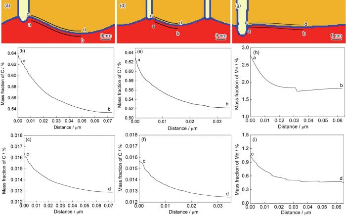
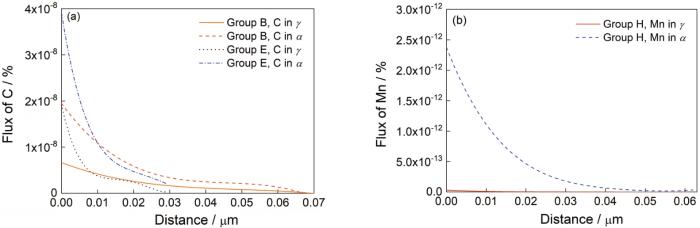
... 图11b展示了初始珠光体在720℃等温时,Mn在奥氏体和铁素体中的扩散通量.与740℃等温时C的扩散行为不同,Mn在两相中扩散通量相差了2个数量级,这是由于相较于C原子,Mn在铁素体中具有较高的溶解度,如初始珠光体组织中Mn在铁素体和渗碳体中的含量分别为1%和11%,其含量处于同一量级;不仅如此,由于铁素体具有较为松散的晶体结构,Mn在铁素体中的扩散系数远高于其在奥氏体中的扩散系数,因此造成了扩散通量的巨大差异,从而导致相比较于奥氏体扩散通道,Mn在铁素体中的扩散对相界面迁移速率的贡献更大.对比图9中720℃等温时考虑γ和γ + α扩散通道后相界面迁移速率的差异,发现对于PLE模式,Mn在奥氏体中的扩散对奥氏体/珠光体相界面迁移速率的贡献较小,主要依靠Mn在相界面和铁素体中的扩散,这与传统动力学分析中对PLE模式的认知[6,7,21]略有不同. ...
Effects of alloying elements on the kinetics of austenitization from pearlite in Fe-C-M alloys
6
2013
... 奥氏体化是钢铁材料热处理过程中至关重要的步骤,探究和阐明材料奥氏体化过程的相变机理,对钢铁材料的理论研究和工业生产意义重大[1].其中,珠光体-奥氏体相变涉及铁素体(α)、渗碳体(θ)和奥氏体(γ)三相耦合与合金元素在不同相之间的配分和扩散过程,是相变领域较为复杂的研究内容,其相变过程和物理本质上还存有很多待澄清的问题[2,3].在合金钢中,珠光体-奥氏体相变热动力学分析不仅取决于相变温度和合金成分,还受初始组织中渗碳体形貌[4,5]、合金元素分布[6,7]以及冷轧变形量[8,9]等诸多因素影响. ...
... 一般而言,珠光体-奥氏体相变由合金元素的扩散控制.Hillert等[10]阐述了以渗碳体+铁素体为初始组织的奥氏体相变过程,指出奥氏体和铁素体均可以成为合金元素的扩散通道(后文中称其为奥氏体扩散通道和铁素体扩散通道),相变热力学分析也因扩散通道的选择而有所不同.在较高的相变温度,奥氏体相变过程由间隙型合金元素C的扩散控制(non-partitioned local equilibrium,NPLE模式);在较低的相变温度,相变过程由置换型合金元素扩散进行控制(partitioned local equilibrium,PLE模式)[6,7].由于铁素体中合金原子的溶解度较低,目前的表征手段无法对其扩散通量进行精确测定,因此许多研究者忽略了铁素体中合金元素的扩散对奥氏体相变动力学的贡献[11~13].然而,与奥氏体相比,铁素体结构致密度较低,合金原子具有更大的扩散系数[14].是否可以忽略合金元素在铁素体中的扩散,成为研究奥氏体相变动力学的重要课题.对于球化珠光体的奥氏体化过程,一些研究者对铁素体扩散通道进行了探究和讨论.Akbay等[15]和Kapturkiewicz等[16]计算了C在铁素体中的扩散通量,认为引入铁素体扩散通道会减慢奥氏体相变动力学,但该研究未考虑远端渗碳体通过铁素体扩散对奥氏体生长过程的贡献,因此与真实物理过程差别较大.Miyamoto等[17]通过研究F-0.6C-M体系合金球化渗碳体+铁素体初始组织在1073 K等温时的奥氏体化过程,讨论了远端渗碳体通过铁素体扩散通道扩散对奥氏体生长过程的影响,认为C在铁素体中的扩散可以加快奥氏体/铁素体界面的迁移速率,证明了C通过铁素体扩散通道扩散对相变过程的影响是不可忽略的.Wu等[18]也建立了对于球化珠光体的奥氏体+铁素体双扩散通道模型,并将所计算的结果与原位中子衍射结果对比,认为远端渗碳体的快速溶解可以造成相变完成时奥氏体体积分数高于热力学平衡预测值. ...
... 然而,目前鲜有关于不同铁素体扩散通道对片层珠光体的奥氏体化过程贡献的报道,这是由于相较于球化珠光体,片层珠光体片层间距极小,且奥氏体长大速率较快,从而导致了通过传统实验手段无法测定铁素体中C浓度分布与奥氏体长大速率[19,20];不仅如此,对于奥氏体相变的PLE模式,目前也缺乏关于置换型合金原子扩散行为的系统研究,大多数研究者只考虑了其在奥氏体中的扩散[7,21,22].因此,计算模拟成为了研究扩散通道对珠光体-奥氏体相变动力学影响的有力手段.然而,Thermo-Calc和DICTRA等传统热、动力学模拟手段只能模拟一维相变过程[6,7,23],对于二维的片层珠光体-奥氏体相变,近年来发展较快的相场法(phase field method)则更适合模拟这一过程. ...
... ,7,23],对于二维的片层珠光体-奥氏体相变,近年来发展较快的相场法(phase field method)则更适合模拟这一过程. ...
... 图11b展示了初始珠光体在720℃等温时,Mn在奥氏体和铁素体中的扩散通量.与740℃等温时C的扩散行为不同,Mn在两相中扩散通量相差了2个数量级,这是由于相较于C原子,Mn在铁素体中具有较高的溶解度,如初始珠光体组织中Mn在铁素体和渗碳体中的含量分别为1%和11%,其含量处于同一量级;不仅如此,由于铁素体具有较为松散的晶体结构,Mn在铁素体中的扩散系数远高于其在奥氏体中的扩散系数,因此造成了扩散通量的巨大差异,从而导致相比较于奥氏体扩散通道,Mn在铁素体中的扩散对相界面迁移速率的贡献更大.对比图9中720℃等温时考虑γ和γ + α扩散通道后相界面迁移速率的差异,发现对于PLE模式,Mn在奥氏体中的扩散对奥氏体/珠光体相界面迁移速率的贡献较小,主要依靠Mn在相界面和铁素体中的扩散,这与传统动力学分析中对PLE模式的认知[6,7,21]略有不同. ...
... 然而,对于PLE模式相变,置换型合金原子主要通过界面等高通量扩散通道进行扩散,合金原子在界面中的扩散系数对动力学计算值影响极大.由图9可知,片层珠光体-奥氏体相变过程中,PLE与NPLE模式下界面迁移速率的差异远不及球化珠光体的奥氏体化[7,21~23],这是由于在类似本工作所示的相变过程中,Mn原子只发生了珠光体片层间距尺度的配分行为,并未发生长程扩散行为,而且该配分行为还通过大量的奥氏体/珠光体界面区域等高通量扩散通道进行,因此提高了PLE模式下的动力学过程.然而,对于球化珠光体的奥氏体化过程,理论上能够参与原子扩散的相界面面积十分有限,因此可以推测,铁素体扩散通道在此类过程中将发挥重要于奥氏体扩散通道的作用,即奥氏体在生长过程中将很大程度地受到邻近未相变渗碳体的影响,在对珠光体-奥氏体相变的PLE模式热动力学分析中,亦不能将铁素体扩散通道忽略. ...
Austenite formation in plain low-carbon steels
1
2011
... 奥氏体化是钢铁材料热处理过程中至关重要的步骤,探究和阐明材料奥氏体化过程的相变机理,对钢铁材料的理论研究和工业生产意义重大[1].其中,珠光体-奥氏体相变涉及铁素体(α)、渗碳体(θ)和奥氏体(γ)三相耦合与合金元素在不同相之间的配分和扩散过程,是相变领域较为复杂的研究内容,其相变过程和物理本质上还存有很多待澄清的问题[2,3].在合金钢中,珠光体-奥氏体相变热动力学分析不仅取决于相变温度和合金成分,还受初始组织中渗碳体形貌[4,5]、合金元素分布[6,7]以及冷轧变形量[8,9]等诸多因素影响. ...
Features of austenite formation in low-carbon steel during high speed heating induced by high-speed deformation
1
2020
... 奥氏体化是钢铁材料热处理过程中至关重要的步骤,探究和阐明材料奥氏体化过程的相变机理,对钢铁材料的理论研究和工业生产意义重大[1].其中,珠光体-奥氏体相变涉及铁素体(α)、渗碳体(θ)和奥氏体(γ)三相耦合与合金元素在不同相之间的配分和扩散过程,是相变领域较为复杂的研究内容,其相变过程和物理本质上还存有很多待澄清的问题[2,3].在合金钢中,珠光体-奥氏体相变热动力学分析不仅取决于相变温度和合金成分,还受初始组织中渗碳体形貌[4,5]、合金元素分布[6,7]以及冷轧变形量[8,9]等诸多因素影响. ...
Effect of alloying elements on the formation of austenite and dissolution of cementite
2
1971
... 一般而言,珠光体-奥氏体相变由合金元素的扩散控制.Hillert等[10]阐述了以渗碳体+铁素体为初始组织的奥氏体相变过程,指出奥氏体和铁素体均可以成为合金元素的扩散通道(后文中称其为奥氏体扩散通道和铁素体扩散通道),相变热力学分析也因扩散通道的选择而有所不同.在较高的相变温度,奥氏体相变过程由间隙型合金元素C的扩散控制(non-partitioned local equilibrium,NPLE模式);在较低的相变温度,相变过程由置换型合金元素扩散进行控制(partitioned local equilibrium,PLE模式)[6,7].由于铁素体中合金原子的溶解度较低,目前的表征手段无法对其扩散通量进行精确测定,因此许多研究者忽略了铁素体中合金元素的扩散对奥氏体相变动力学的贡献[11~13].然而,与奥氏体相比,铁素体结构致密度较低,合金原子具有更大的扩散系数[14].是否可以忽略合金元素在铁素体中的扩散,成为研究奥氏体相变动力学的重要课题.对于球化珠光体的奥氏体化过程,一些研究者对铁素体扩散通道进行了探究和讨论.Akbay等[15]和Kapturkiewicz等[16]计算了C在铁素体中的扩散通量,认为引入铁素体扩散通道会减慢奥氏体相变动力学,但该研究未考虑远端渗碳体通过铁素体扩散对奥氏体生长过程的贡献,因此与真实物理过程差别较大.Miyamoto等[17]通过研究F-0.6C-M体系合金球化渗碳体+铁素体初始组织在1073 K等温时的奥氏体化过程,讨论了远端渗碳体通过铁素体扩散通道扩散对奥氏体生长过程的影响,认为C在铁素体中的扩散可以加快奥氏体/铁素体界面的迁移速率,证明了C通过铁素体扩散通道扩散对相变过程的影响是不可忽略的.Wu等[18]也建立了对于球化珠光体的奥氏体+铁素体双扩散通道模型,并将所计算的结果与原位中子衍射结果对比,认为远端渗碳体的快速溶解可以造成相变完成时奥氏体体积分数高于热力学平衡预测值. ...
... 对于珠光体-奥氏体相变,界面迁移速率主要取决于合金原子在界面前沿的扩散通量.Hillert等[10]和Wu等[18]考虑了球化珠光体-奥氏体相变中远端渗碳体对奥氏体生长的影响,即远端渗碳体溶解在铁素体中,合金元素原子由渗碳体通过铁素体扩散至γ/α界面,从而加速γ/α界面的迁移.若相变过程由合金元素M的扩散控制,根据物质守恒原则,对于奥氏体/珠光体界面上任意一点,有: ...
Reaustenitisation in Fe-C steels revisited
1
1999
... 一般而言,珠光体-奥氏体相变由合金元素的扩散控制.Hillert等[10]阐述了以渗碳体+铁素体为初始组织的奥氏体相变过程,指出奥氏体和铁素体均可以成为合金元素的扩散通道(后文中称其为奥氏体扩散通道和铁素体扩散通道),相变热力学分析也因扩散通道的选择而有所不同.在较高的相变温度,奥氏体相变过程由间隙型合金元素C的扩散控制(non-partitioned local equilibrium,NPLE模式);在较低的相变温度,相变过程由置换型合金元素扩散进行控制(partitioned local equilibrium,PLE模式)[6,7].由于铁素体中合金原子的溶解度较低,目前的表征手段无法对其扩散通量进行精确测定,因此许多研究者忽略了铁素体中合金元素的扩散对奥氏体相变动力学的贡献[11~13].然而,与奥氏体相比,铁素体结构致密度较低,合金原子具有更大的扩散系数[14].是否可以忽略合金元素在铁素体中的扩散,成为研究奥氏体相变动力学的重要课题.对于球化珠光体的奥氏体化过程,一些研究者对铁素体扩散通道进行了探究和讨论.Akbay等[15]和Kapturkiewicz等[16]计算了C在铁素体中的扩散通量,认为引入铁素体扩散通道会减慢奥氏体相变动力学,但该研究未考虑远端渗碳体通过铁素体扩散对奥氏体生长过程的贡献,因此与真实物理过程差别较大.Miyamoto等[17]通过研究F-0.6C-M体系合金球化渗碳体+铁素体初始组织在1073 K等温时的奥氏体化过程,讨论了远端渗碳体通过铁素体扩散通道扩散对奥氏体生长过程的影响,认为C在铁素体中的扩散可以加快奥氏体/铁素体界面的迁移速率,证明了C通过铁素体扩散通道扩散对相变过程的影响是不可忽略的.Wu等[18]也建立了对于球化珠光体的奥氏体+铁素体双扩散通道模型,并将所计算的结果与原位中子衍射结果对比,认为远端渗碳体的快速溶解可以造成相变完成时奥氏体体积分数高于热力学平衡预测值. ...
Dilatometric analysis of cementite dissolution in hypereutectoid steels containing Cr
0
2011
Influence of morphology of cementite on kinetics of austenitization in the binary Fe-C system
1
2020
... 一般而言,珠光体-奥氏体相变由合金元素的扩散控制.Hillert等[10]阐述了以渗碳体+铁素体为初始组织的奥氏体相变过程,指出奥氏体和铁素体均可以成为合金元素的扩散通道(后文中称其为奥氏体扩散通道和铁素体扩散通道),相变热力学分析也因扩散通道的选择而有所不同.在较高的相变温度,奥氏体相变过程由间隙型合金元素C的扩散控制(non-partitioned local equilibrium,NPLE模式);在较低的相变温度,相变过程由置换型合金元素扩散进行控制(partitioned local equilibrium,PLE模式)[6,7].由于铁素体中合金原子的溶解度较低,目前的表征手段无法对其扩散通量进行精确测定,因此许多研究者忽略了铁素体中合金元素的扩散对奥氏体相变动力学的贡献[11~13].然而,与奥氏体相比,铁素体结构致密度较低,合金原子具有更大的扩散系数[14].是否可以忽略合金元素在铁素体中的扩散,成为研究奥氏体相变动力学的重要课题.对于球化珠光体的奥氏体化过程,一些研究者对铁素体扩散通道进行了探究和讨论.Akbay等[15]和Kapturkiewicz等[16]计算了C在铁素体中的扩散通量,认为引入铁素体扩散通道会减慢奥氏体相变动力学,但该研究未考虑远端渗碳体通过铁素体扩散对奥氏体生长过程的贡献,因此与真实物理过程差别较大.Miyamoto等[17]通过研究F-0.6C-M体系合金球化渗碳体+铁素体初始组织在1073 K等温时的奥氏体化过程,讨论了远端渗碳体通过铁素体扩散通道扩散对奥氏体生长过程的影响,认为C在铁素体中的扩散可以加快奥氏体/铁素体界面的迁移速率,证明了C通过铁素体扩散通道扩散对相变过程的影响是不可忽略的.Wu等[18]也建立了对于球化珠光体的奥氏体+铁素体双扩散通道模型,并将所计算的结果与原位中子衍射结果对比,认为远端渗碳体的快速溶解可以造成相变完成时奥氏体体积分数高于热力学平衡预测值. ...
Diffusion in iron
1
1969
... 一般而言,珠光体-奥氏体相变由合金元素的扩散控制.Hillert等[10]阐述了以渗碳体+铁素体为初始组织的奥氏体相变过程,指出奥氏体和铁素体均可以成为合金元素的扩散通道(后文中称其为奥氏体扩散通道和铁素体扩散通道),相变热力学分析也因扩散通道的选择而有所不同.在较高的相变温度,奥氏体相变过程由间隙型合金元素C的扩散控制(non-partitioned local equilibrium,NPLE模式);在较低的相变温度,相变过程由置换型合金元素扩散进行控制(partitioned local equilibrium,PLE模式)[6,7].由于铁素体中合金原子的溶解度较低,目前的表征手段无法对其扩散通量进行精确测定,因此许多研究者忽略了铁素体中合金元素的扩散对奥氏体相变动力学的贡献[11~13].然而,与奥氏体相比,铁素体结构致密度较低,合金原子具有更大的扩散系数[14].是否可以忽略合金元素在铁素体中的扩散,成为研究奥氏体相变动力学的重要课题.对于球化珠光体的奥氏体化过程,一些研究者对铁素体扩散通道进行了探究和讨论.Akbay等[15]和Kapturkiewicz等[16]计算了C在铁素体中的扩散通量,认为引入铁素体扩散通道会减慢奥氏体相变动力学,但该研究未考虑远端渗碳体通过铁素体扩散对奥氏体生长过程的贡献,因此与真实物理过程差别较大.Miyamoto等[17]通过研究F-0.6C-M体系合金球化渗碳体+铁素体初始组织在1073 K等温时的奥氏体化过程,讨论了远端渗碳体通过铁素体扩散通道扩散对奥氏体生长过程的影响,认为C在铁素体中的扩散可以加快奥氏体/铁素体界面的迁移速率,证明了C通过铁素体扩散通道扩散对相变过程的影响是不可忽略的.Wu等[18]也建立了对于球化珠光体的奥氏体+铁素体双扩散通道模型,并将所计算的结果与原位中子衍射结果对比,认为远端渗碳体的快速溶解可以造成相变完成时奥氏体体积分数高于热力学平衡预测值. ...
The influence of diffusion of carbon in ferrite as well as in austenite on a model of reaustenitization from ferrite/cementite mixtures in Fe-C steels
1
1996
... 一般而言,珠光体-奥氏体相变由合金元素的扩散控制.Hillert等[10]阐述了以渗碳体+铁素体为初始组织的奥氏体相变过程,指出奥氏体和铁素体均可以成为合金元素的扩散通道(后文中称其为奥氏体扩散通道和铁素体扩散通道),相变热力学分析也因扩散通道的选择而有所不同.在较高的相变温度,奥氏体相变过程由间隙型合金元素C的扩散控制(non-partitioned local equilibrium,NPLE模式);在较低的相变温度,相变过程由置换型合金元素扩散进行控制(partitioned local equilibrium,PLE模式)[6,7].由于铁素体中合金原子的溶解度较低,目前的表征手段无法对其扩散通量进行精确测定,因此许多研究者忽略了铁素体中合金元素的扩散对奥氏体相变动力学的贡献[11~13].然而,与奥氏体相比,铁素体结构致密度较低,合金原子具有更大的扩散系数[14].是否可以忽略合金元素在铁素体中的扩散,成为研究奥氏体相变动力学的重要课题.对于球化珠光体的奥氏体化过程,一些研究者对铁素体扩散通道进行了探究和讨论.Akbay等[15]和Kapturkiewicz等[16]计算了C在铁素体中的扩散通量,认为引入铁素体扩散通道会减慢奥氏体相变动力学,但该研究未考虑远端渗碳体通过铁素体扩散对奥氏体生长过程的贡献,因此与真实物理过程差别较大.Miyamoto等[17]通过研究F-0.6C-M体系合金球化渗碳体+铁素体初始组织在1073 K等温时的奥氏体化过程,讨论了远端渗碳体通过铁素体扩散通道扩散对奥氏体生长过程的影响,认为C在铁素体中的扩散可以加快奥氏体/铁素体界面的迁移速率,证明了C通过铁素体扩散通道扩散对相变过程的影响是不可忽略的.Wu等[18]也建立了对于球化珠光体的奥氏体+铁素体双扩散通道模型,并将所计算的结果与原位中子衍射结果对比,认为远端渗碳体的快速溶解可以造成相变完成时奥氏体体积分数高于热力学平衡预测值. ...
Computer simulation of the austenitizing process in cast iron with pearlitic matrix
1
2005
... 一般而言,珠光体-奥氏体相变由合金元素的扩散控制.Hillert等[10]阐述了以渗碳体+铁素体为初始组织的奥氏体相变过程,指出奥氏体和铁素体均可以成为合金元素的扩散通道(后文中称其为奥氏体扩散通道和铁素体扩散通道),相变热力学分析也因扩散通道的选择而有所不同.在较高的相变温度,奥氏体相变过程由间隙型合金元素C的扩散控制(non-partitioned local equilibrium,NPLE模式);在较低的相变温度,相变过程由置换型合金元素扩散进行控制(partitioned local equilibrium,PLE模式)[6,7].由于铁素体中合金原子的溶解度较低,目前的表征手段无法对其扩散通量进行精确测定,因此许多研究者忽略了铁素体中合金元素的扩散对奥氏体相变动力学的贡献[11~13].然而,与奥氏体相比,铁素体结构致密度较低,合金原子具有更大的扩散系数[14].是否可以忽略合金元素在铁素体中的扩散,成为研究奥氏体相变动力学的重要课题.对于球化珠光体的奥氏体化过程,一些研究者对铁素体扩散通道进行了探究和讨论.Akbay等[15]和Kapturkiewicz等[16]计算了C在铁素体中的扩散通量,认为引入铁素体扩散通道会减慢奥氏体相变动力学,但该研究未考虑远端渗碳体通过铁素体扩散对奥氏体生长过程的贡献,因此与真实物理过程差别较大.Miyamoto等[17]通过研究F-0.6C-M体系合金球化渗碳体+铁素体初始组织在1073 K等温时的奥氏体化过程,讨论了远端渗碳体通过铁素体扩散通道扩散对奥氏体生长过程的影响,认为C在铁素体中的扩散可以加快奥氏体/铁素体界面的迁移速率,证明了C通过铁素体扩散通道扩散对相变过程的影响是不可忽略的.Wu等[18]也建立了对于球化珠光体的奥氏体+铁素体双扩散通道模型,并将所计算的结果与原位中子衍射结果对比,认为远端渗碳体的快速溶解可以造成相变完成时奥氏体体积分数高于热力学平衡预测值. ...
Effects of Mn, Si and Cr addition on reverse transformation at 1073K from spheroidized cementite structure in Fe-0.6mass% C alloy
2
2010
... 一般而言,珠光体-奥氏体相变由合金元素的扩散控制.Hillert等[10]阐述了以渗碳体+铁素体为初始组织的奥氏体相变过程,指出奥氏体和铁素体均可以成为合金元素的扩散通道(后文中称其为奥氏体扩散通道和铁素体扩散通道),相变热力学分析也因扩散通道的选择而有所不同.在较高的相变温度,奥氏体相变过程由间隙型合金元素C的扩散控制(non-partitioned local equilibrium,NPLE模式);在较低的相变温度,相变过程由置换型合金元素扩散进行控制(partitioned local equilibrium,PLE模式)[6,7].由于铁素体中合金原子的溶解度较低,目前的表征手段无法对其扩散通量进行精确测定,因此许多研究者忽略了铁素体中合金元素的扩散对奥氏体相变动力学的贡献[11~13].然而,与奥氏体相比,铁素体结构致密度较低,合金原子具有更大的扩散系数[14].是否可以忽略合金元素在铁素体中的扩散,成为研究奥氏体相变动力学的重要课题.对于球化珠光体的奥氏体化过程,一些研究者对铁素体扩散通道进行了探究和讨论.Akbay等[15]和Kapturkiewicz等[16]计算了C在铁素体中的扩散通量,认为引入铁素体扩散通道会减慢奥氏体相变动力学,但该研究未考虑远端渗碳体通过铁素体扩散对奥氏体生长过程的贡献,因此与真实物理过程差别较大.Miyamoto等[17]通过研究F-0.6C-M体系合金球化渗碳体+铁素体初始组织在1073 K等温时的奥氏体化过程,讨论了远端渗碳体通过铁素体扩散通道扩散对奥氏体生长过程的影响,认为C在铁素体中的扩散可以加快奥氏体/铁素体界面的迁移速率,证明了C通过铁素体扩散通道扩散对相变过程的影响是不可忽略的.Wu等[18]也建立了对于球化珠光体的奥氏体+铁素体双扩散通道模型,并将所计算的结果与原位中子衍射结果对比,认为远端渗碳体的快速溶解可以造成相变完成时奥氏体体积分数高于热力学平衡预测值. ...
... 依据研究结果,对于NPLE相变模式,C扩散主要存在于奥氏体和铁素体中,相界面扩散通道的引入对相变动力学影响不大,这是由C原子的尺寸和扩散类型决定的.值得注意的是,C在铁素体中的扩散通量与其在奥氏体中扩散通量相当,若忽略铁素体扩散通道,可能会造成计算值与实验值在数值上的不同,但并不会造成相界面迁移速率量级上的差异.因此考虑铁素体扩散通道会使NPLE模式相变热动力学分析结果更加精确,从而可对早期研究中计算值与实验值产生的差异[17,18,35]进行解释. ...
Austenite formation kinetics from multicomponent cementite-ferrite aggregates
3
2020
... 一般而言,珠光体-奥氏体相变由合金元素的扩散控制.Hillert等[10]阐述了以渗碳体+铁素体为初始组织的奥氏体相变过程,指出奥氏体和铁素体均可以成为合金元素的扩散通道(后文中称其为奥氏体扩散通道和铁素体扩散通道),相变热力学分析也因扩散通道的选择而有所不同.在较高的相变温度,奥氏体相变过程由间隙型合金元素C的扩散控制(non-partitioned local equilibrium,NPLE模式);在较低的相变温度,相变过程由置换型合金元素扩散进行控制(partitioned local equilibrium,PLE模式)[6,7].由于铁素体中合金原子的溶解度较低,目前的表征手段无法对其扩散通量进行精确测定,因此许多研究者忽略了铁素体中合金元素的扩散对奥氏体相变动力学的贡献[11~13].然而,与奥氏体相比,铁素体结构致密度较低,合金原子具有更大的扩散系数[14].是否可以忽略合金元素在铁素体中的扩散,成为研究奥氏体相变动力学的重要课题.对于球化珠光体的奥氏体化过程,一些研究者对铁素体扩散通道进行了探究和讨论.Akbay等[15]和Kapturkiewicz等[16]计算了C在铁素体中的扩散通量,认为引入铁素体扩散通道会减慢奥氏体相变动力学,但该研究未考虑远端渗碳体通过铁素体扩散对奥氏体生长过程的贡献,因此与真实物理过程差别较大.Miyamoto等[17]通过研究F-0.6C-M体系合金球化渗碳体+铁素体初始组织在1073 K等温时的奥氏体化过程,讨论了远端渗碳体通过铁素体扩散通道扩散对奥氏体生长过程的影响,认为C在铁素体中的扩散可以加快奥氏体/铁素体界面的迁移速率,证明了C通过铁素体扩散通道扩散对相变过程的影响是不可忽略的.Wu等[18]也建立了对于球化珠光体的奥氏体+铁素体双扩散通道模型,并将所计算的结果与原位中子衍射结果对比,认为远端渗碳体的快速溶解可以造成相变完成时奥氏体体积分数高于热力学平衡预测值. ...
... 对于珠光体-奥氏体相变,界面迁移速率主要取决于合金原子在界面前沿的扩散通量.Hillert等[10]和Wu等[18]考虑了球化珠光体-奥氏体相变中远端渗碳体对奥氏体生长的影响,即远端渗碳体溶解在铁素体中,合金元素原子由渗碳体通过铁素体扩散至γ/α界面,从而加速γ/α界面的迁移.若相变过程由合金元素M的扩散控制,根据物质守恒原则,对于奥氏体/珠光体界面上任意一点,有: ...
... 依据研究结果,对于NPLE相变模式,C扩散主要存在于奥氏体和铁素体中,相界面扩散通道的引入对相变动力学影响不大,这是由C原子的尺寸和扩散类型决定的.值得注意的是,C在铁素体中的扩散通量与其在奥氏体中扩散通量相当,若忽略铁素体扩散通道,可能会造成计算值与实验值在数值上的不同,但并不会造成相界面迁移速率量级上的差异.因此考虑铁素体扩散通道会使NPLE模式相变热动力学分析结果更加精确,从而可对早期研究中计算值与实验值产生的差异[17,18,35]进行解释. ...
Phase transformation and microstructure evolution of pearlite heat-resistant steel during heating
1
2020
... 然而,目前鲜有关于不同铁素体扩散通道对片层珠光体的奥氏体化过程贡献的报道,这是由于相较于球化珠光体,片层珠光体片层间距极小,且奥氏体长大速率较快,从而导致了通过传统实验手段无法测定铁素体中C浓度分布与奥氏体长大速率[19,20];不仅如此,对于奥氏体相变的PLE模式,目前也缺乏关于置换型合金原子扩散行为的系统研究,大多数研究者只考虑了其在奥氏体中的扩散[7,21,22].因此,计算模拟成为了研究扩散通道对珠光体-奥氏体相变动力学影响的有力手段.然而,Thermo-Calc和DICTRA等传统热、动力学模拟手段只能模拟一维相变过程[6,7,23],对于二维的片层珠光体-奥氏体相变,近年来发展较快的相场法(phase field method)则更适合模拟这一过程. ...
Direct observation of austenite and pearlite formation in thermally simulated coarse grain heat-affected zone of pearlite railway steel
2
2021
... 然而,目前鲜有关于不同铁素体扩散通道对片层珠光体的奥氏体化过程贡献的报道,这是由于相较于球化珠光体,片层珠光体片层间距极小,且奥氏体长大速率较快,从而导致了通过传统实验手段无法测定铁素体中C浓度分布与奥氏体长大速率[19,20];不仅如此,对于奥氏体相变的PLE模式,目前也缺乏关于置换型合金原子扩散行为的系统研究,大多数研究者只考虑了其在奥氏体中的扩散[7,21,22].因此,计算模拟成为了研究扩散通道对珠光体-奥氏体相变动力学影响的有力手段.然而,Thermo-Calc和DICTRA等传统热、动力学模拟手段只能模拟一维相变过程[6,7,23],对于二维的片层珠光体-奥氏体相变,近年来发展较快的相场法(phase field method)则更适合模拟这一过程. ...
... 奥氏体/珠光体界面迁移速率是微观动力学参量,由于珠光体组织复杂、片层间距小,且奥氏体生长速率较快,目前常用的实验手段还无法精确地测定奥氏体/珠光体界面迁移速率.对于奥氏体相变而言,其原位观察结果与珠光体相变、铁素体相变等降温相变过程有所差别:奥氏体晶界逐渐在组织中显露出来,因此研究者无法从原位直接观察奥氏体/珠光体界面的迁移情况[20],只能用相场法估算奥氏体/珠光体界面迁移速率.为了简化物理过程,作如下合理假设:(1) 假设奥氏体在初始组织中为爆发性形核,相当于忽略在生长过程中奥氏体形核对动力学曲线的影响[21];(2) 在奥氏体生长过程中,合金原子扩散仅发生于渗碳体片层与铁素体片层之间[37,38],相当于不存在奥氏体晶粒间产生的浓度场软碰撞,因此认为奥氏体/珠光体界面迁移速率在发生晶粒间硬碰撞前为恒定值.基于如上假设,本工作利用Avrami-Johnson-Mehl (JMA)方程拟合动力学数据,并从中粗略估算出奥氏体相长大速率[39]. ...
Kinetics of reverse transformation from pearlite to austenite in an Fe-0.6 mass pct C alloy and the effects of alloying elements
4
2011
... 然而,目前鲜有关于不同铁素体扩散通道对片层珠光体的奥氏体化过程贡献的报道,这是由于相较于球化珠光体,片层珠光体片层间距极小,且奥氏体长大速率较快,从而导致了通过传统实验手段无法测定铁素体中C浓度分布与奥氏体长大速率[19,20];不仅如此,对于奥氏体相变的PLE模式,目前也缺乏关于置换型合金原子扩散行为的系统研究,大多数研究者只考虑了其在奥氏体中的扩散[7,21,22].因此,计算模拟成为了研究扩散通道对珠光体-奥氏体相变动力学影响的有力手段.然而,Thermo-Calc和DICTRA等传统热、动力学模拟手段只能模拟一维相变过程[6,7,23],对于二维的片层珠光体-奥氏体相变,近年来发展较快的相场法(phase field method)则更适合模拟这一过程. ...
... 奥氏体/珠光体界面迁移速率是微观动力学参量,由于珠光体组织复杂、片层间距小,且奥氏体生长速率较快,目前常用的实验手段还无法精确地测定奥氏体/珠光体界面迁移速率.对于奥氏体相变而言,其原位观察结果与珠光体相变、铁素体相变等降温相变过程有所差别:奥氏体晶界逐渐在组织中显露出来,因此研究者无法从原位直接观察奥氏体/珠光体界面的迁移情况[20],只能用相场法估算奥氏体/珠光体界面迁移速率.为了简化物理过程,作如下合理假设:(1) 假设奥氏体在初始组织中为爆发性形核,相当于忽略在生长过程中奥氏体形核对动力学曲线的影响[21];(2) 在奥氏体生长过程中,合金原子扩散仅发生于渗碳体片层与铁素体片层之间[37,38],相当于不存在奥氏体晶粒间产生的浓度场软碰撞,因此认为奥氏体/珠光体界面迁移速率在发生晶粒间硬碰撞前为恒定值.基于如上假设,本工作利用Avrami-Johnson-Mehl (JMA)方程拟合动力学数据,并从中粗略估算出奥氏体相长大速率[39]. ...
... 图11b展示了初始珠光体在720℃等温时,Mn在奥氏体和铁素体中的扩散通量.与740℃等温时C的扩散行为不同,Mn在两相中扩散通量相差了2个数量级,这是由于相较于C原子,Mn在铁素体中具有较高的溶解度,如初始珠光体组织中Mn在铁素体和渗碳体中的含量分别为1%和11%,其含量处于同一量级;不仅如此,由于铁素体具有较为松散的晶体结构,Mn在铁素体中的扩散系数远高于其在奥氏体中的扩散系数,因此造成了扩散通量的巨大差异,从而导致相比较于奥氏体扩散通道,Mn在铁素体中的扩散对相界面迁移速率的贡献更大.对比图9中720℃等温时考虑γ和γ + α扩散通道后相界面迁移速率的差异,发现对于PLE模式,Mn在奥氏体中的扩散对奥氏体/珠光体相界面迁移速率的贡献较小,主要依靠Mn在相界面和铁素体中的扩散,这与传统动力学分析中对PLE模式的认知[6,7,21]略有不同. ...
... 然而,对于PLE模式相变,置换型合金原子主要通过界面等高通量扩散通道进行扩散,合金原子在界面中的扩散系数对动力学计算值影响极大.由图9可知,片层珠光体-奥氏体相变过程中,PLE与NPLE模式下界面迁移速率的差异远不及球化珠光体的奥氏体化[7,21~23],这是由于在类似本工作所示的相变过程中,Mn原子只发生了珠光体片层间距尺度的配分行为,并未发生长程扩散行为,而且该配分行为还通过大量的奥氏体/珠光体界面区域等高通量扩散通道进行,因此提高了PLE模式下的动力学过程.然而,对于球化珠光体的奥氏体化过程,理论上能够参与原子扩散的相界面面积十分有限,因此可以推测,铁素体扩散通道在此类过程中将发挥重要于奥氏体扩散通道的作用,即奥氏体在生长过程中将很大程度地受到邻近未相变渗碳体的影响,在对珠光体-奥氏体相变的PLE模式热动力学分析中,亦不能将铁素体扩散通道忽略. ...
Effect of alloying element partition in pearlite on the growth of austenite in high-carbon low alloy steel
1
2016
... 然而,目前鲜有关于不同铁素体扩散通道对片层珠光体的奥氏体化过程贡献的报道,这是由于相较于球化珠光体,片层珠光体片层间距极小,且奥氏体长大速率较快,从而导致了通过传统实验手段无法测定铁素体中C浓度分布与奥氏体长大速率[19,20];不仅如此,对于奥氏体相变的PLE模式,目前也缺乏关于置换型合金原子扩散行为的系统研究,大多数研究者只考虑了其在奥氏体中的扩散[7,21,22].因此,计算模拟成为了研究扩散通道对珠光体-奥氏体相变动力学影响的有力手段.然而,Thermo-Calc和DICTRA等传统热、动力学模拟手段只能模拟一维相变过程[6,7,23],对于二维的片层珠光体-奥氏体相变,近年来发展较快的相场法(phase field method)则更适合模拟这一过程. ...
Transition between alloy-element partitioned and non-partitioned growth of austenite from a ferrite and cementite mixture in a high-carbon low-alloy steel
2
2016
... 然而,目前鲜有关于不同铁素体扩散通道对片层珠光体的奥氏体化过程贡献的报道,这是由于相较于球化珠光体,片层珠光体片层间距极小,且奥氏体长大速率较快,从而导致了通过传统实验手段无法测定铁素体中C浓度分布与奥氏体长大速率[19,20];不仅如此,对于奥氏体相变的PLE模式,目前也缺乏关于置换型合金原子扩散行为的系统研究,大多数研究者只考虑了其在奥氏体中的扩散[7,21,22].因此,计算模拟成为了研究扩散通道对珠光体-奥氏体相变动力学影响的有力手段.然而,Thermo-Calc和DICTRA等传统热、动力学模拟手段只能模拟一维相变过程[6,7,23],对于二维的片层珠光体-奥氏体相变,近年来发展较快的相场法(phase field method)则更适合模拟这一过程. ...
... 然而,对于PLE模式相变,置换型合金原子主要通过界面等高通量扩散通道进行扩散,合金原子在界面中的扩散系数对动力学计算值影响极大.由图9可知,片层珠光体-奥氏体相变过程中,PLE与NPLE模式下界面迁移速率的差异远不及球化珠光体的奥氏体化[7,21~23],这是由于在类似本工作所示的相变过程中,Mn原子只发生了珠光体片层间距尺度的配分行为,并未发生长程扩散行为,而且该配分行为还通过大量的奥氏体/珠光体界面区域等高通量扩散通道进行,因此提高了PLE模式下的动力学过程.然而,对于球化珠光体的奥氏体化过程,理论上能够参与原子扩散的相界面面积十分有限,因此可以推测,铁素体扩散通道在此类过程中将发挥重要于奥氏体扩散通道的作用,即奥氏体在生长过程中将很大程度地受到邻近未相变渗碳体的影响,在对珠光体-奥氏体相变的PLE模式热动力学分析中,亦不能将铁素体扩散通道忽略. ...
Phase-field models for microstructure evolution
2
2002
... 相场法是一种基于Ginzburg-Landau自由能泛函理论构建的模拟手段,主要用于模拟介观尺度下组织随时间演化的过程,并预测复杂形貌演化[24].相较于传统尖锐界面模型,相场法利用弥散界面模型,即界面处与基体在数值计算上保持连续,是一种强有力的描述固态相变过程的模拟工具[25],已经广泛应用在珠光体相变[26,27]、铁素体相变[28,29]等领域.Militzer和Azizi-Alizamini[30]利用MICRESS软件[31]模拟了Fe-C二元合金体中,全珠光体和珠光体+铁素体为初始组织的奥氏体相变组织演化过程;Rudnizki等[32]利用基于NPLE模型的相场模型模拟了冷轧双相钢的奥氏体化过程,其结果与实验结果吻合较好;Zhang等[33]在相场模型中同时考虑了扩散控制机制与界面控制机制,研究了Fe-9.6Ni-7.1Mn马氏体钢的奥氏体相变过程,讨论了奥氏体的形核及长大过程. ...
... 相场模型根据体系整体Gibbs自由能降低的原则对组织演化进行模拟和预测[24,25].结合热力学原理,可推导出双壁垒势条件下的相场方程[26]: ...
Phase field modeling of microstructure evolution in steels
2
2011
... 相场法是一种基于Ginzburg-Landau自由能泛函理论构建的模拟手段,主要用于模拟介观尺度下组织随时间演化的过程,并预测复杂形貌演化[24].相较于传统尖锐界面模型,相场法利用弥散界面模型,即界面处与基体在数值计算上保持连续,是一种强有力的描述固态相变过程的模拟工具[25],已经广泛应用在珠光体相变[26,27]、铁素体相变[28,29]等领域.Militzer和Azizi-Alizamini[30]利用MICRESS软件[31]模拟了Fe-C二元合金体中,全珠光体和珠光体+铁素体为初始组织的奥氏体相变组织演化过程;Rudnizki等[32]利用基于NPLE模型的相场模型模拟了冷轧双相钢的奥氏体化过程,其结果与实验结果吻合较好;Zhang等[33]在相场模型中同时考虑了扩散控制机制与界面控制机制,研究了Fe-9.6Ni-7.1Mn马氏体钢的奥氏体相变过程,讨论了奥氏体的形核及长大过程. ...
... 相场模型根据体系整体Gibbs自由能降低的原则对组织演化进行模拟和预测[24,25].结合热力学原理,可推导出双壁垒势条件下的相场方程[26]: ...
The role of carbon diffusion in ferrite on the kinetics of cooperative growth of pearlite: A multi-phase field study
6
2006
... 相场法是一种基于Ginzburg-Landau自由能泛函理论构建的模拟手段,主要用于模拟介观尺度下组织随时间演化的过程,并预测复杂形貌演化[24].相较于传统尖锐界面模型,相场法利用弥散界面模型,即界面处与基体在数值计算上保持连续,是一种强有力的描述固态相变过程的模拟工具[25],已经广泛应用在珠光体相变[26,27]、铁素体相变[28,29]等领域.Militzer和Azizi-Alizamini[30]利用MICRESS软件[31]模拟了Fe-C二元合金体中,全珠光体和珠光体+铁素体为初始组织的奥氏体相变组织演化过程;Rudnizki等[32]利用基于NPLE模型的相场模型模拟了冷轧双相钢的奥氏体化过程,其结果与实验结果吻合较好;Zhang等[33]在相场模型中同时考虑了扩散控制机制与界面控制机制,研究了Fe-9.6Ni-7.1Mn马氏体钢的奥氏体相变过程,讨论了奥氏体的形核及长大过程. ...
... 相场模型根据体系整体Gibbs自由能降低的原则对组织演化进行模拟和预测[24,25].结合热力学原理,可推导出双壁垒势条件下的相场方程[26]: ...
... 式中,t为时间,μij 为界面迁移率,σij 为界面能,η为界面厚度,ΔGij 为两相自由能差值.在模拟过程中,假设所有相均为各向同性,因此对于i/j相界面,迁移率和界面能处处相等.该方程的前一部分代表了界面的曲率,后一部分代表了热力学驱动力.其中热力学驱动力ΔGij 的计算方法为[26]: ...
... 不同条件的参数和所对应的编号如表1所示,计算过程中所涉及的其他参数如表2[26,36]所示,热力学和动力学数据分别由TCFE7和MOB2数据库调取. ...
... 本模拟涉及物理量及其取值[26,36] ...
... Materials data used in the phase-field calculations[26,36] ...
The influence of lattice strain on pearlite formation in Fe-C
1
2007
... 相场法是一种基于Ginzburg-Landau自由能泛函理论构建的模拟手段,主要用于模拟介观尺度下组织随时间演化的过程,并预测复杂形貌演化[24].相较于传统尖锐界面模型,相场法利用弥散界面模型,即界面处与基体在数值计算上保持连续,是一种强有力的描述固态相变过程的模拟工具[25],已经广泛应用在珠光体相变[26,27]、铁素体相变[28,29]等领域.Militzer和Azizi-Alizamini[30]利用MICRESS软件[31]模拟了Fe-C二元合金体中,全珠光体和珠光体+铁素体为初始组织的奥氏体相变组织演化过程;Rudnizki等[32]利用基于NPLE模型的相场模型模拟了冷轧双相钢的奥氏体化过程,其结果与实验结果吻合较好;Zhang等[33]在相场模型中同时考虑了扩散控制机制与界面控制机制,研究了Fe-9.6Ni-7.1Mn马氏体钢的奥氏体相变过程,讨论了奥氏体的形核及长大过程. ...
The phase-field approach and solute drag modeling of the transition to massive γ→α transformation in binary Fe-C alloys
1
2003
... 相场法是一种基于Ginzburg-Landau自由能泛函理论构建的模拟手段,主要用于模拟介观尺度下组织随时间演化的过程,并预测复杂形貌演化[24].相较于传统尖锐界面模型,相场法利用弥散界面模型,即界面处与基体在数值计算上保持连续,是一种强有力的描述固态相变过程的模拟工具[25],已经广泛应用在珠光体相变[26,27]、铁素体相变[28,29]等领域.Militzer和Azizi-Alizamini[30]利用MICRESS软件[31]模拟了Fe-C二元合金体中,全珠光体和珠光体+铁素体为初始组织的奥氏体相变组织演化过程;Rudnizki等[32]利用基于NPLE模型的相场模型模拟了冷轧双相钢的奥氏体化过程,其结果与实验结果吻合较好;Zhang等[33]在相场模型中同时考虑了扩散控制机制与界面控制机制,研究了Fe-9.6Ni-7.1Mn马氏体钢的奥氏体相变过程,讨论了奥氏体的形核及长大过程. ...
A phase-field simulation of austenite to ferrite transformation kinetics in low carbon steels
1
2006
... 相场法是一种基于Ginzburg-Landau自由能泛函理论构建的模拟手段,主要用于模拟介观尺度下组织随时间演化的过程,并预测复杂形貌演化[24].相较于传统尖锐界面模型,相场法利用弥散界面模型,即界面处与基体在数值计算上保持连续,是一种强有力的描述固态相变过程的模拟工具[25],已经广泛应用在珠光体相变[26,27]、铁素体相变[28,29]等领域.Militzer和Azizi-Alizamini[30]利用MICRESS软件[31]模拟了Fe-C二元合金体中,全珠光体和珠光体+铁素体为初始组织的奥氏体相变组织演化过程;Rudnizki等[32]利用基于NPLE模型的相场模型模拟了冷轧双相钢的奥氏体化过程,其结果与实验结果吻合较好;Zhang等[33]在相场模型中同时考虑了扩散控制机制与界面控制机制,研究了Fe-9.6Ni-7.1Mn马氏体钢的奥氏体相变过程,讨论了奥氏体的形核及长大过程. ...
Phase field modelling of austenite formation in low carbon steels
1
2011
... 相场法是一种基于Ginzburg-Landau自由能泛函理论构建的模拟手段,主要用于模拟介观尺度下组织随时间演化的过程,并预测复杂形貌演化[24].相较于传统尖锐界面模型,相场法利用弥散界面模型,即界面处与基体在数值计算上保持连续,是一种强有力的描述固态相变过程的模拟工具[25],已经广泛应用在珠光体相变[26,27]、铁素体相变[28,29]等领域.Militzer和Azizi-Alizamini[30]利用MICRESS软件[31]模拟了Fe-C二元合金体中,全珠光体和珠光体+铁素体为初始组织的奥氏体相变组织演化过程;Rudnizki等[32]利用基于NPLE模型的相场模型模拟了冷轧双相钢的奥氏体化过程,其结果与实验结果吻合较好;Zhang等[33]在相场模型中同时考虑了扩散控制机制与界面控制机制,研究了Fe-9.6Ni-7.1Mn马氏体钢的奥氏体相变过程,讨论了奥氏体的形核及长大过程. ...
1
... 相场法是一种基于Ginzburg-Landau自由能泛函理论构建的模拟手段,主要用于模拟介观尺度下组织随时间演化的过程,并预测复杂形貌演化[24].相较于传统尖锐界面模型,相场法利用弥散界面模型,即界面处与基体在数值计算上保持连续,是一种强有力的描述固态相变过程的模拟工具[25],已经广泛应用在珠光体相变[26,27]、铁素体相变[28,29]等领域.Militzer和Azizi-Alizamini[30]利用MICRESS软件[31]模拟了Fe-C二元合金体中,全珠光体和珠光体+铁素体为初始组织的奥氏体相变组织演化过程;Rudnizki等[32]利用基于NPLE模型的相场模型模拟了冷轧双相钢的奥氏体化过程,其结果与实验结果吻合较好;Zhang等[33]在相场模型中同时考虑了扩散控制机制与界面控制机制,研究了Fe-9.6Ni-7.1Mn马氏体钢的奥氏体相变过程,讨论了奥氏体的形核及长大过程. ...
Phase-field modeling of austenite formation from a ferrite plus pearlite microstructure during annealing of cold-rolled dual-phase steel
1
2011
... 相场法是一种基于Ginzburg-Landau自由能泛函理论构建的模拟手段,主要用于模拟介观尺度下组织随时间演化的过程,并预测复杂形貌演化[24].相较于传统尖锐界面模型,相场法利用弥散界面模型,即界面处与基体在数值计算上保持连续,是一种强有力的描述固态相变过程的模拟工具[25],已经广泛应用在珠光体相变[26,27]、铁素体相变[28,29]等领域.Militzer和Azizi-Alizamini[30]利用MICRESS软件[31]模拟了Fe-C二元合金体中,全珠光体和珠光体+铁素体为初始组织的奥氏体相变组织演化过程;Rudnizki等[32]利用基于NPLE模型的相场模型模拟了冷轧双相钢的奥氏体化过程,其结果与实验结果吻合较好;Zhang等[33]在相场模型中同时考虑了扩散控制机制与界面控制机制,研究了Fe-9.6Ni-7.1Mn马氏体钢的奥氏体相变过程,讨论了奥氏体的形核及长大过程. ...
Phase-field simulation of austenite reversion in a Fe-9.6Ni-7.1Mn (at.%) martensitic steel governed by a coupled diffusional/displacive mechanism
1
2020
... 相场法是一种基于Ginzburg-Landau自由能泛函理论构建的模拟手段,主要用于模拟介观尺度下组织随时间演化的过程,并预测复杂形貌演化[24].相较于传统尖锐界面模型,相场法利用弥散界面模型,即界面处与基体在数值计算上保持连续,是一种强有力的描述固态相变过程的模拟工具[25],已经广泛应用在珠光体相变[26,27]、铁素体相变[28,29]等领域.Militzer和Azizi-Alizamini[30]利用MICRESS软件[31]模拟了Fe-C二元合金体中,全珠光体和珠光体+铁素体为初始组织的奥氏体相变组织演化过程;Rudnizki等[32]利用基于NPLE模型的相场模型模拟了冷轧双相钢的奥氏体化过程,其结果与实验结果吻合较好;Zhang等[33]在相场模型中同时考虑了扩散控制机制与界面控制机制,研究了Fe-9.6Ni-7.1Mn马氏体钢的奥氏体相变过程,讨论了奥氏体的形核及长大过程. ...
The multiphase-field model with an integrated concept for modelling solute diffusion
1
1998
... 式中,ΔSij 为转变熵,T为相变温度,T r为参考温度,mij 为相图中给定点的切线斜率,ci 和分别为第i相的浓度及其在参考温度下的浓度.在除界面外的区域,单溶质扩散的计算满足标准Fick扩散方程[34]: ...
Study of partition to non-partition transition of austenite growth along pearlite lamellae in near-eutectoid Fe-C-Mn alloy
7
2019
... 本工作研究Fe-C-Mn合金体系在720和740℃等温时的奥氏体相变过程,实验材料合金成分(质量分数,%,下同)为:C 0.62,Mn 2.30,P < 0.009,S < 0.004,Fe余量,相变平衡温度Ae1为684℃,Ae3为716℃.合金初始组织为等温处理后的全片层珠光体组织,片层间距为150~200 nm,其中Mn在渗碳体和铁素体中的含量(质量分数)分别为11%和1%,初始组织制备和部分实验结果见文献[35]. ...
... 对于相场模拟部分,选取Fe-0.6%C-2%Mn合金体系,初始珠光体组织中铁素体与渗碳体的体积分数和C含量由Thermo-Calc计算平衡状态得出;Mn含量分别设置为1%和11%,与实验结果相对应[35];渗碳体中Fe原子与C原子满足化学计量比,故其中不存在C扩散.在珠光体-奥氏体相变中存在置换型合金元素配分与不配分转变温度(partitioned and non-partitioned transition temperature,PNTT),该特征温度由Mn在初始珠光体中的配分程度决定[6],对于本工作的初始组织,实验测定的PNTT处于720~725℃[35],因此720和740℃分别位于PNTT温度两侧.在等温温度为740℃时,将相变模式设定为NPLE模式,为讨论初始珠光体组织片层间距对奥氏体相变的影响,设置珠光体片层间距为150与75 nm;在等温温度为720℃时,将相变模式设定为PLE模式,珠光体片层间距为150 nm.假设奥氏体在珠光体团边界形核,并沿α/θ界面方向长大,由于本工作侧重于奥氏体的长大过程,对形核过程不予考虑,因此预先在初始组织底部添加一定厚度的奥氏体薄膜,使其成分与合金成分相同,观察奥氏体/珠光体界面迁移情况. ...
... [35],因此720和740℃分别位于PNTT温度两侧.在等温温度为740℃时,将相变模式设定为NPLE模式,为讨论初始珠光体组织片层间距对奥氏体相变的影响,设置珠光体片层间距为150与75 nm;在等温温度为720℃时,将相变模式设定为PLE模式,珠光体片层间距为150 nm.假设奥氏体在珠光体团边界形核,并沿α/θ界面方向长大,由于本工作侧重于奥氏体的长大过程,对形核过程不予考虑,因此预先在初始组织底部添加一定厚度的奥氏体薄膜,使其成分与合金成分相同,观察奥氏体/珠光体界面迁移情况. ...
... 图3展示了初始珠光体在720℃等温60 s后的组织形貌以及Mn在新生奥氏体中的分布.根据图2所示动力学曲线,此时奥氏体相变还未完成.选取图3a中珠光体/奥氏体相界面附近的组织在TEM下观察,并测定垂直界面与沿界面方向的Mn浓度的分布情况,如图3b中A、B线所示,Mn浓度分布如图3c和d中所示,其中图3c中出现的Mn浓度尖锋代表了未发生转变的渗碳体颗粒中的Mn含量,而在新生奥氏体中没有明显的Mn的不均匀分布.这一结果说明初始珠光体组织在该温度下保温时,Mn在相变过程中发生了配分与长程扩散,结合PNTT理论[35],可证明720℃等温时相变模式为PLE模式,相界面迁移由Mn扩散控制. ...
... 图4a展示了初始珠光体在740℃等温20 s后的组织形貌.可以看到,马氏体基体中存在大量的膜状残余奥氏体,即“伪珠光体”组织(ghost pearlite)[36,43],这是由于相变过程中Mn没有发生配分,从而在原渗碳体和原铁素体位置分别形成富Mn区和贫Mn区,进而产生淬透性差异,最终形成该类膜状残余奥氏体组织[35].图4b和c所示为利用STEM-EDS测定该区域Mn的浓度,能够观察到明显的Mn的不均匀分布,证明该温度下相变模式为NPLE模式,相界面迁移由C扩散控制. ...
... 相场法可以模拟复杂的组织演化,图5所示为初始组织在740℃等温时(表1中A、D组)的形貌演化过程.可以看到,相变过程中奥氏体/珠光体相界面并不平直,且渗碳体在新生奥氏体中的溶解滞后于相界面的迁移,这与实验观察到的结果[35]一致.对于小片层间距(75 nm)的初始珠光体组织,可以看到奥氏体/珠光体界面弯曲程度较小,且相界面迁移速率较快. ...
... 依据研究结果,对于NPLE相变模式,C扩散主要存在于奥氏体和铁素体中,相界面扩散通道的引入对相变动力学影响不大,这是由C原子的尺寸和扩散类型决定的.值得注意的是,C在铁素体中的扩散通量与其在奥氏体中扩散通量相当,若忽略铁素体扩散通道,可能会造成计算值与实验值在数值上的不同,但并不会造成相界面迁移速率量级上的差异.因此考虑铁素体扩散通道会使NPLE模式相变热动力学分析结果更加精确,从而可对早期研究中计算值与实验值产生的差异[17,18,35]进行解释. ...
Effects of alloying element partition and its interfacial segregation on the thermodynamics and kinetics of phase transformation in steels
6
2017
... 对于不同等温温度和珠光体片层间距,分别设置γ、γ + α和γ + α + interface 3种扩散通道组合,其中interface代表允许合金元素在奥氏体/珠光体界面进行扩散,实现此过程的处理手段为在界面附近的奥氏体相内附加厚度为0.5 nm的高通量扩散通道,通过在体扩散的激活能基础上减去一定的能量差值定义相界面扩散激活能[36]. ...
... 不同条件的参数和所对应的编号如表1所示,计算过程中所涉及的其他参数如表2[26,36]所示,热力学和动力学数据分别由TCFE7和MOB2数据库调取. ...
... 本模拟涉及物理量及其取值[26,36] ...
... Materials data used in the phase-field calculations[26,36] ...
... 图4a展示了初始珠光体在740℃等温20 s后的组织形貌.可以看到,马氏体基体中存在大量的膜状残余奥氏体,即“伪珠光体”组织(ghost pearlite)[36,43],这是由于相变过程中Mn没有发生配分,从而在原渗碳体和原铁素体位置分别形成富Mn区和贫Mn区,进而产生淬透性差异,最终形成该类膜状残余奥氏体组织[35].图4b和c所示为利用STEM-EDS测定该区域Mn的浓度,能够观察到明显的Mn的不均匀分布,证明该温度下相变模式为NPLE模式,相界面迁移由C扩散控制. ...
... 图12所示为奥氏体/珠光体界面迁移速率随激活能的变化趋势,假设不发生变化,相场计算过程中所用到的界面扩散激活能如圆点所示(155 kJ/mol),实验估测值所对应的界面扩散激活能如菱形点所示(118 kJ/mol),可以看到对于相界面扩散激活能的选取可以很大程度上改变扩散系数的大小.而本工作选取的C、Mn扩散激活能为文献[36]中所报道的数值,其准确性和可靠性远低于热力学数据库,因此实验估测值与计算值的误差主要来源于实验方法本征的误差和计算过程中对界面扩散激活能的选取.不仅如此,此结果也忽略了界面迁移率对界面迁移速率的影响.但可以肯定的是,真实相变过程中的相界面迁移速率要远高于不引入相界面扩散通道的模拟组别(表1中H、I组),因此可以证明对于片层珠光体-奥氏体相变的PLE模式而言,Mn在相界面中的扩散对相变动力学起到了主要作用. ...
合金元素配分与偏聚对钢中相变热力学及动力学的影响
6
2017
... 对于不同等温温度和珠光体片层间距,分别设置γ、γ + α和γ + α + interface 3种扩散通道组合,其中interface代表允许合金元素在奥氏体/珠光体界面进行扩散,实现此过程的处理手段为在界面附近的奥氏体相内附加厚度为0.5 nm的高通量扩散通道,通过在体扩散的激活能基础上减去一定的能量差值定义相界面扩散激活能[36]. ...
... 不同条件的参数和所对应的编号如表1所示,计算过程中所涉及的其他参数如表2[26,36]所示,热力学和动力学数据分别由TCFE7和MOB2数据库调取. ...
... 本模拟涉及物理量及其取值[26,36] ...
... Materials data used in the phase-field calculations[26,36] ...
... 图4a展示了初始珠光体在740℃等温20 s后的组织形貌.可以看到,马氏体基体中存在大量的膜状残余奥氏体,即“伪珠光体”组织(ghost pearlite)[36,43],这是由于相变过程中Mn没有发生配分,从而在原渗碳体和原铁素体位置分别形成富Mn区和贫Mn区,进而产生淬透性差异,最终形成该类膜状残余奥氏体组织[35].图4b和c所示为利用STEM-EDS测定该区域Mn的浓度,能够观察到明显的Mn的不均匀分布,证明该温度下相变模式为NPLE模式,相界面迁移由C扩散控制. ...
... 图12所示为奥氏体/珠光体界面迁移速率随激活能的变化趋势,假设不发生变化,相场计算过程中所用到的界面扩散激活能如圆点所示(155 kJ/mol),实验估测值所对应的界面扩散激活能如菱形点所示(118 kJ/mol),可以看到对于相界面扩散激活能的选取可以很大程度上改变扩散系数的大小.而本工作选取的C、Mn扩散激活能为文献[36]中所报道的数值,其准确性和可靠性远低于热力学数据库,因此实验估测值与计算值的误差主要来源于实验方法本征的误差和计算过程中对界面扩散激活能的选取.不仅如此,此结果也忽略了界面迁移率对界面迁移速率的影响.但可以肯定的是,真实相变过程中的相界面迁移速率要远高于不引入相界面扩散通道的模拟组别(表1中H、I组),因此可以证明对于片层珠光体-奥氏体相变的PLE模式而言,Mn在相界面中的扩散对相变动力学起到了主要作用. ...
Experimental study of the austenitization process of hypereutectoid steel alloyed with small amounts of silicon, manganese and chromium, and with an initial structure of globular cementite in a ferrite matrix
1
1991
... 奥氏体/珠光体界面迁移速率是微观动力学参量,由于珠光体组织复杂、片层间距小,且奥氏体生长速率较快,目前常用的实验手段还无法精确地测定奥氏体/珠光体界面迁移速率.对于奥氏体相变而言,其原位观察结果与珠光体相变、铁素体相变等降温相变过程有所差别:奥氏体晶界逐渐在组织中显露出来,因此研究者无法从原位直接观察奥氏体/珠光体界面的迁移情况[20],只能用相场法估算奥氏体/珠光体界面迁移速率.为了简化物理过程,作如下合理假设:(1) 假设奥氏体在初始组织中为爆发性形核,相当于忽略在生长过程中奥氏体形核对动力学曲线的影响[21];(2) 在奥氏体生长过程中,合金原子扩散仅发生于渗碳体片层与铁素体片层之间[37,38],相当于不存在奥氏体晶粒间产生的浓度场软碰撞,因此认为奥氏体/珠光体界面迁移速率在发生晶粒间硬碰撞前为恒定值.基于如上假设,本工作利用Avrami-Johnson-Mehl (JMA)方程拟合动力学数据,并从中粗略估算出奥氏体相长大速率[39]. ...
A model for austenitisation of hypoeutectoid steels
3
2003
... 奥氏体/珠光体界面迁移速率是微观动力学参量,由于珠光体组织复杂、片层间距小,且奥氏体生长速率较快,目前常用的实验手段还无法精确地测定奥氏体/珠光体界面迁移速率.对于奥氏体相变而言,其原位观察结果与珠光体相变、铁素体相变等降温相变过程有所差别:奥氏体晶界逐渐在组织中显露出来,因此研究者无法从原位直接观察奥氏体/珠光体界面的迁移情况[20],只能用相场法估算奥氏体/珠光体界面迁移速率.为了简化物理过程,作如下合理假设:(1) 假设奥氏体在初始组织中为爆发性形核,相当于忽略在生长过程中奥氏体形核对动力学曲线的影响[21];(2) 在奥氏体生长过程中,合金原子扩散仅发生于渗碳体片层与铁素体片层之间[37,38],相当于不存在奥氏体晶粒间产生的浓度场软碰撞,因此认为奥氏体/珠光体界面迁移速率在发生晶粒间硬碰撞前为恒定值.基于如上假设,本工作利用Avrami-Johnson-Mehl (JMA)方程拟合动力学数据,并从中粗略估算出奥氏体相长大速率[39]. ...
... 在740℃等温时,片层间距为75 nm的初始组织拥有较高的奥氏体/珠光体界面迁移速率,与2.3节模拟结果一致,这是由于珠光体-奥氏体相变是由C原子扩散控制,有效扩散距离大约为铁素体片层厚度的一半[38],珠光体片层间距减小时,有效扩散距离内合金元素的浓度梯度增大,进而相界面迁移速率提高;除此之外,引入不同扩散通道后,C原子自三相点至α/γ界面中部扩散通量发生了改变,从而影响奥氏体/珠光体界面迁移速率.然而,通过进一步比较同一初始珠光体片层间距的结果可以看到,考虑不同扩散通道后的相界面迁移速率虽有差别,但仍处于同一量级;除此之外,实验估测值(ExpC)更接近γ + α扩散通道的情况(表1中B组),也证明了对于本工作所采用的相界面迁移速率估测手段而言,引入界面扩散对NPLE模式下奥氏体相变动力学并没有明显改变,其内在机理解释见3.2节.但仍需强调的是,本工作所采用的动力学估测手段仍存在较大误差,因此不能将其作为完全定量的依据,只能与模拟值进行半定量比较. ...
... 对于PLE模式,即本工作中Mn扩散控制的相变过程,作为原位半径与Fe相当的置换型合金元素,Mn的扩散主要借助于晶体结构中空位、界面等晶体缺陷,可以大幅度降低扩散激活能;而对于片层珠光体-奥氏体相变而言,相变过程中存在大量的珠光体/奥氏体界面区域,这些区域为Mn扩散提供了高通量扩散通道,从而成为了Mn扩散的主要途径.然而,与合金元素在奥氏体或铁素体中具有可靠的扩散激活能数据不同,目前人们对界面的研究仍不完善,无法精确地测定界面扩散系数的相关数据,而计算得到的相界面迁移速率对合金元素的界面扩散系数非常敏感,因此导致相场模拟值与实验估测值相差较大.关于界面扩散激活能对奥氏体/珠光体界面迁移速率的影响,根据Gaude-Fugarolas和Bhadeshia[38]的推导,由Mn在界面中扩散控制的珠光体-奥氏体化过程,其界面迁移率γ/P可表示为: ...
Isothermal formation of austenite in eutectoid plain carbon steel
1
1983
... 奥氏体/珠光体界面迁移速率是微观动力学参量,由于珠光体组织复杂、片层间距小,且奥氏体生长速率较快,目前常用的实验手段还无法精确地测定奥氏体/珠光体界面迁移速率.对于奥氏体相变而言,其原位观察结果与珠光体相变、铁素体相变等降温相变过程有所差别:奥氏体晶界逐渐在组织中显露出来,因此研究者无法从原位直接观察奥氏体/珠光体界面的迁移情况[20],只能用相场法估算奥氏体/珠光体界面迁移速率.为了简化物理过程,作如下合理假设:(1) 假设奥氏体在初始组织中为爆发性形核,相当于忽略在生长过程中奥氏体形核对动力学曲线的影响[21];(2) 在奥氏体生长过程中,合金原子扩散仅发生于渗碳体片层与铁素体片层之间[37,38],相当于不存在奥氏体晶粒间产生的浓度场软碰撞,因此认为奥氏体/珠光体界面迁移速率在发生晶粒间硬碰撞前为恒定值.基于如上假设,本工作利用Avrami-Johnson-Mehl (JMA)方程拟合动力学数据,并从中粗略估算出奥氏体相长大速率[39]. ...
In-situ investigation of phase transformation behaviors of 300M steel in continuous cooling process
1
2018
... 高温激光共聚焦显微镜可以清晰观察到保温一定时间后奥氏体晶粒度以及后续的晶粒粗化情况,图1所示为初始珠光体组织在720和740℃等温至完全奥氏体化后的组织形貌.在原位观察下,奥氏体晶界只能在两晶粒碰撞后,经一段时间热侵蚀才能显现出来[40].根据GB/T 6394—2017标准,采用三圆截点法对平均晶粒尺寸进行统计,并设置3组重复实验.统计结果表明,样品在720℃等温时的平均奥氏体晶粒尺寸约为26.7 μm;在740℃等温时的平均奥氏体晶粒尺寸约为37.8 μm,可以看到奥氏体晶粒尺寸随温度增加而增大.但值得注意的是,基于爆发形核假设,该表观平均尺寸并不是真实奥氏体晶粒尺寸,这是由于表面只能呈现真实奥氏体晶粒的某一截面,因此观测值应小于真实值,即: ...
Grain size statistics
1
1981
... 式中,d为奥氏体晶粒尺寸实验测量值;d *为真实奥氏体晶粒尺寸;为表面与奥氏体晶粒最大截面的锐二面角,假设其满足0°~90°的标准正态分布[41],即cos的数学期望为0.707,因此可估测720和740℃等温后的真实奥氏体晶粒尺寸分别为37.8和53.4 μm. ...
1
2012
... 图2所示为根据热膨胀数据得到的不同等温温度下奥氏体相变动力学曲线.可见样品在720和740℃等温时,其动力学行为有较大差异.由JMA方程可知,当后期形核率()为0 (爆发形核)且晶粒长大速率(G)不随时间变化时,有[42]: ...
1
2012
... 图2所示为根据热膨胀数据得到的不同等温温度下奥氏体相变动力学曲线.可见样品在720和740℃等温时,其动力学行为有较大差异.由JMA方程可知,当后期形核率()为0 (爆发形核)且晶粒长大速率(G)不随时间变化时,有[42]: ...
Advanced high strength steel (AHSS) development through chemical patterning of austenite
1
2018
... 图4a展示了初始珠光体在740℃等温20 s后的组织形貌.可以看到,马氏体基体中存在大量的膜状残余奥氏体,即“伪珠光体”组织(ghost pearlite)[36,43],这是由于相变过程中Mn没有发生配分,从而在原渗碳体和原铁素体位置分别形成富Mn区和贫Mn区,进而产生淬透性差异,最终形成该类膜状残余奥氏体组织[35].图4b和c所示为利用STEM-EDS测定该区域Mn的浓度,能够观察到明显的Mn的不均匀分布,证明该温度下相变模式为NPLE模式,相界面迁移由C扩散控制. ...
Formation of austenite during intercritical annealing of dual-phase steels
1
1981
... 相比于传统动力学分析,相场模型的优势体现在可以准确测定界面两侧合金元素浓度分布,从而不需要简化流量计算,使结果更加精确[44].为阐明铁素体扩散通道在相变过程中的作用,选取3组γ + α扩散通道的结果(表1中B、E、H组)进行讨论,C、Mn在α/γ界面两侧的浓度分布如图10所示.对于合金元素在奥氏体和铁素体内的体扩散,其扩散通量可表示为: ...
1
2020
... 由图9可以注意到,对于NPLE和PLE相变模式,界面扩散通道发挥了不同程度的作用,这主要取决于C和Mn的原子扩散类型.对于NPLE模式的奥氏体相变,本工作结合实验估测值与内在机理分析,认为在真实物理过程中,相界面扩散通道的引入对C扩散控制的相变过程影响作用有限.这是由于C作为原子尺寸较小的间隙型合金元素,其扩散机制为直接间隙扩散机制[45],该类机制不需要借助晶体缺陷形成能贡献扩散激活能,主要受基体材料晶体结构影响,C原子在晶体结构的间隙中运动,因此相界面的无序结构对C的扩散影响不大.但由于A组模拟中引入的界面扩散为额外附加的高通量扩散通道,即人为降低了C的扩散激活能,从而大幅提高了C的扩散系数,导致引入相界面扩散通道后相变动力学加快.然而,在实际相变过程中,虽然不能排除C在相界面中的扩散,但其对奥氏体相变的贡献则远不如PLE模式下相界面扩散通道的作用. ...


