



钨合金与镁合金物理性质差异较大。W的熔点为3380 ℃,Mg的熔点为650 ℃,两者相差近5倍;W的热膨胀系数(4.5 × 10⁻⁶ K-1)约为Mg (26 × 10-6 K-1)的六分之一[3]。两者较大的性质差异导致其难以形成可靠的焊接接头。钎焊是实现异种材料高可靠连接的常用方法[4]。到目前为止,关于钨合金的钎焊已被广泛研究,钛基[5]、镍基[6]、铜基[7]、银基[8]等钎料是钨合金常用的钎料,其钎焊温度范围为880~1340 ℃;镁合金钎焊常用的钎料包含镁基[9]、铝基[10]、锌基[11]、锡基[12~14]等钎料,钎焊温度范围为230~550 ℃。钎焊温度的差异使得常规钎焊难以实现钨合金与镁合金的钎焊连接。
1 实验方法
实验所用母材为W90钨合金(90W-7Ni-3Fe,质量分数,%)和商用AZ31B镁合金,钎料为150 μm厚的纯Sn箔片。W90钨合金由W颗粒与(Ni, Fe)黏结相组成。AZ31B镁合金的化学成分(质量分数,%)为:Al 2.5~3.5,Si 0.08,Ca 0.04,Zn 0.6~1.4,Mn 0.2~1.0,Fe 0.003,Cu 0.01,Ni 0.001,Mg余量。采用线切割将母材加工成尺寸为9 mm × 9 mm × 5 mm的块状试样。依次采用400~2000号的SiC砂纸打磨母材表面,并用金刚石抛光剂将待焊母材表面抛光至镜面,随后用无水乙醇超声清洗后吹干待用。超声辅助钎焊装置如图1所示,待焊母材与纯Sn按照W90/Sn/Mg三明治结构进行装配。待加热装置升温至250 ℃,对W90钨合金上表面施加超声振动,然后关闭加热将其冷却至室温。升温速率为40 ℃/min,降温速率为20 ℃/min。实验过程中超声功率为50、100、150和200 W,超声时间为4 s,超声频率为20 kHz,压力为0.3 MPa。
图1

采用有限元模拟软件,模拟液态Sn中的声压变化,超声功率为100 W,相应的超声振幅为1.1 μm。
采用配有Octane Plus能谱仪(EDS)的MERLIN Compact场发射扫描电子显微镜(SEM)分析钎焊接头的微观组织及其元素组成。采用Mode 15967万能试验机测试接头力学性能,加载速率为0.5 mm/min,每个参数下取5个接头进行测试并取平均值。测试后,采用MERLIN Compact场发射SEM观察断口表面形貌,分析其断裂位置。
2 实验结果与分析
2.1 典型W90/Sn/Mg接头组织分析
图2为在100 W超声功率下W90/Sn/Mg接头的微观组织以及EDS分析。从图2a可以看出,焊缝宽度约为45 μm。如图2b~f所示,焊缝中的主要元素为Sn、Mg。W90钨合金与纯Sn界面结合良好,未发现裂纹或缺陷。图2g和h为W90/Sn界面的EDS线扫描结果。可以看出,W颗粒与纯Sn之间结合良好,并未形成中间相;(Ni, Fe)黏结相(图2a中A')与纯Sn之间形成Ni3Sn4化合物。焊缝中包含两种相:基体相(图2a中B'点)和树枝状相(图2a中C'点),其元素组成如表1所示,可推测基体相为β-Sn,树枝状相为Mg2Sn化合物。镁合金与纯Sn界面为波浪界面,同时生成一层凹凸不平的化合物层(图2a中D'点),结合原子百分比,推测其为Mg2Sn层。
图2
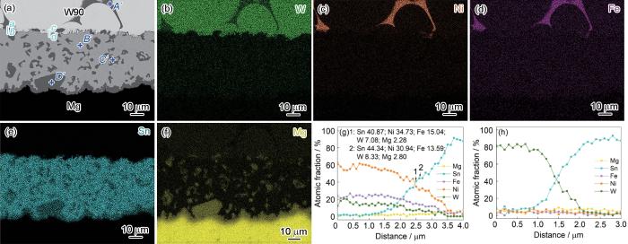
图2
100 W超声功率下W90/Sn/Mg接头横截面微观组织的SEM像及EDS分析
(a) typical interface microstructure
(b-f) EDS mappings of W (b), Ni (c), Fe (d), Sn (e), and Mg (f)
(g, h) EDS line scanning results along lines ab (b) and cd (c) in Fig.2a
Fig.2
Cross-sectional SEM image (a) and EDS results (b-h) of the W90/Sn/Mg joint under an ultrasonic power of 100 W
表1 图2中标记点的化学成分及相种类 (atomic fraction / %)
Table 1
| Position | Sn | Mg | W | Ni | Fe | Phase type |
|---|---|---|---|---|---|---|
| A' | 0.01 | 0.03 | 10.54 | 64.23 | 25.19 | (Ni, Fe) phase |
| B' | 99.82 | 0.11 | 0.02 | 0.03 | 0.02 | β-Sn |
| C' | 30.98 | 68.97 | 0.01 | 0.03 | 0.01 | Mg2Sn |
| D' | 29.30 | 70.65 | 0.01 | 0.03 | 0.01 | Mg2Sn |
2.2 超声功率对W90/Sn/Mg接头微观组织的影响
图3为不同超声功率下W90/Sn/Mg接头的SEM像。可以看出,在不同超声功率下,钎焊接头界面处均未出现裂纹、空洞和未焊合等缺陷。随着超声功率的增加,焊缝宽度逐渐减小,界面Mg2Sn层厚度逐渐增加。当超声功率为150 W时,焊缝中出现块状的Mg2Sn化合物;当超声功率为200 W时,焊缝中未观察到块状Mg2Sn化合物,但部分Mg2Sn层生长至W90钨合金侧。
图3

图3
不同超声功率下W90/Sn/Mg钎焊接头微观组织的SEM像
(a) 50 W (b) 150 W (c) 200 W
Fig.3
SEM images of the microstructures of W90/Sn/Mg joints under various ultrasonic powers
2.3 超声功率对W90/Sn/Mg接头力学性能的影响
图4为W90/Sn/Mg接头的抗剪强度随超声功率的变化。可见,随着超声功率的增加,接头抗剪强度呈梯形变化趋势。当超声功率为100和150 W时,接头的抗剪强度达到最大值10.5 MPa。为了分析接头的断裂位置,对剪切实验后的W90钨合金断裂面进行观察,如图5所示。随着超声功率的增加,接头的断裂位置从Sn/W90界面转变为Mg2Sn层。当超声功率为50 W时,接头的断裂位置在Sn/W90界面处,断口表面观察到少量的Sn;当超声功率增加至100 W时,接头的断裂位置不变,断口表面的Sn含量增加。结合接头强度的变化可推断,随着超声功率从50 W增加至100 W,Sn/W90界面的结合面积占比从59.6%增加至100.0%。继续增加超声功率至150 W时,接头的断裂位置和强度不变。当超声功率为200 W时,W90侧断口表面出现Mg2Sn化合物及裂纹,说明接头断裂发生在Mg2Sn层。在剪切过程中,脆性的Mg2Sn化合物作为裂纹源开裂,导致接头性能下降。
图4

图4
超声功率对W90/Sn/Mg接头抗剪强度的影响
Fig.4
Effect of ultrasonic power (P) on the shear strength (τ) of W90/Sn/Mg joint
图5

图5
不同超声功率下接头断口截面和表面的SEM像
Fig.5
Cross-sectional (a, c, e, g) and surface (b, d, f, h) SEM images of fractured W90/Sn/Mg joints under various ultrasonic powers (a, b) 50 W (c, d) 100 W (e, f) 150 W (g, h) 200 W
2.4 超声功率对钎料域内声压的影响
在超声辅助钎焊过程中,超声空化效应对固/液界面冶金反应、氧化膜的去除至关重要,而空化效应的发生则需要液态钎料中声压大于相应的空化阈值。研究[24]表明,纯Sn在250 ℃的空化阈值约为1.26 MPa。
为了分析钨合金与镁合金超声辅助钎焊过程中,液态Sn中声压的变化情况,采用有限元模拟软件,模拟液态Sn中的声压变化。图6展示了超声辅助钎焊过程中液态Sn在超声开启后9 cyc内的声压变化特征,所选择的超声功率为100 W,相应的超声振幅为1.1 μm,图中正弦曲线为施加超声的周期。可以看出,施加超声后,即第8 cyc结束时,液态Sn内部的声压为正,最大压力为16.4 MPa;最大声压在液态Sn中心位置获取,声压向四周逐渐降低。0.2 cyc后,液态Sn中声压变为负值,最大声压绝对值达4.5 MPa;0.5 cyc后,液态Sn的声压又变为正值(15.5 MPa)。在一个超声周期内,液态Sn中的声压经历正值-负值-正值-负值的周期性变化。这是因为声波在传播到液/固界面时发生反射,反射的声波与入射声波相互耦合作用,导致液态Sn中声压发生增强或削弱,声压变化的频率增加。
图6

图6
9 cyc内液态Sn中声压变化
(a) 400 μs (b) 410 μs (c) 415 μs (d) 425 μs
(e) 430 μs (f) 435 μs (g) 445 μs (h) 450 μs
Fig.6
Variations of acoustic pressures within the 9 cyc at different time
为了进一步了解液态Sn中声压的变化情况,提取特征点A和B,其坐标分别为(4.50, 4.50, 5.15)和(6.75, 6.75, 5.15),分析其在0~12 cyc内声压的变化情况,结果如图7所示。可以看出,在相邻周期内,特征点的声压幅值不同;在相同的时间下,特征点A的声压大于特征点B。
图7
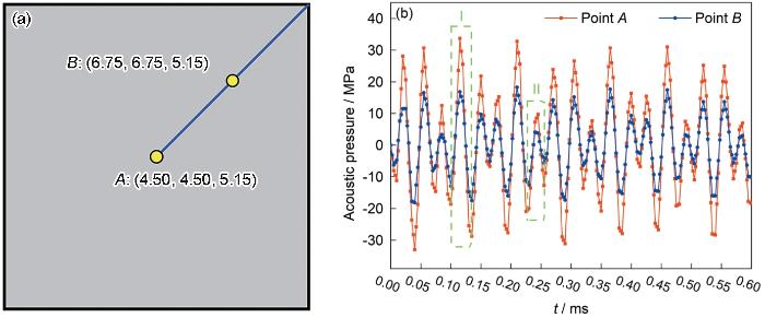
图7
0~12 cyc内特征点A与B声压值对比
(a) coordinates of points A and B
(b) acoustic pressure distribution
Fig.7
Comparison of acoustic pressure of points A and B within 0-12 cyc (t—time; regions I and II represent the maximum and minimum acoustic pressure amplitudes at points A and B, respectively)
式中,c为声速;R为空化泡半径;t为时间;ρ为密度;P1为空化壁所受的压力合力;P0为空化泡外初始压力,通常为大气压力;σ为表面张力;R0为空化泡初始半径;k为绝热指数;Pv为蒸气压;μ为运动黏度;PA为声压幅值;f为施加的超声频率。
图8

图8
空化泡动力学分析
(a) Solution R(t) / R0 within two acoustic periods (R(t)—radius of cavitation bubble at time t, R0—initial radius of cavitation bubble)
(b) collapse velocities (dR / dt) of the bubble wall
(c) variations of temperature (T) with t of bubble collapse
(d) variations of pressure (P1) with t of bubble collapse
Fig.8
Bubble dynamics analyses
根据Noltingk-Neppiras“热点理论”[27],计算出空化效应产生的温度和压力,其中k取4/3:
式中,T为空化泡崩溃产生的温度,T0为钎焊温度(523.15 K)。
上述计算结果表明,空化效应的强度与液态Sn中的声压紧密相关。图9为超声功率对特征点A声压的影响,50、100、150和200 W超声功率分别对应了0.8、1.1、2.3和3.2 μm超声振幅。可以看出,特征点A的声压随着超声功率的增加而增加,表明提高超声功率可以增强超声空化效应,产生更强的高温、高压、微射流和冲击波。因此,钨合金与Sn的反应更快,镁合金侧Mg2Sn化合物的生长更快。
图9
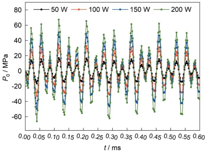
图9
超声功率对特征点A声压的影响
Fig.9
Effect of ultrasonic power on the acoustic pressure of point A
2.5 W90/Sn/Mg接头形成机理
根据上述实验结果与分析,W90/Sn/Mg接头的形成机理可以分为6个阶段。起始阶段为加热阶段,纯Sn熔化并在表面形成一层氧化膜(图10a)。当热台温度达到250 ℃时,打开超声发生器,对W90钨合金施加超声。当液态Sn中声压超过空化阈值时,发生空化效应(图10b)。在固/液界面产生了高温、高压、微射流和冲击波,微射流和冲击波击碎了氧化层,促进镁合金与液态Sn接触发生冶金反应;高温、高压形成的非平衡环境促进纯Sn在W90钨合金表面的润湿铺展(图10c)。当镁合金与液态Sn表面的氧化膜完全去除后,(Ni, Fe)黏结相中的Ni元素与Sn元素结合形成了Ni3Sn4化合物;Mg元素扩散进入液态Sn中,当焊缝中的Mg元素浓度达到一定程度后逐渐以Mg2Sn化合物的形式析出;同时镁合金侧生成一层Mg2Sn层(图10d和e)。在冷却阶段,Mg2Sn层逐渐变厚,Mg元素通过Mg2Sn层扩散进入钎缝中,钎缝中的Mg2Sn化合物逐渐长大,当温度降至室温后,形成W90/Sn/Mg接头(图10f)。
图10

图10
接头形成机理图
(a) heating process (b) applying ultrasound (c) cavitation effect
(d) elemental diffusion (e) turning off ultrasound (f) cooling process
Fig.10
Schematics of formation mechanism of joint
超声是以位移的方式施加在钨合金表面的,不同的超声功率代表着不同的位移。随着超声功率的增加,超声产生的位移逐渐增加,被挤出焊缝的液相Sn增多,导致焊缝宽度减小。同时,超声功率的增加,导致液相Sn中声压幅值增加,界面处产生更剧烈的空化效应,Sn/W90界面结合面积占比从59.6%增加至100.0%,W90/Sn/Mg接头的抗剪强度增加。当超声功率达到100 W时,Sn/W90界面结合面积达到100%,W90/Sn/Mg接头的抗剪强度达到最大值,继续增加超声功率时,接头的强度不会增加。当超声功率达到200 W时,接头的抗剪强度减小,这是由于Mg侧Mg2Sn化合物层较厚,接头在此处发生断裂。
3 结论
(1) 在空气条件下,采用纯Sn实现W90钨合金与AZ31B镁合金的超声辅助钎焊连接,接头界面结合良好,无孔洞及裂纹。焊缝的典型微观组织为(Sn + Mg2Sn)/Mg2Sn双层结构。随着超声功率的增加,焊缝宽度减小,Mg2Sn层厚度增加。
(2) 随着超声功率的增加,接头抗剪强度呈现先增加后下降的趋势。当超声功率为100和150 W时,接头的抗剪强度达到最大值10.5 MPa。
(3) 在超声辅助钎焊过程中,液态Sn中的声压幅值呈周期性变化,任意位置的声压呈正弦变化。随着超声功率的增加,液态Sn中同一位置同一时间的声压增加,空化泡产生的空化效应更强。
参考文献
A first principles investigation of W1 - x Ir x alloys: Structural, electronic, mechanical, and thermal properties
[J].
W1 - x Ir x 固溶合金几何结构、电子结构、力学和热力学性能的第一性原理计算
[J].
Surface microstructural alterations and grain refinement mechanisms of tungsten heavy alloys by thermo-mechanical coupling: A laser-assisted milling case
[J].
Microstructure evolution mechanism of new low-alloyed high-strength Mg-0.2Ce-0.2Ca alloy during extrusion
[J].
新型低合金化高强Mg-0.2Ce-0.2Ca合金挤压过程中的组织演变机理
[J].
Interfacial microstructure and mechanical properties of indirect brazed graphite/copper joint
[J].
石墨/紫铜间接钎焊接头的界面组织及力学性能
[J].
Microstructure and properties of brazed W-W joints by Ti-35Ni alloy
[J].
Effect of Ni-Ti filler on brazed W-Cu/18-8 joints
[J].
Brazing of tungsten based alloy/superalloy GH907 with lean Cu-Ag based fillers: Wetting, interfaces and performance evaluation
[J].
Brazing W and Fe-Ni-Co alloy using Ag-28Cu and Ag-27Cu-3.5Ti fillers
[J].
Development of a Mg-Al filler metal for brazing magnesium alloy AZ31B
[J].
Interface characteristics and mechanical properties of the induction brazed joint of magnesium alloy AZ31B with an Al-based filler metal
[J].
Microstructure and mechanical properties of magnesium alloy AZ31B brazed joint using a Zn-Mg-Al filler metal
[J].
Control Al/Mg intermetallic compound formation during ultrasonic-assisted soldering Mg to Al
[J].
Study on low temperature brazing of magnesium alloy to aluminum alloy using Sn-xZn solders
[J].
Improving weld strength of arc-assisted ultrasonic seam welded Mg/Al joint with Sn interlayer
[J].
Molecular dynamics simulation on the interfacial behavior of Mg-Zn-Al/Mg brazing with ultrasonic assistance
[J].
超声辅助下Mg-Zn-Al/Mg钎焊界面行为的分子动力学模拟
[J].
In-situ formation of amorphous Al2O3 interphase during ultrasonic-assisted soldering process of ZrO2 ceramic and 1060Al using Sn filler at low temperature
[J].
Room-temperature direct bonding of ZrO2 ceramic and SiCP/Al composite using ultrasonic waves
[J].
Interfacial microstructure and mechanical properties of ultrasonic-assisted brazing joints between Ti-6Al-4V and ZrO2
[J].
Comparisons of spark-charge bubble dynamics near the elastic and rigid boundaries
[J].
Study on the spatial distribution of the liquid temperature near a cavitation bubble wall
[J].
Shock wave emission and cavitation bubble dynamics by femtosecond optical breakdown in polymer solutions
[J].
Comfort and quality of life of cancer patients
[J].
Sonochemical hot spot
[J].
Cavitation dynamics and its application during ultrasonic-assisted soldering
[D].
超声波钎焊过程中声空化动力学及其应用研究
[D].
Dependence of wetting on cavitation during the spreading of a filler droplet on the ultrasonically agitated Al substrate
[J].
Evolution behavior of cavitation bubble in pure Sn liquid medium with narrow gap under low-amplitude ultrasound
[J].
Research on interfacial bonding mechanism and process of ultrasonic assisted active soldering SiC ceramic
[D].
SiC陶瓷超声辅助活性软钎焊界面结合机理及工艺研究
[D].
On the pressure of cavitation bubbles
[J].
On the governing fragmentation mechanism of primary intermetallics by induced cavitation
[J].


