


Cu-Ni-Si合金因其高强、高导以及优异的抗应力松弛等性能,被公认为极具潜力的新一代引线框架材料[1,2]。随着工业材料向优异综合性能的方向发展,单一铜合金材料在追求更高强度的同时往往面临延伸率下降及成本高昂的制约,不能满足性能要求。相比之下,1010低碳钢以其低廉的价格、优异的成形性和良好的强度,在汽车、家电和建筑等领域应用广泛[3]。为了突破单一金属的性能瓶颈,使材料同时兼具多种优异的性能,双金属复合材料应运而生[4,5]。将Cu-Ni-Si合金与1010钢通过一定的方式制备成双金属复合材料,能够实现材料性能的优势互补,即利用Cu-Ni-Si合金的高强度、导热性及耐磨性,以及钢的强度、刚度和经济性,从而满足材料的性能需求[6,7]。
尽管双金属复合材料应用前景广阔,但在制备和工艺控制方面仍面临严峻挑战,其核心问题在于异种金属界面的结合质量。双金属复合材料的制备方法可概括为固-固复合法、固-液复合法和液-液复合法,其中使用最广泛的方法是固-液复合法,其界面结合强度主要依赖于液态合金与固态基体之间发生的元素互扩散和物理结合[8,9]。然而,在铜/钢双金属复合材料体系中,由于Cu与Fe具有较大的正混合焓,在热力学上互溶度极低,难以发生广泛的相互扩散并形成强冶金结合,导致铸态样品的界面结合通常较弱[10]。更重要的是,铸态组织本身较为粗大[6],且界面易存在缺陷[11]、裂纹及氧化物[12]等缺陷,这些因素严重制约了界面力学性能进一步提升。因此,如何通过合适的后续加工工艺调控微观组织及力学性能,成为该类双金属复合材料走向工程应用的关键。
目前,热处理和塑性变形是调控金属材料组织和性能的两种主要手段。直接退火处理,可以消除部分内应力[13],并促进界面原子扩散,从而在一定程度上改善材料性能[14,15],但无法从根本上改变铸态组织粗大的形貌,且强化作用有限。相比之下,轧制能够引入巨大的塑性应变,一方面可以破碎粗大的铸态组织,使材料致密化[16];另一方面,较大的三向压应力能迫使两层金属产生剧烈的塑性流动,冲破表面氧化层的阻碍,实现界面的新鲜金属接触和机械咬合,为原子提供高扩散通道,从而显著提高界面结合强度[17,18]。然而,单纯的强变形会导致材料塑性急剧下降。轧制后的退火处理,则可以在消除部分加工硬化的同时,通过促进原子跨界面扩散,形成更稳固的冶金结合,最终获得细小、均匀的微观组织[19~21]。Xu等[22]对Ti/Al/Cu复合材料进行冷轧+退火处理,显著提高了双金属的强度。因此,探索合适的“冷轧+退火”的协同工艺,利用形变储能诱导再结晶或析出相变,同时通过退火促进界面冶金反应,成为获得高强韧双金属复合材料的潜在突破口。尽管关于铜/钢双金属复合材料的轧制工艺已有研究,但针对Cu-Ni-Si/1010钢这一特定体系,目前尚缺乏系统性的研究。
基于此,本工作研究了直接退火及轧制+退火工艺对Cu-Ni-Si/1010钢双金属复合材料微观组织、力学性能和断裂行为的影响规律。通过对Cu-Ni-Si侧和1010钢侧的晶粒形貌、尺寸及析出特征进行表征,探究了其组织演化规律;同时,通过对材料力学性能的综合评估,揭示了加工硬化、析出强化与异质变形诱导(HDI)强化的协同机理,为高性能Cu-Ni-Si/钢双金属复合材料的工艺优化提供了实验依据和应用参考。
1 实验方法
1.1 试样制备
双金属复合材料的基层选用1010钢,在与Cu-Ni-Si合金复合之前,钢板需经过折弯、打磨和酸洗处理,之后利用无水乙醇进行清洗。1010钢的初始组织主要由平均晶粒尺寸为10~20 μm的铁素体和珠光体构成,试样尺寸为3500 mm × 140 mm × 3.5 mm。覆层材料为Cu-2.3Ni-0.5Si (质量分数,%)合金。采用XRF-1800 X射线荧光光谱仪对两种材料的实际化学成分进行标定,结果列于表1。
表1 Cu-Ni-Si合金和1010钢的主要化学成分 (mass fraction / %)
Table 1
| Material | C | Si | Mn | Cr | Ni | Cu | Fe |
|---|---|---|---|---|---|---|---|
| Cu-Ni-Si | - | 0.50 | - | - | 2.10 | Bal. | - |
| 1010 steel | 0.09 | 0.36 | 0.40 | 0.10 | - | - | Bal. |
图1为Cu-Ni-Si/1010钢双金属复合材料制备工艺路线、不同后处理工艺及力学性能测试所用试样尺寸的示意图。复合板的制备过程如下:首先,将经过打磨和酸洗处理的1010钢板置于高频电磁感应线圈中预热至1000 ℃。随后,在牵引装置驱动下,预热后的钢板开始向前匀速移动。与此同时,将Cu-Ni-Si原料(包括电解Cu (≥ 99.95%,质量分数,下同)、工业纯Si (≥ 99.5%)和工业纯Ni (≥ 99.95%))在另一电磁感应熔炼炉中加热至1300 ℃,并保温5 min,随后将熔融的Cu-Ni-Si熔体浇注至匀速运动的预热钢板表面。在钢板底部设置有多道次的冷却水装置,通过强制水冷使覆层铜合金与基层钢板迅速同步冷却至室温。此快速冷却过程旨在利用较大的过冷度促进界面结合,并获得细小的凝固组织。为了防止金属材料在高温下氧化,从钢板预热、浇注复合到最终冷却的整个工艺流程均在Ar气保护下进行。通过这种连续固-液复合法,最终成功制备出平均总厚度约为10 mm的双金属复合板,其中1010钢基层厚度约为3.5 mm,Cu-Ni-Si覆层厚度约为6.5 mm。采用慢走丝电火花线切割从双金属板上截取所需形状的试样。随后,对这些试样进行不同工艺处理:铸态样品作为基准样品,不进行任何后续热处理,记为S1;直接在450 ℃进行退火的双金属样品记为S2;将冷轧(变形量70%)随后再进行450 ℃退火处理的双金属样品记为S3;为更加清楚地解释轧制+退火强化机制,将冷轧70%的双金属样品作为另一对照组,记为S4。
图1

图1
固-液复合法制备Cu-Ni-Si/1010钢双金属层状复合材料、不同后处理工艺及力学性能测试所用试样尺寸的示意图
Fig.1
Schematics of Cu-Ni-Si/1010 steel laminated bimetallic composites prepared by solid-liquid bonding, different post-processing processes, and specimen size for mechanical property testing (unit: mm)
1.2 微观组织表征
利用MEF-4A金相显微镜(OM)和Supra 55场发射扫描电子显微镜(SEM)对S1~S4样品的微观组织形貌进行观察。为了揭示更微观的亚结构,采用Model EM-002B透射电子显微镜(TEM)进行析出相表征,薄区样品利用聚焦离子束(FIB)技术制备。利用JXA-8530 F PLUS电子探针显微分析仪(EPMA)对界面中的主要元素进行线分布扫描,以直观展示其元素分布。借助SEM附带的电子背散射衍射(EBSD)系统分析晶体取向、统计平均取向差,并计算平均晶粒尺寸和几何必需位错密度。金相样品的制备步骤为:首先对复合板试样进行标准的磨抛处理以获得无划痕的镜面,分别使用5 g FeCl3 + 5 mL HCl + 90 mL C2H5OH和4%HNO3 + 96%C2H5OH (体积分数)混合溶液对Cu-Ni-Si合金和1010钢进行腐蚀。
1.3 力学性能测试
利用HV-10MP显微硬度计进行显微硬度测试,实验载荷为2.9 N,保载时间为15 s。为获取可靠的硬度分布数据,在垂直于界面方向的Cu-Ni-Si侧和1010钢侧均以250 μm为间隔进行连续打点,重复测试三次,取每次测量的算术平均值作为最终硬度。利用UTM5105电子万能试验机进行拉伸性能测试。按照如图1所示的尺寸加工板状拉伸试样。拉伸实验在室温下进行,采用0.6 mm/min的恒定横梁位移速率,直至试样断裂。记录应力-应变曲线,应力、应变均通过视频引伸计进行校正。为保障结果的统计有效性,每个工艺状态下至少测试三个有效试样,并取其平均值作为最终结果。拉伸测试后,利用SEM观察断口表面形貌。
2 实验结果
图2为S1~S4样品中Cu-Ni-Si侧、1010钢侧以及双金属界面结合区显微组织的OM像。S1和S2样品中Cu-Ni-Si合金侧均以粗大的柱状晶为主,呈现典型的铸态组织,表明凝固过程因快速冷却导致晶粒定向生长;S3样品中Cu-Ni-Si侧的部分晶粒则呈现纤维状组织,表明部分晶粒经冷轧变形及450 ℃退火处理后未完全再结晶,保留了轧制诱导的变形结构;相比之下,S4样品中的Cu-Ni-Si侧则表现为更强烈的变形组织。S1和S2样品的界面平直连续、无裂纹或孔洞;而S3和S4样品的界面呈现明显弯曲形态,这表明冷轧界面经历了明显的塑性变形。对于1010钢侧,S1和S2样品均保持典型的铁素体、珠光体和少量贝氏体组织;S3样品仍保留变形结构,验证了钢基体在该温度下的热稳定性;S4样品的晶粒显著拉长。图3为S1~S4样品界面线扫结果。可见,在双金属界面区域,四种样品均未观察到明显的金属间化合物,表明界面通过元素扩散形成连续的扩散层,避免了脆性相的形成,这有利于界面结合强度的提高[23]。
图2

图2
S1~S4样品Cu-Ni-Si侧、界面区域及1010钢侧微观组织的OM像
Fig.2
OM images of samples S1 (a1-a3), S2 (b1-b3), S3 (c1-c3), and S4 (d1-d3) (The as-cast sample served as the reference specimen without any subsequent treatment, labeled as S1. The bimetallic laminated composite directly annealed at 450 oC was labeled as S2. The bimetallic laminated composite subjected to cold rolling with the 70% reduction ratio followed by annealing at 450 oC was labeled as S3. To elucidate the strengthening mechanism of rolling + annealing more clearly, the bimetallic laminated composite with only 70% cold rolling was included as an additional control group, labeled as S4) (a1-d1) Cu-Ni-Si alloy sides (a2-d2) interface regions (a3-d3) 1010 steel sides
图3

图3
S1~S4样品界面处的EPMA线扫描结果
Fig.3
EPMA line scan results at the interfaces of samples S1 (a), S2 (b), S3 (c), and S4 (d)
图4为S1~S4样品界面附近的EBSD分析结果。在S1样品中,Cu-Ni-Si侧粗大的柱状晶沿[001]方向择优生长,平均晶粒尺寸达124.9 μm;1010钢为细小等轴晶组织,晶粒尺寸主要分布于5~20 μm,平均晶粒尺寸为14.0 μm,组织均匀,无明显织构。对于直接退火后的S2样品,Cu-Ni-Si侧仍保持柱状晶形貌,取向未发生变化,平均晶粒尺寸略增至130.2 μm,表明发生轻微晶界迁移;1010钢组织无明显变化,平均晶粒尺寸为14.1 μm,进一步表明450 ℃下未发生相变或再结晶。冷轧+退火态的S3样品组织显著细化,对比S4样品可以看出,退火处理后两侧合金均未发生完全再结晶。S3和S4样品Cu-Ni-Si侧的原始柱状晶破碎,晶粒取向趋于沿轧向排列,表现出明显的冷轧织构特征,其平均晶粒尺寸大幅减小至2.2和1.9 μm,反映出剧烈塑性变形诱导的晶粒细化效应,产生的亚结构不仅直接贡献加工硬化,还为退火过程中δ-Ni2Si相提供了大量异质形核位置,有利于析出相的细小、弥散分布。与此同时,1010钢侧也受到显著变形的影响,晶粒被压扁并沿轧向延伸,形成平行排列的带状结构,其平均晶粒尺寸均进一步细化至0.9 μm,表明冷轧应力有效传递至钢侧,促使其发生塑性变形。
图4

图4
S1~S4样品界面附近Cu-Ni-Si合金侧和1010钢侧的反极图及对应的晶粒尺寸分布图
Fig.4
EBSD analysis results of samples S1-S4 near the interface (a1-d1) inverse pole figures (IPFs) of Cu-Ni-Si side in samples S1 (a1), S2 (b1), S3 (c1), and S4 (d1) (a2-d2) grain size distribution histograms corresponding to Figs.4a1-d1, respectively (a3-d3) IPFs of 1010 steel side in samples S1 (a3), S2 (b3), S3 (c3), and S4 (d3) (a4-d4) grain size distribution histograms corresponding to Figs.4a3-d3, respectively
由于1010钢在450 ℃下无相变发生,因此主要关注Cu-Ni-Si合金组织。图5为S1~S4样品中Cu-Ni-Si合金的XRD谱。S1样品中,除α-Cu相外,β-Ni3Si相衍射峰清晰可见,表明凝固过程中冷却速率未达到形成单相固溶体的条件,β-Ni3Si相已优先析出。经450 ℃退火处理的S2样品中,可观察到δ-Ni2Si相衍射峰,同时仍然存在β-Ni3Si相的衍射峰,表明退火处理促进了Ni与Si元素的扩散反应,诱导了δ-Ni2Si相析出。值得注意的是,S4和S1样品的物相组成相同,但S3样品呈现截然不同的特征:δ-Ni2Si相的衍射峰强度减弱,这可能与其析出相尺寸更加细小有关,同时α-Cu相(111)峰显著宽化且(200)峰相对增强,表明冷轧引入的高密度位错导致晶格畸变和择优取向改变。冷轧+退火通过加速Ni原子扩散,为δ-Ni2Si相的形成提供更多的形核位点并抑制其生长,同时使β-Ni3Si相保持稳定。
图5

图5
S1~S4样品中Cu-Ni-Si合金的XRD谱
Fig.5
XRD patterns of Cu-Ni-Si alloy in samples S1-S4
为了确定析出相的分布和类型,利用TEM观察了S1~S3样品中Cu-Ni-Si合金的组织形貌。图6a~c分别为S1样品中Cu-Ni-Si基体的TEM明场像、高分辨TEM (HRTEM)像和析出相的TEM明场像及其选区电子衍射(SAED)花样。可以看出,基体中只观察到α-Cu相;在α-Cu的晶界处观察到长条状β-Ni3Si相,尺寸约为200 nm。因此,未退火Cu-Ni-Si合金的显微组织由α-Cu和β-Ni3Si相组成。图6d~f为S2样品中Cu-Ni-Si基体的TEM表征结果。可以看出,α-Cu基体中析出小颗粒状δ-Ni2Si相。这与Wang等[24]的实验结果一致,表明在Cu-Ni-Si合金退火处理过程中,δ-Ni2Si相因其形成焓最低而率先析出。β-Ni3Si相同样存在于α-Cu的晶界处,表明其形态和分布在退火过程中保持不变,退火后的组织为α-Cu + δ-Ni2Si + β-Ni3Si。S3样品的TEM表征结果如图6g~i所示,δ-Ni2Si相数量相比于S2样品明显增多,同时β-Ni3Si相未因轧制处理而发生改变,因此结合图5的XRD结果可知,S3样品Cu-Ni-Si中的组织也为α-Cu + δ-Ni2Si + β-Ni3Si。
图6

图6
S1~S3样品中Cu-Ni-Si基体和析出相的TEM表征
Fig.6
TEM characterizations of Cu-Ni-Si matrix and precipitation phases in samples S1 (a-c), S2 (d-f), and S3 (g-i) (a, d, g) bright field TEM images of Cu-Ni-Si matrix (b, e, h) HRTEM images of square areas in Figs.6a, d, and g, respectively (Insets in Figs.6b and e show the corresponding SAED patterns) (c, f) bright field TEM images of precipitation phases at grain boundary (Insets show the corresponding SAED patterns) (i) TEM image and corresponding EDS element distribution maps of sample S3
为揭示处理工艺对Cu-Ni-Si/1010钢双金属复合材料硬度分布的影响,图7给出了S1~S4样品从Cu-Ni-Si侧到1010钢侧的显微硬度分布曲线和平均硬度。图7a中,负值表示Cu-Ni-Si侧,正值表示1010钢侧,坐标原点定义为界面中心。在Cu-Ni-Si侧,S1样品的平均硬度约为107.7 HV,呈轻微波动趋势,反映出铸态组织中晶粒粗大且析出相析出不充分,强化效果有限;经450 ℃退火处理后,S2样品的硬度提升至约129.6 HV,表明δ-Ni2Si相的形成显著增强了Cu-Ni-Si合金的硬度;经70%冷轧变形及450 ℃退火处理,S3样品的平均硬度进一步增加至约180 HV,远高于S1、S2和S4样品,说明冷轧引入的高密度位错及加工硬化效应与退火产生的析出强化协同作用,实现了“形变-析出”双重强化。在界面区域,所有样品均表现出明显的硬度突增,其中S3样品的界面峰值硬度达到约215.1 HV,明显高于S1 (148.7 HV)、S2 (138.1 HV)和S4 (201.7 HV)样品,表明冷轧和退火处理共同优化了界面处的微观结构,促进了元素扩散及细小析出相的均匀分布,提升了界面结合强度。在1010钢侧,S1和S2样品的硬度均维持在140~160 HV之间,变化平缓,证实该温度下钢基体未发生相变或再结晶,组织稳定;S3和S4样品因冷轧导致晶粒拉长及位错积累,其钢侧硬度相近,说明退火对钢硬度的影响较小。
图7

图7
S1~S4样品从Cu-Ni-Si侧到1010钢侧的硬度分布曲线和平均硬度
Fig.7
Microhardness distribution curves (a) and average microhardnesses (b) of samples S1-S4 in Cu-Ni-Si side, 1010 steel side, and interface (The negative values of position in Fig.7a indicate the Cu-Ni-Si side, positive values indicate the 1010 steel side, and the coordinate origin “0.0” is defined as the center of the interface, respectively)
图8a为S1~S4样品的拉伸应力-应变曲线,图8b为对应的抗拉强度(UTS)、屈服强度(YS)和延伸率(EL)汇总图。S1样品的EL为25.4%,虽然呈现较为优异的塑性,但其YS和UTS较低,仅分别为233和379 MPa,不能满足高强度的需求。S2样品的YS达到261 MPa, UTS提升至415 MPa,表明δ-Ni2Si相的析出增强了材料强度,同时对位错运动产生一定阻碍。S2样品的EL略有升高,达到27.7%,与S1样品相比增大了约9.1%,这主要归因于1010钢在退火过程中发生的回复作用,1010钢塑性的增强也使S2样品整体塑性增强。S4样品的强度明显提高,但同时塑性也大幅度下降至12.6%。S3样品表现出最优的综合力学性能:YS为501 MPa,UTS为613 MPa,尽管EL降至18.4%,但仍保持良好的塑性变形能力。S3样品的应力-应变曲线显示出其具有明显的加工硬化能力,且峰值应力显著高于S1和S2样品,这主要归因于冷轧引入的高密度位错网络在退火处理过程中促进δ-Ni2Si相优先析出,形成更细小且分布均匀的析出相,从而实现更强的Orowan强化效果。此外,冷轧导致的晶格畸变和择优取向改变进一步提高了基体强度。综上所述,冷轧+退火协同处理工艺显著优化了Cu-Ni-Si/1010钢双金属层状复合材料的微观组织,实现了强度与塑性的良好平衡。
图8
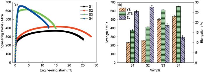
图8
S1~S4样品的拉伸性能
Fig.8
Tensile properties of samples S1-S4
(a) engineering stress-strain curves
(b) average yield strength (YS), ultimate tensile strength (UTS), and elongation (EL)
图9为S1~S4样品断口表面形貌的SEM像。所有样品在断裂过程中均未出现界面分层现象,表明界面结合良好。S1和S2样品断口中1010钢侧表现为典型铁素体基体上的等轴韧窝,尺寸均匀、分布密集,反映出良好的塑性变形能力;S3样品断口中1010钢侧虽仍可见韧窝,但其尺寸明显减小、深度变浅,部分区域呈现撕裂棱与微孔连接的过渡形貌;S4样品断口出现大面积的无韧窝区,表明冷轧引入的高密度位错限制了其塑性变形能力,整体塑性有所下降。另外,S1样品的Cu-Ni-Si侧呈现尺寸较大、分布不均的韧窝,反映出铸态组织具有一定的塑性变形能力。尽管界面区域未发生脱黏,但局部存在微孔聚集和较深的韧窝,说明裂纹萌生于基体内部。S2样品的断口形貌显示,韧窝明显细化且分布更均匀,表明热处理促进了δ-Ni2Si相的形成,界面处断裂表面更加平滑,进一步证实热处理优化了界面元素扩散,提升了结合质量。S3样品断口的Cu-Ni-Si侧韧窝数量显著减少,局部区域出现平坦的解理面,表现出脆性断裂倾向,而S4样品以脆性断裂为主。本工作的退火温度不足以充分回复冷轧缺陷,使材料在拉伸过程中更易沿特定晶面发生脆性开裂。尽管如此,界面区域仍未观察到分层或脱黏,断裂路径仍贯穿界面,表明即使在脆性倾向增强的条件下,冷轧+退火处理工艺仍能维持良好的界面冶金结合。
图9

图9
S1~S4样品断口表面形貌的SEM像
Fig.9
Low (a, c, e, g) and high (b, d, f, h) magnified SEM images showing the fracture surface morphologies of samples S1 (a, b), S2 (c, d), S3 (e, f), and S4 (g, h)
3 分析与讨论
3.1 组织演变
为了分析Cu-Ni-Si/1010钢双金属复合材料在退火处理过程中的相变行为和组织演化规律,利用Pandat软件对合金相图进行计算,结果如图10所示。图10a为Cu-Ni-xSi体系伪二元相图。可以看出,当Si含量约为0.5%时,合金成分位于fcc + Ni2Si + Ni5Si2三相区,然而,由于Cu-Ni-Si合金的冷却方式为非平衡冷却,冷却速率较快,导致其实际相组成在伪二元相图中向低Si含量方向偏移,同时冷却速率又不足以使其形成单相固溶体,因此S1样品中Cu-Ni-Si合金呈现α-Cu和β-Ni3Si两相。在退火过程中发生近似平衡转变,该成分在450 ℃处于稳定析出温度区间,对应图5中δ-Ni2Si相的形成,表明退火处理过程中Ni与Si原子扩散并发生共沉淀反应,生成热力学稳定的Ni2Si析出相,这在Hu等[25]的研究中已被证实。冷却过程相转变曲线和450 ℃等温相图分别如图10b和c所示,表明此过程并未形成其他沉淀相,δ-Ni2Si是最主要的强化相。图10d为Fe-C二元相图。可以看出,C含量约为0.1%的1010钢,其成分位于bcc + Fe3C两相区,而450 ℃远低于共析转变温度(727 ℃),因此1010钢仍保持铁素体和珠光体结构,未发生奥氏体化或相变,这与图2的金相观察结果一致,即所有样品中钢侧组织的组成均未发生变化。综合相图分析结果可知,在450 ℃热处理条件下,Cu-Ni-Si合金发生析出强化,而1010钢基体组织保持稳定。表明450 ℃退火处理对双金属体系的作用具有选择性:在Cu-Ni-Si侧促进析出强化,在钢侧则维持原始组织,从而在不损害界面结合的前提下实现复合材料强度提升。
图10

图10
Cu-Ni-xSi伪二元相图、Cu-Ni-Si相转变曲线、Cu-Ni-Si 450 ℃等温相图及Fe-C二元相图
Fig.10
Cu-Ni-xSi pseudo-binary phase diagram (a), Cu-Ni-Si phase transition curves (b), Cu-Ni-Si isothermal phase diagram at 450 oC (c), and Fe-C binary phase diagram (d)
3.2 强化机制
3.2.1 基体强化
在S1样品中,Cu-Ni-Si合金侧呈现粗大柱状晶,硬度较低,说明铸态组织缺乏有效强化手段。尽管快速凝固促使少量β-Ni3Si相在晶界析出,但其粒径较大、数量较少,对位错运动阻碍有限,强化效果微弱。同时,粗大柱状晶使得细晶强化作用可忽略,且S1样品未经历变形,不存在加工硬化。因此固溶强化是唯一有效机制。由于凝固过程中冷却速率较快,Ni和Si原子未能充分析出,大部分仍固溶于α-Cu基体中。然而,Cu和Ni的晶体结构相近[29],Ni原子引起的晶格畸变较小,导致强化增量有限,仅有Si元素能提供少量的固溶强化作用。因此,S1样品的强度主要来源于1010钢侧的本征强度和HDI强化[30],整体性能受限于Cu-Ni-Si层的软化状态。
S2样品经过了450 ℃退火处理,强度显著提升,其核心机制由析出强化主导。TEM结果证实,退火处理促使Ni和Si原子扩散,形成大量纳米尺度的δ-Ni2Si相,弥散分布于α-Cu基体中。δ-Ni2Si相具有低形成焓和高热力学稳定性,在450 ℃下优先析出,通过Orowan绕过机制强烈阻碍位错运动,绕过机制的强度增量(Δτ)可用下式计算[31]:
式中,α为常数,dp为析出相的平均距离,fv为析出相的体积分数。由此可知,析出相越密集、数量越多,强化效果越明显。值得注意的是,450 ℃下Cu-Ni-Si合金未发生再结晶,晶粒仍为粗大柱状,说明强度提高基本源于析出相的贡献,而非晶粒细化或位错强化。而1010钢侧因组织稳定,未参与强化过程,S2样品的强度提高主要来源于Cu-Ni-Si合金的析出强化。同时,对于双金属复合材料,整体塑性受限于塑性较低的1010钢,退火处理能够改善其应力分布,导致其塑性提升,从而提升双金属复合材料的塑性。
式中,σ0为摩擦应力,Ky为衡量周围晶粒对流动阻力影响的Hall-Petch系数,d为平均晶粒尺寸。尽管固溶强化作用因析出而减弱,但其余三种机制的协同作用使S3样品获得远超S2和S1样品的强度水平。
图11
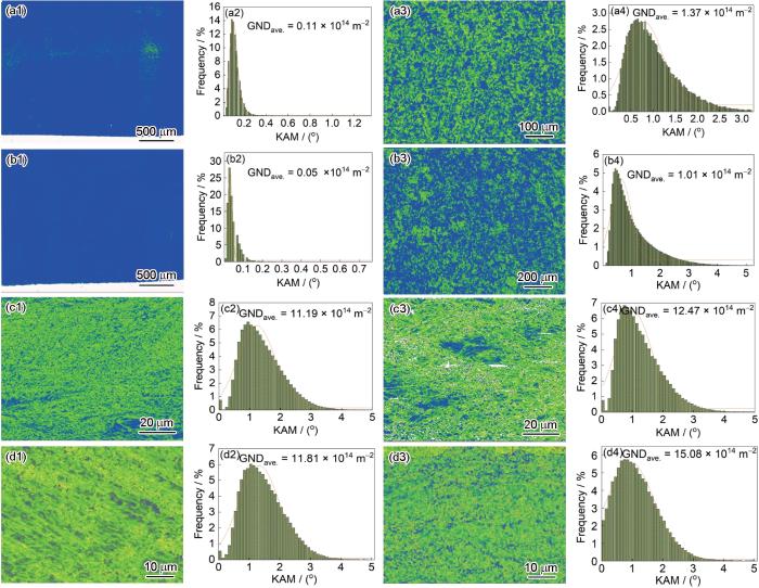
图11
S1~S4样品Cu-Ni-Si合金侧和1010钢侧的局部取向差(KAM)图及对应的几何必需位错密度分布统计图
Fig.11
Dislocation analyses of samples S1-S4 (a1-d1) kernel average misorientation (KAM) maps of Cu-Ni-Si alloy side in samples S1 (a1), S2 (b1), S3 (c1), and S4 (d1) (a2-d2) geometrically necessary dislocation (GND) density distributions corresponding to Figs.11a1-d1, respectively (GNDave.—average GND density) (a3-d3) KAM maps of 1010 steel side in samples S1 (a3), S2 (b3), S3 (c3), and S4 (d3) (a4-d4) GND density distributions corresponding to Figs.11a3-d3, respectively
3.2.2 HDI强化
对于异质双金属复合材料,HDI强化是极为重要的强化方式[33],可以利用加载-卸载-再加载拉伸曲线和迟滞回线进行计算[34]。由于S4样品的塑性较差,不能形成有效的迟滞回线,因此只对S1~S3样品进行了测试。图12为S1~S3样品的真应力-应变曲线和HDI应力随应变的演变情况。所有样品均表现出明显的Bauschinger效应,表明材料内部存在显著的残余应力场,这主要源于Cu-Ni-Si合金层与1010钢基层之间因模量和屈服强度差异而引发的非协调塑性变形。值得注意的是,S3样品的HDI应力远高于S1和S2样品,尤其在低应变阶段(约2%),S3样品的HDI应力迅速攀升至约437 MPa,充分体现了HDI强化的主导作用。这种高HDI应力源于冷轧及退火过程中两合金层间较大的硬度差异,促使界面附近积累大量几何必需位错,形成强约束的位错网络,从而显著提高材料的整体强度。相比之下,S1和S2样品因两合金层间界面平直、硬度差异较小,HDI强化贡献有限。此外,在高应变下S3样品HDI应力趋于稳定,表明异质结构已进入动态平衡的均匀变形阶段,既维持了高强度,又避免了早期局部颈缩。
图12

图12
S1~S3样品的真应力-应变曲线和异质变形诱导(HDI)应力随应变的演变
Fig.12
True stress-strain curves (a, c) and evolutions of hetero-deformation induced (HDI) stress with strain (b, d) for samples S1 and S2 (a, b) and S3 (c, d)
尽管本工作通过冷轧+退火工艺显著提升了双金属复合材料的强塑性匹配,但仍存在一定的局限性。本工作主要聚焦于70%变形量和450 ℃退火温度下的组织演变,对于更宽泛的变形量和热处理窗口内的组织演变及性能变化规律尚需进一步探究。后续将深入研究轧制工艺和退火温度与析出行为的交互作用,探索“轧制-析出”协同调控的新路径,以进一步优化双金属复合材料的力学性能。
4 结论
(1) 不同于直接退火仅能诱导析出相析出,冷轧+退火工艺成功克服了铸态合金粗大柱状晶的遗传性。通过引入70%的变形量结合后续450 ℃退火,Cu-Ni-Si合金与1010钢基体发生了协调变形,原有的粗大晶粒破碎并重组为高度细化的纤维状组织,Cu-Ni-Si合金侧与1010钢侧的平均晶粒尺寸分别细化至2.2和0.9 μm,构建了高强度的基体结构。
(2) 直接退火诱导了热力学稳定的纳米级δ-Ni2Si相在α-Cu基体中的析出。而在冷轧+退火样品中,形变引入的高密度晶体缺陷为溶质原子提供了快速扩散通道和大量异质形核位点。这不仅加速了δ-Ni2Si相的析出,更有效抑制了析出相的粗化,实现了强化相在基体中更加弥散、均匀的分布。
(3) 不同于铸态和直接退火态的平直界面,冷轧工艺通过塑性变形构建了结合良好的弯曲界面,且未诱发脆性金属间化合物的生成,保证了优异的冶金结合。更重要的是,双金属组元间力学性能的差异和界面几何形态的改变,促使界面处积累了大量几何必需位错。这种界面处几何必需位错的累积导致了显著的异质变形诱导强化效应,在大幅提高材料强度的同时保持了良好的加工硬化作用。
(4) Cu-Ni-Si/1010钢双金属复合材料的抗拉强度由铸态的379 MPa显著提升至613 MPa。其优异的力学性能归因于加工硬化、纳米沉淀强化以及异质变形诱导强化的协同作用。同时,得益于1010钢基体的回复软化效应,材料在超高强度的基础上仍保持18.4%的延伸率,克服了传统高强材料塑性急剧下降的权衡难题。
参考文献
Effect of cold-rolling deformation on microstructure, properties, and precipitation behavior of high-performance Cu-Ni-Si alloys
[J].
冷轧变形对高性能Cu-Ni-Si合金组织性能与析出行为的影响
[J].
采用DSC、TEM、导电率和力学性能等测试方法,研究了不同冷轧变形量对Cu-3.0Ni-0.60Si-0.16Zn-0.15Cr-0.03P (质量分数,%)合金组织性能与析出行为的影响,旨在通过工艺调控提升该合金的综合性能。通过对比不同冷轧变形后合金的开始析出温度和再结晶温度以及时效后合金的组织性能,确定了高性能Cu-Ni-Si系合金的形变-时效工艺参数,明确了冷轧变形量对合金时效析出动力学的影响规律和强化相析出的调控机制;合金经过95%冷轧+ 450℃、60 min形变热处理后获得了显著优于现有Cu-Ni-Si合金(如C70250)的性能,其抗拉强度为(841 ± 10) MPa,导电率为(52.2 ± 0.3)%IACS。
Precipitation behavior of Cu-3.0Ni-0.72Si alloy
[J].Cu-Ni-Si alloys have been widely applied in electronic and electrical industries. The precipitation behavior of some of the Cu-Ni-Si alloys is still not well understood. In this study, the precipitation behavior of the Cu-3.0Ni-0.72Si alloy aged at 600 degrees C for different times was investigated by transmission electron microscopy, atom probe tomography and phenomenological theory of precipitation crystallography. A new orientation relationship (OR) between the precipitates and the Cu matrix was found in the over-aged condition and a coarsening mechanism of the metastable precipitates was put forward. The two- and three-dimension invariant line theories were successfully applied in interpreting the evolution of the ORs and the morphologies in the Cu/delta-Ni2Si (Cu/delta) system. At the early stage of aging, the fine metastable delta'-(Cu, Ni)(2)Si precipitates are coherent with the Cu matrix, with a quasi-Bain OR of (110)(Cu)parallel to(100)(delta)', and [001](Cu)parallel to[001]delta', and four pairs of parallel conjugate planes: ((11) over bar1)(Cu)parallel to((3) over bar 01)(delta)', (111)(Cu)parallel to(301)(delta)', ((1) over bar 11)(Cu)parallel to(021)(delta)',, and (1 (11) over bar)(Cu)parallel to(0 (1) over bar1)(delta)'. The precipitates have a delta-Ni2Si structure, with some Ni atoms substituted by Cu atoms. During growth, the core region of the metastable delta'-(Cu,Ni)(2)Si precipitate transforms into stable delta-Ni2Si, with a quasi-NW OR of ((1) over bar 11)(Cu)parallel to(021)delta and [110](Cu)parallel to[100](delta), while a layer of metastable delta'- (Cu, Ni)(2)Si still exists around the core. With prolonging aging time, the delta-Ni2Si precipitates with the OR of ((1) over bar 11)(Cu)parallel to(021)(delta) and [110](Cu)parallel to[100](delta) grow two-dimensionally to form a plate-like shape, while those with the OR of (111)(Cu)parallel to(301)delta and [(1) over bar 10](Cu)parallel to[010](delta) grow one-dimensionally to form a fiber-like shape. (C) 2019 Acta Materialia Inc. Published by Elsevier Ltd.
Development of gradient microstructures in AISI 1010 steel using integrated surface thermomechanical treatment and cold rolling
[J].
Innovative data-driven design of titanium bimetal with superior strength-ductility synergy
[J].
Laser directed energy deposition of Ti6Al4V/M50 steel bimetals: Comparative study of Nb/Cu and Nb/Cu/Ni interlayers
[J].
Simultaneously enhancing mechanical and bonding property of Cu-Ni-Si/1010 steel bimetal laminated composites via annealing
[J].
Interfacial bonding mechanism and mechanical properties of Cu-Ni-Si/1010 steel bimetallic laminated composites prepared by continuous solid/liquid bonding
[J].
Fabrication of Cu-24Pb-2Sn/C10 laminar composite by solid-liquid continuous casting compositing
[J].
Liquid-solid composite bonding of femtosecond laser surface modified SiC ceramics and 7A52 aluminum alloy
[J].
Microstructures of rapidly solidified Cu-Fe immiscible alloy
[J].
快速凝固Cu-Fe难混溶合金的显微组织
[J].
Formation mechanisms of defects in additively manufactured GH4169/cast iron bimetal via a multiphysics coupling model
[J].
Direct elimination of Fe-oxides assists the preparation of Cu/1010 steel bimetal laminated composites with oxides-free interface
[J].
Macroscopic and microscopic residual stress relief in SiC/Al composites: Effects of annealing and cryogenic treatment
[J].Residual stress is a significant barrier to achieving dimensional stability and high-precision performance of metal matrix composites, especially in the aerospace field. This study systematically investigated the macroscopic and microscopic residual stress of 40 vol.% SiC/6<em>xxx</em>Al composites using neutron diffraction. Analysis confirms that macroscopic residual stress could be completely eliminated after annealing, whereas microscopic stress arising from the mismatch in thermal expansion coefficients between SiC and Al was preserved. Cryogenic treatment could induce transition of thermal elastic mismatch to local plastic deformation, promoting the formation of dislocation networks around SiC particles without significantly increasing the overall dislocation density and facilitating the effective release of microscopic residual stress. Based on these observations, a combined annealing and cryogenic treatment approach was established, enabling near-complete elimination of macroscopic as well as microscopic residual stress in SiC/Al composites.
The coordinated evolution behavior of interface microstructure regulation and bonding strength of hot-spinning Mg/Al composite tubes under annealing
[J].
Influence of aging temperatures on precipitation behaviors of SiC/Al-Zn-Mg-Cu composites
[J].
时效温度对SiC/Al-Zn-Mg-Cu复合材料时效析出行为的影响
[J].
Grain refinement process in a cold-rolled polycrystalline cobalt
[J].
Enhanced interfacial bonding strength via multi-scale microstructure formation in 304SS/TA2 composite tubes fabricated by three-roll skew rolling
[J].The widespread application of titanium/steel composite tubes in marine engineering and petrochemical industries has been severely restricted by the absence of efficient fabrication methods. In this study, high-strength 304 stainless steel (304SS)/TA2 composite tubes with metallurgical bonding were successfully fabricated using a three-roll skew rolling process, filling the gap in producing titanium/steel composite tubes with large length-to-diameter ratios. Based on the unique non-uniform deformation characteristics of three-roll skew rolling, this study systematically investigates the influence of temperature on interfacial microstructure and bonding strength. The results show that the bonding strength of 304SS/TA2 composite tubes first increases and then decreases within the temperature range of 60 0-80 0 ° C. Compared to traditional explosion welding ( ∼ 185 MPa) and diffusion bonding ( ∼ 150 MPa), the peak bonding strength of 247.73 MPa at 700 ° C represents a 34 % improvement. The enhanced bonding strength can be attributed to two key mechanisms: (1) The formation of a solid solution strengthening layer and <em>β</em> -Ti phase, which effectively im pedes strain transfer from the TA2 side to the interface, thereby delaying interfacial failure; (2) The synergistic interaction between discontinuous micron-scale <em>β</em> -Ti phases and nano-scale TiC particles near the interface, which collectively contribute to a multi-scale particle pinning effect, further reinforcing interfacial bonding. These findings indicate that precise temperature control during three-roll skew rolling can effectively tailor interfacial structures, providing a viable technical pathway for achieving high-strength bonding in dissimilar metal composite tubes.
High interfacial bonding strength aluminum alloy bimetallic composite plate fabricated by additive manufacturing and rolling hybrid process
[J].
Effect of annealing temperature on interface diffusion behavior of ultra-thin Cu/Al composite sheet by secondary micro-rolling
[J].
Effect of bell annealing on the interface microstructure and mechanical properties of titanium/steel composite plates prepared by hot rolling
[J].
Microstructure, texture and mechanical properties of Y2O3p/ZG21 composites after rolling and subsequent annealing
[J].
Effect of annealing and cold rolling on interface microstructure and properties of Ti/Al/Cu clad sheet fabricated by horizontal twin-roll casting
[J].
Achieving high-strength joining with superior metallurgical bonding in tungsten/steel via in-situ element-selective directional diffusion
[J].
Influence of cryorolling on the precipitation of Cu-Ni-Si alloys: An in situ X-ray diffraction study
[J].
The crystallographic and morphological evolution of the strengthening precipitates in Cu-Ni-Si alloys
[J].
Microstructures, mechanical properties and deformation mechanism of heterogeneous metal materials: A review
[J].In recent years, a new type of fast emerging heterostructure materials (HSMs) has emerged in the field of metal materials. This material is composed of soft and hard regions with significant strength differences due to the heterogeneity of microstructure, crystal structure and composition. It can effectively break the inverted relationship between strength and ductility of traditional homogeneous materials, which mainly depends on the synergistic strengthening effect: hetero-deformation induced (HDI) strengthening and hardening. This paper adequately reviewed the heterogeneous deformation fundamentals, the microstructure characteristics and mechanical properties of various HSMs prepared by different processing methods. Meanwhile, we assess the mechanical behavior and influencing factors of the synergistic strengthening effect from the perspective of microscopic strain/stress, damage mechanism and key heterostructured parameters. In addition, the numerical simulations of HSMs are systematically revealed, which offers theoretical guidance for their quantitative design with the best mechanical properties. This paper aims to construct the relationships among the heterostructures, microscopic deformation mechanisms and macroscopic mechanical properties, provide a valuable reference for the optimal heterostructures, and explore crucial scientific issues that warrant further investigation.
Mechanical behavior and strengthening mechanisms in ultrafine grain precipitation-strengthened aluminum alloy
[J].
Strengthening mechanisms in a high-strength bulk nanostructured Cu-Zn-Al alloy processed via cryomilling and spark plasma sintering
[J].
Effect of Ni on growth kinetics, microstructural evolution and crystal structure in the Cu(Ni)-Sn system
[J].
Achieving high hetero-deformation induced (HDI) strengthening and hardening in brass by dual heterostructures
[J].Heterostructured materials have a superior combination of strength and ductility, due to their ability to produce hetero-deform induced (HDI) strengthening and hardening. Therefore, achieving high HDI strengthening and hardening is the primary goal for designing heterostructures. Here we report a dual heterostructure in brass that consists of the heterogeneous lamella and gradient structure, fabricated by rolling, partial annealing, and rotationally accelerated shot peening (RASP). The dual heterostructures are able to generate extra interfaces of heterogeneity compared to the single heterostructures, which could lead to higher HDI strengthening and hardening, and a more superior combination of strength and ductility. This finding presents a new pathway to designing heterostructures in metallic materials.
Microstructure and mechanical properties of a high strength Cu-Ni-Si alloy treated by combined aging processes
[J].
Solute atom mediated Hall-Petch relations for magnesium binary alloys
[J].
Cryogenic amplification of the HDI effect enhances strength-ductility synergy in layered heterostructures
[J].
Tuning heterostructures with powder metallurgy for high synergistic strengthening and hetero-deformation induced hardening
[J].
