


GH3535镍基高温合金(牌号UNS N10003)因其优越的高温力学性能、高温抗氧化性能以及耐腐蚀性能,被选为熔盐堆的结构备选材料[1]。焊接是反应堆构件成型必不可少的连接工艺。因焊接时焊接接头要承受反复的热循环导致其强烈的组织和力学性能不均匀性[2,3],因此焊接部位常被视为结构材料的薄弱环节而受到重点关注[3~5]。在反应堆服役期间结构材料会面临严重的中子辐照问题,中子的轰击会造成材料中原子发生离位而产生大量缺陷,这些缺陷及其聚集体与材料中的微观结构相互作用,从而导致材料发生硬化脆化现象[6]。由于镍基合金中的Ni元素和杂质B元素具有较大的中子吸收截面,易发生(n, α)嬗变反应而产生不溶于金属的He原子。大量的He原子会在材料中形成He泡,使得材料发生脆化,尤其高温下He泡在晶界的聚集容易诱发晶间断裂而使材料失效,危及反应堆的安全[7,8]。20世纪60年代美国橡树岭实验室(ORNL)成功运行8 MW的熔盐反应实验堆(MSRE)近5年,选用牌号同为UNS N10003的Hastelloy N合金作为MSRE结构材料。ORNL的研究报告[9]指出,当合金中的He浓度大于1 × 10⁻⁶时,该合金的断裂应变就会显著降低。因此高温氦脆成为堆结构材料安全服役考虑的重点问题之一。
He泡等辐照缺陷的演化与材料本征微观结构紧密相关[10~13]。Trinkaus和Singh[14]指出,位错线、析出相-基体界面以及晶界等是捕获He原子的有效缺陷阱。这些特殊结构与He泡等缺陷的相互作用也受到辐照条件(温度、氦产生率、氦离子浓度等)以及缺陷势阱强度(晶界类型、析出相种类、位错线结构等)的影响。Zhang等[15]对比了不同温度下氦离子注入冷轧不锈钢和固溶退火不锈钢的辐照效应,发现温度较低时,2种样品中He泡数密度差异不大,但当温度较高时He泡会更倾向于在位错线处形核,导致冷轧钢中的He泡数密度高于退火不锈钢。Kesternich[16]在实验中观察到M23C6上He泡的分布会受到其与基体晶粒的非共格和半共格界面的影响,在半共格界面一侧He泡数密度会多一些,并指出这是因为He泡更倾向于分布在半共格界面处的失配位错上。而TiC颗粒界面上存在的高密度He泡不受析出相和基体本身晶粒取向以及界面取向的影响。Lin等[17]对比几种材料中He泡高温演化时注意到,体内弥散分布纳米颗粒的合金可以将He原子聚集在颗粒-基体界面处的小气泡中,从而使得该合金肿胀率更低。材料中纳米颗粒界面能够成为He原子较强的捕获阱这一现象在纳米铁素体合金[18]和氧化物弥散强化(ODS)镍基合金[19]中也同样存在。对于焊接接头来说,焊缝区域因承受反复的高温热循环形成了柱状晶组织,晶粒内部的位错线密度和碳化物颗粒形貌都变得与母材不同。已有研究[3]表明这些高密度位错以及纳米级碳化物可以提高焊缝的硬度和强度,但关于焊缝中这些特殊结构对辐照后缺陷的演化是否有影响还不明确。本课题组前期工作[20]发现,在650℃下GH3535合金焊接接头随辐照剂量的增加其辐照硬化行为会出现差异,即当剂量增至1 × 1017 ions/cm2时,焊缝的辐照硬化程度远大于母材。根据对样品内He泡分布的观察,推测是焊缝中高密度位错对He泡的形核和长大产生了影响所致。可见,深入研究焊缝中特殊微观结构对辐照缺陷演化的影响,有助于更好地认识焊接接头在辐照环境中的力学行为。
我国目前正在建造的钍基熔盐堆除了用于发电外,还需兼具高温制氢等功能,这就要求熔盐堆要在更高的温度下(> 700℃)运行。温度是影响He泡演化的关键因素。陈倩等[21]指出与650℃辐照下相比,750℃氦离子辐照下,在GH3535母材中出现He泡的临界剂量点更低。Bai等[13]观察到在650~850℃下氦离子辐照后,GH3535合金在850℃时会出现八面体气泡,同时也观察到850℃下会存在较大的环-泡复合体。而对于具有特殊微观结构的焊缝而言,相关的研究还比较少,非常有必要开展更高温度下焊缝的氦离子辐照效应研究,明确辐照缺陷在焊缝中与母材中的演化差异。基于此,本工作在850℃下对GH3535焊接接头进行了氦离子辐照,借助透射电子显微镜(TEM)和纳米压痕仪研究了焊缝经氦离子辐照后的微观缺陷演化及相应的力学性能变化,并与同样辐照条件下的母材结果进行对比,探究焊缝中特殊的微观结构对He泡、位错环演化行为的影响以及相应的力学性能变化。
1 实验方法
实验所用的焊接接头采用自动钨极氩弧焊(GTAW)工艺焊接获得。ERNiMo-2焊丝成分以及母材GH3535合金成分列于表1。可以看到,焊丝和母材成分基本相同。将包含焊缝区域的焊接接头切成10 mm × 5 mm × 1 mm的块体样品,依次使用SiC砂纸和Al2O3抛光液进行机械研磨抛光,再使用体积分数为50%浓H2SO4 + 40%C3H8O3 + 10%H2O配制的电解液进行电解抛光,去除样品表面因机械研磨抛光造成的残余应力。最后使用丙酮、酒精和去离子水依次清洗样品。
表1 GH3535合金和焊丝的化学成分 (mass fraction / %)
Table 1
| Material | Mo | Cr | Fe | Mn | Si | Al | C | S + P + B + W | Ni |
|---|---|---|---|---|---|---|---|---|---|
| GH3535 | 16.56 | 6.96 | 4.18 | 0.64 | 0.48 | 0.04 | 0.06 | < 0.1 | Bal. |
| ERNiMo-2 (weld metal) | 16.40 | 6.89 | 4.12 | 0.65 | 0.47 | 0.02 | 0.05 | < 0.1 | Bal. |
图1

图1
使用SRIM-2013软件模拟的氦离子浓度及离位损伤随入射深度的分布
Fig.1
Damage level and helium concentration profiles with the irradiation depth in GH3535 alloys, calculated by SRIM-2013
使用Merlin compact扫描电子显微镜(SEM)和Tecnai G2 F20 TEM对辐照前后的样品进行微观组织观察。辐照前的TEM样品通过电解双喷法制得,将样品厚度磨至150 μm以下,用冲孔器冲出直径3 mm的圆片,然后使用体积分数为93%C2H6O + 7%HClO4制备的电解液进行双喷。辐照后的TEM样品通过聚焦离子束(FIB)制得。在进行TEM观察时,使用双束条件观察样品中的位错线,具体方法为调整样品位置至[110]正带轴处,旋转样品角度使得透射斑点和特定位置衍射斑点(如(111)或(002)晶面)强度最强,此时其他衍射斑点强度微弱,可以忽略不计,然后利用物镜光阑选取透射斑进行位错的衍射衬度明场成像。使用Nano Measurer软件对焊缝和母材中的He泡数密度和尺寸随深度的分布进行定量统计。辐照前后样品的纳米硬度通过Nano Indenter G200纳米压痕仪测得,采用金刚石Berkovich压头,连续刚度测试模式。为保证实验结果的统计性,每个样品随机选择10个压痕点,取其平均值获得硬度。
2 实验结果
2.1 焊缝和母材辐照前本征微观结构
图2为焊缝和母材辐照前的电子背散射衍射(EBSD)晶粒分布图、表面碳化物形貌,以及晶粒内部微观组织。可以看出,焊缝处的晶粒为板条状晶粒组织(图2a),母材处为等轴晶粒分布(图2d)。在SEM下可以看到焊缝表面的碳化物为几微米以及纳米级的碳化物颗粒(图2b),母材表面是较大的微米级岛状碳化物颗粒,平均尺寸约4 μm (图2e)。这些颗粒在之前的研究[3]中已经被确认虽形貌不同,但成分都为M6C (M = Mo、Ni、Cr)。在TEM下使用双束条件( g= (111))观察到焊缝中晶粒内部分布着大量位错线(图2c1)。同时也注意到,焊缝中除了晶界上分布着碳化物以外,晶粒内部也不均匀地分布着一些纳米级的碳化物颗粒,尺寸约60 nm (图2c2)。而母材内部仅存在少量的位错线 ( g = (111)),如图2f1所示,除了晶界上分布着纳米尺度的碳化物外,晶粒内部没有观察到碳化物的分布(图2f2)。这里需要注明的是焊接后因为微观组织不同,焊缝和母材的本征硬度也是不同的,焊接后焊缝的硬度为290 HV,母材处的硬度为250 HV。
图2

图2
焊缝和母材的EBSD晶粒图、SEM像以及TEM下位错线和碳化物分布
Fig.2
EBSD maps (inverse pole figures) (a, d), SEM images (b, e), and bright-field TEM images (c1, c2, f1, f2) for the weld metal (a, b, c1, c2) and base metal (d, e, f1, f2), where Figs.2c1 and f1 show the dislocations in weld and base metal, respectively, Figs.2c2 and f2 show the carbides in weld and base metal, respectively
2.2 辐照后焊缝的微观结构
图3和4分别为辐照后焊缝和母材的TEM像。经850℃、2×10¹⁶ ions/cm2的氦离子辐照后,样品中均观察到大量He泡。从焊缝(图3a)和母材(图4a)的低倍TEM明场像中可以清楚看到He泡随离子辐照深度的分布。焊缝中的He泡分布峰值区域大约为1000~1300 nm之间,与SRIM模拟的He原子分布峰(图1)相比,He泡实际分布向更深层移动了约100 nm。母材中He泡的分布和SRIM模拟的He原子分布基本一致,He泡分布峰值区域基本在900~1200 nm之间。从图3a可以看到,焊缝上分布着众多纳米碳化物颗粒。这些碳化物从辐照层到未辐照层都有分布。进一步放大观察,如图3b1、b2和图4b1、b2所示,通过欠焦和过焦状态的对比,对He泡进行了确认,即He泡在欠焦状态下为白色(如图3b1和4b1),在过焦状态下相同位置的白点会变为带有白边的黑点(如图3b2和4b2)。可以看到焊缝中(图3b1和b2)位于辐照层的碳化物上的He泡数密度较周围区域密度更高,尺寸略小一些,甚至在1400~1500 nm深度的碳化物上也可以观察到He泡的分布,而此处碳化物周围则几乎没有观察到He泡。母材中峰值处的He泡分布整体较焊缝中稍均匀一些(图4b1和b2),在1300 nm深度以后已基本观察不到He泡。从焊缝和母材中He泡形态看,He泡都呈现出多面体气泡的特征,本文作者此前也报道过在相同辐照条件下母材中的气泡呈现的是八面体[13]。
图3

图3
焊缝中He泡随氦离子辐照深度的分布
Fig.3
Distributions of helium bubble with the irradiation depth of the weld metal at 850oC
(a) cross-sectional TEM image at lower magnification
(b1, b2) enlarged images of the 800-1600 nm region in under-focus (b1) and over-focus (b2) conditions, respectively
图4

图4
母材中He泡随氦离子辐照深度的分布
Fig.4
Distributions of helium bubble with the irradiation depth of the base metal at 850oC
(a) cross-sectional TEM image at lower magnification
(b1, b2) enlarged images of the 800-1400 nm region in under-focus (b1) and over-focus (b2) conditions, respectively
为了更明确He泡的分布特征,在TEM下采用双束条件观察He泡的分布。图5a和c分别是焊缝和母材中He泡分布峰值区域的明场像,可以清晰地观察到样品中的He泡以及焊缝中的碳化物。分别使用 g = (002)的双束条件对焊缝和母材明场像下相同位置进行观察。在焊缝(图5b)中,除了观察到碳化物和He泡外,还观察到大量的位错线。与图5a对比,发现这些He泡分布的位置基本集中在碳化物-基体界面以及位错线上。在双束条件下观察母材(图5d)发现,除了分布着少量位错线外,还有较大的位错环的存在,同时在这些位错环上也都分布着He泡。这些位错环在先前的研究[13]中有过报道,是较大侧立的Frank位错环,Burgers矢量为
图5

图5
TEM明场下焊缝、母材峰值区域He泡的分布,及双束条件下焊缝和母材中He泡的分布
Fig.5
Bright-field TEM images for the helium bubble distributions at the peak regions of weld (a) and base metal (c), and the distributions of helium bubbles under two beam condition for weld (b) and base metal (d), respectively
焊缝中He泡数密度和尺寸随辐照深度的分布如图6a所示。在焊缝中,300~1500 nm深度上都可以观察到He泡。在1000~1100 nm深度上He泡数密度最高,这是因为He泡在深度统计上会受到碳化物的影响,碳化物-基体界面上He泡数密度会明显提高,尺寸较小。对碳化物-基体界面上的He泡尺寸单独进行了统计,平均直径为(3.03 ± 0.79) nm。同时在1300~1500 nm深度上也正是因为碳化物的存在,因此具有了一定可统计密度的He泡,但尺寸上因碳化物-基体界面上He泡尺寸小,所以尺寸较峰值处出现急剧减小。从图5b可以看出,在He泡分布峰值处且没有碳化物的区域,He泡基本分布在位错线上,此处的He泡平均直径为(4.70 ± 1.22) nm (统计区域为图3b中的1100~1300 nm区域上)。即位错线上分布的He泡较碳化物-基体界面上的He泡尺寸会大一些。取1000~1300 nm深度为He泡分布峰值区域,经统计He泡数密度为(7.80 ± 0.97) × 1022 m-3,尺寸为(4.27 ± 1.13) nm。图6b为母材中He泡数密度和尺寸随深度分布图。母材中He泡随深度的分布与SRIM计算模拟的He原子分布基本吻合,取900~1200 nm峰值处统计He泡数密度为(1.68 ± 1.35) × 1023 m-3,尺寸为(3.45 ± 0.93) nm。
图6

图6
焊缝和母材中He泡数的密度及尺寸随辐照深度的分布
Fig.6
Number densities and size distributions of helium bubbles with the irradiation depth in the weld (a) and base metal (b)
大量He泡的存在会引起材料的肿胀,根据He泡的尺寸和数密度,可以通过
式中,ΔV表示统计区域所含He泡的体积,V表示所统计区域的总体积减去He泡的体积;A和δ分别指所统计区域的面积和厚度;
图7

图7
焊缝和母材随辐照深度分布的肿胀率曲线
Fig.7
Swelling curves of weld and base metal with irradiation depth
除了观察样品中辐照后产生的He泡,还使用弱束暗场像( g /3 g )观察了样品中因辐照产生的位错环。在弱束暗场像( g /3 g )和明场 g = (11
图8
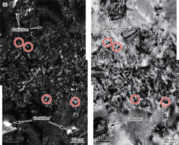
图8
弱束TEM明暗场下焊缝中峰值区域的位错环分布(850℃)
Fig.8
Weak-beam dark-field ( g /3 g ) TEM image (a) and bright-field TEM image (b) of the dislocation loops in the peak region of the weld metal at 850oC (The dislocation loops appear as white dots under the weak beam dark-field condition, and becomes black dots at the same position under the bright-field as shown in the red circles; the same in Fig.9)
图9
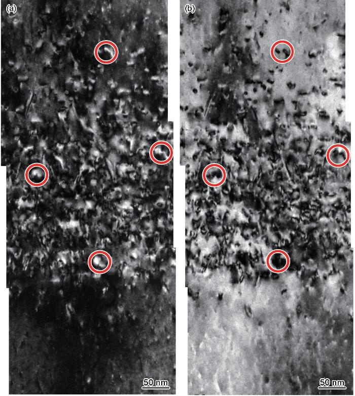
图9
弱束TEM明暗场下母材中的峰值区域位错环的分布(850℃)
Fig.9
Weak-beam dark-field ( g /3 g ) TEM image (a) and bright-field TEM image (b) of the dislocation loops in the peak region of the base metal at 850oC
2.3 辐照后焊缝,母材的纳米硬度
式中,H是实验得到的硬度;
图10

图10
辐照前后母材和焊缝的硬度随压入深度变化及
Fig.10
Nanohardness vs indentation depth (a, b) and H 2-1/ h curves (c, d) of the base metal (a, c) and weld metal (b, d) before and after irradiation
3 分析讨论
经相同条件辐照后,焊缝和母材中的He泡和位错环的演化以及力学性能均存在着差异。这是由焊缝和母材不同的本征微观结构所决定的。辐照前的焊缝中晶粒内部存在高密度的位错线以及分布不均匀的纳米碳化物,而母材晶粒内部仅有少量的位错线。辐照后,焊缝中的He泡集中分布在位错线和碳化物-基体界面上(图5b),甚至在辐照损伤峰值之后更深的位置上,也可以在碳化物-基体界面上观察到He泡。母材中的He泡和位错环分布在一起,构成环-泡复合体(图5d)。这个结果说明在850℃下,焊缝中碳化物-基体界面和位错线对He原子有着非常强的捕获能力,并且已经抑制了He泡在基体中的均匀形核。而在母材中,He泡的形核除了受到少量位错线的影响外,更多的则是自由均质形核,同时在长大过程中会与间隙位错环相互作用[13]。温度是影响He泡在碳化物-基体界面以及位错线等这些特殊结构形核的关键因素[14],随着温度的升高,这些缺陷阱捕获He原子的能力也会越强。在之前的650℃下氦离子辐照焊接接头的研究[20]中发现,焊缝中除了可以观察到He泡在位错线上分布外,基体中也分布着大量He泡。对比850℃下的结果,He泡基本分布在碳化物-基体界面和位错线上,说明更高温度下位错线对He泡的捕获力更强。同时在高温下,He泡在这些位置形成稳定的核所需的临界He原子浓度比合金基体中的更小[14]。因此在850℃下,更多的He原子能够被这些缺陷阱所捕获,抑制了基体中He泡的形核,从而导致焊缝中He泡数密度整体小于母材。
位错线、析出相-基体界面以及晶界是He原子的强捕获阱的理论已经得到科研人员验证[14,15,17],并在样品中也观察到了He泡在这些特殊位置的偏向分布。与本工作观察到的结果一样,他们也观测到碳化物-基体界面上He泡尺寸更小,即在碳化物-基体界面上是高密度弥散分布的小He泡。本工作统计结果显示,碳化物上He泡的尺寸为(3.03 ± 0.79) nm,其峰值位错线上分布的He泡平均尺寸为(4.70 ± 1.22) nm。这说明碳化物-基体界面对He原子具有强捕获力,但同时又会抑制He泡的长大。Ding等[28]使用第一性原理对低活化铁素体/马氏体(RAFM)钢中VC上的He泡和点缺陷进行了研究,结果表明,碳化物上的C空位非常容易形成,但是C空位在VC中的扩散较Fe基体中扩散慢得多,使得VC中C空位更加弥散分布。同时He更倾向于取代VC中C的位置,而不是Fe基体中Fe的位置,因此相较Fe基体,VC中存在的大量且分散的空位拥有更强的捕获He的能力,且He被捕获后又很难扩散,这也就意味着很难形成大尺寸的He泡。Ding等[28]指出在其他碳化物以及氧化物弥散强化(ODS)钢中的氧化物上也是类似的规律。因此,本工作推测GH3535焊缝中的M6C碳化物上也是因为其上弥散分布着大量C空位,吸收大量He原子,但又很难聚集长大,最终使得碳化物-基体界面上分布着高密度、小尺寸的He泡;同时推测正是因为这些可以容纳更多He原子的碳化物的存在,使得合金基体中He原子大量减少,也在一定程度上抑制了基体中He泡的形核,降低了焊缝中He泡的数密度。
焊缝中峰值处位错线上的He泡平均尺寸不仅比碳化物上He泡尺寸大,同时也比母材中的He泡尺寸大。这是因为焊缝中存在的大量位错线是He泡的快速扩散通道,能够促进He泡的长大,这与已有的研究[29]以及本课题组先前的结果[20]是一致的。从本工作He泡随辐照深度的分布上也可以看出,焊缝的峰值分布相较于母材向更深处移动了约100 nm,这也与高温下位错线对He原子的长程扩散传递有很大的关系。因为焊缝中有着大量的位错线,He原子进入后,在850℃下基本被这些强阱吸收,同时可以沿着位错线扩散,因此使得最终He泡分布的深度向更深处扩散了约100 nm。综上所述,基于焊缝中碳化物和位错线的存在,最终形成了较低密度、稍大尺寸的He泡,使得最终焊缝中整体的肿胀率(峰值区域0.32%)低于母材(峰值区域0.44%)。
对于辐照后焊缝和母材中位错环的演化差异,统计结果显示焊缝中的位错环相较母材而言数密度更小,尺寸也较小,如图8和9所示。焊缝中大量位错线作为一种偏压势阱,吸收间隙子的速率大于空位,因此会在一定程度降低周围基体中的间隙子浓度,抑制基体中位错环的形成。Li等[30]使用原位TEM也观察到在纯Mo中预先存在的位错线处辐照产生的缺陷形核率较其他区域明显低很多,并发现随着辐照剂量增加,位错线周围直至0.07 dpa也没有观察到位错环的生成,而其他区域在0.01 dpa时就可以明显观察到位错环的存在;同时还指出,预先存在的位错线及晶界是非常强的缺陷阱,可以吸收点缺陷。另外焊缝中存在的纳米碳化物界面作为同时捕获间隙子和空位的缺陷阱可以促进空位和间隙子在其上的复合[31],也导致其周围间隙子浓度减小,从而抑制了位错环的形成。基于此,焊缝中位错环的形成受到了抑制,使得最终数密度和尺寸均小于母材。在母材中可以观察到较大尺寸的位错环以及环-泡复合体的存在。这在先前的工作[13]中已进行过讨论,一方面在高温下,He原子-空位复合体形成会发射自间隙子到基体中,这些间隙子会促进位错环的形成,并附着在He-空位复合体上,形成环-泡复合体。另一方面高温下这些间隙团簇、He-空位团簇以及He-空位-自间隙子复合体的迁移合并也会促进环泡复合体的长大。当然He泡和位错环的相互作用受温度的影响比较大,研究[13]表明,对于GH3535合金,在850℃下,才观察到这种大尺寸的环-泡复合体。
表2 850℃下经2 × 10¹⁶ ions/cm2氦离子辐照后焊缝和母材的屈服强度增量与纳米硬度增量
Table 2
| Sample | Defect | Δσ MPa | Δσtotal MPa | Δ GPa | Δ GPa |
|---|---|---|---|---|---|
| GH3535 | Helium bubble | 310 | 580 | 1.74 | 1.84 |
| Dislocation loop | 490 | ||||
| Weld metal | Helium bubble | 240 | 342 | 1.02 | 1.21 |
| Dislocation loop | 243 |
最终计算结果也列于表2中。将计算后的硬度增量和本实验得到的纳米硬度增量进行对比,可见数据吻合得很好。这也就意味着辐照后样品的硬化是来源于辐照产生的He泡和位错环的钉扎作用。相同辐照条件焊缝中的He泡和位错环的平均数密度与尺寸均小于母材,这是造成辐照后焊缝样品的硬化程度(36%)低于母材(70%)的关键原因。因此尽管焊接过程中反复的高温热循环会使得焊接接头发生组织结构变化,但对于焊缝来说,在850℃辐照下,正是因为这些本征结构,如高密度位错线和纳米碳化物的存在,使得焊缝中产生更少的He泡以及位错环,从而使得焊缝的硬化程度以及肿胀率均低于母材。
4 结论
(1) 850℃下经2 × 10¹⁶ ions/cm2氦离子辐照后,焊缝中He泡呈现多面体形状,He泡的数密度((7.80 ± 0.97)× 1022 m-3)约为母材中的一半((1.68 ± 1.35) × 1023 m-3),尺寸((4.27 ± 1.13) nm)略大于母材((3.45 ± 0.93) nm)。位错环的数密度和尺寸均小于母材。其中焊缝中位错环平均尺寸为(7.33 ± 1.66) nm,数密度为(2.14 ± 0.31) × 1022 m-3。母材中位错环平均尺寸为(10.91 ± 4.40) nm,数密度为(5.86 ± 0.68) × 1022 m-3。根据He泡的数密度和尺寸计算的焊缝的肿胀率低于母材。
(2) 相较低温下,850℃下焊缝中的碳化物-基体界面和位错线对He原子的强捕获能力更明显,He泡基本分布在位错线和纳米碳化物-基体界面上。纳米碳化物-基体界面对He原子有着较强的捕获作用,且可以有效抑制He泡的长大,峰值区碳化物-基体界面上的He泡平均尺寸为(3.03 ± 0.79) nm。而其位错线的存在可以促进He泡的长大,其峰值位错线上的He泡平均尺寸为(4.70 ± 1.22) nm。
(3) 焊缝和母材辐照硬化是由He泡和位错环共同造成的,焊缝的硬化程度(36%)远小于母材的硬化度(70%),这是由于焊缝中高密度位错线和纳米碳化物的存在,有效吸收了更多的He原子和间隙子,既有效降低了He泡的密度,又抑制了位错环的形成和长大,使得焊缝中He泡平均数密度以及位错环的平均数密度和尺寸均低于母材。
参考文献
Structural materials challenges for advanced reactor systems
[J].
Microstructure and local strains in GH3535 alloy heat affected zone and their influence on the mechanical properties
[J].
Microstructure and mechanical properties of UNS N10003 alloy welded joints
[J].
Temperature dependence of nickel ion irradiation damage in GH3535 alloy weld metal
[J].
Study on microstructure change and hardening of 316L steel weld seam after helium ion irradiation
[J].
Structural materials for fission & fusion energy
[J].
Materials challenges in nuclear energy
[J].
An evaluation of the molten-salt reactor experiment Hastelloy N surveillance speciments—Fourth group
[R].
Effect of helium bubbles on irradiation hardening of additive manufacturing 316L stainless steel under high temperature He ions irradiation
[J].
On the irradiation tolerance of nano-grained Ni-Mo-Cr alloy: 1 MeV He+ irradiation experiment
[J].
Coalescence mechanism of helium bubble during tensile deformation revealed by in situ small-angle X-ray scattering
[J].
Temperature dependence of He bubble evolution in UNS N10003 alloys under He ion irradiation
[J].
The effects of irradiation temperature on helium bubble evolution in UNS N10003 alloys were studied using 500 keV He ion irradiation at a dose of 2 × 10¹⁶ ions/cm2 from 650 to 850 °C. As the irradiation temperature increased, the density of the helium bubbles decreased and their size increased. Polyhedral bubbles were observed at 850 °C, and the non-spherical shapes of these bubbles reduced their surface energy. The densities and mean diameters of the bubbles at 650–850 °C show Arrhenius behaviors with activation energies of 1.06 ± 0.17 and 0.35 ± 0.02 eV, respectively. The activation energies indicate that the He bubble evolution at temperatures ranging from 650 to 850 °C is not only controlled by He diffusion via a self-interstitial/He replacement mechanism but is also affected by the migration and coalescence of He clusters or bubbles via surface diffusion. Furthermore, bubble-loop complexes were observed at 750 and 850 °C. With the temperature increasing, the helium bubbles prompted the growth of dislocation loops, suggesting that the interaction between the helium bubbles and the dislocation loops is dependent on the irradiation temperature.
Helium accumulation in metals during irradiation-where do we stand?
[J].
Formation of bubbles in helium implanted 316L stainless steel at temperatures between 25 and 550oC
[J].
Helium trapping at dislocations, precipitates and grain boundaries
[J].
Bubble formation in helium-implanted nanostructured ferritic alloys at elevated temperatures
[J].
Helium entrapment in a nanostructured ferritic alloy
[J].
A potential candidate structural material for molten salt reactor: ODS nickel-based alloy
[J].The commercialisation of molten salts reactors (MSRs) is hindered by the lack of structural materials capable of withstanding the corrosive environment therein. To address this problem, we herein prepared 1 wt% Y2O3 dispersion-strengthened NiMo-based alloys using powder metallurgy and evaluated their potential as structural materials for MSRs based on their mechanical properties, He swelling behaviour, and molten salt corrosion resistance. In view of the strengthening provided by homogenously dispersed Y2O3 particles, all NiMo-Y2O3 samples exhibited ultimate tensile strengths and yield strengths exceeding those of the Hastelloy N alloy, a state-of-the-art structural material for MSRs. Moreover, the volume fraction of He bubbles in the NiMo-Y2O3 samples (∼0.3%) was lower than that in the Hastelloy N alloy (0.58%), which showed that the introduction of Y2O3 nanoparticles effectively inhibited He swelling. All NiMo-Y2O3 samples showed excellent resistance to molten salt corrosion (as reflected by the absence of obvious holes therein), thus holding great promise for the development of irradiation- and molten salt corrosion-resistant structural materials for high-temperature MSRs.
Effect of helium bubbles on the irradiation hardening of GH3535 welded joints at 650oC
[J].
Irradiation damage in GH3535 alloy under He ion irradiation at high temperature
[J].
高温He离子辐照GH3535合金的损伤效应
[J].
The stopping and range of ions in matter
[A].
A comparison study of void swelling in additively manufactured and cold-worked 316L stainless steels under ion irradiation
[J].
Evolution of fine-scale defects in stainless steels neutron-irradiated at 275oC
[J].
Indentation size effects in crystalline materials: A law for strain gradient plasticity
[J].
A new approach to evaluate irradiation hardening of ion-irradiated ferritic alloys by nano-indentation techniques
[J].
First-principles investigations of intrinsic point defects and helium impurities in vanadium monocarbide
[J].
In-situ TEM observations of helium bubble interactions with dislocations
[J].
The evolution of dislocation loop and its interaction with pre-existing dislocation in He+-irradiated molybdenum: In-situ TEM observation and molecular dynamics simulation
[J].
Effects of carbide precipitate on the mechanical properties and irradiation behavior of the low activation martensitic steel
[J].
The evolution of mechanical property change in irradiated austenitic stainless steels
[J].
Dislocation movement through random arrays of obstacles
[J].A computer program that determines the stress required to move a dislocation through an array of obstacles distributed at random on a slip plane has been written. This program has been used to measure the critical shear stress of random arrays of (a) obstacles of various equal strengths, (b) obstacles with two differing strengths, (c) obstacles with a square spectrum of strengths, and (d) circular prismatic loops lying on {110} planes in a face-centered cubic crystal.
Microstructure evolution in austenitic Fe-Cr-Ni alloys irradiated with rotons: Comparison with neutron-irradiated microstructures
[J].
