



传统材料力学性能检测方法需要在部件中取标准样品,通常会对部件造成破坏[1],同时对于薄壁结构部件,特别是对于现役关键部件如航空发动机涡轮叶片,往往面临取样困难、几何尺寸受限等问题,导致难以标准取样进行性能分析,所以传统材料力学性能检测方法在一些工程实际应用中存在局限性。相比之下,压痕测试技术对试样尺寸的限制极少甚至可以实现无取样检测[2],并具有适用范围广、可测力学参数种类丰富等优势[3,4],展现出了广阔的应用前景。工程应用上也希望能够在最小化结构损伤的前提下获取精确的材料力学性能数据,这一需求极大地推动了压痕技术的发展与完善。工程实践表明,压痕技术能够以较高的正确率实现焊点的在线质量检测[5],并且弹性模量的测量结果可保持与传统方法±7%以内的偏差[6]。这一特性使其成为现代工程力学性能评估的重要发展方向,特别是在航空航天关键部件完整性监测、能源装备服役状态诊断以及结构剩余寿命预测等工程实践领域具有突出的应用潜力。
虽然压痕技术通过相对简单的实验操作并结合有限元模拟即可获取包括硬度、弹性模量、屈服强度及蠕变应力指数等在内的多项力学性能指标[7~12],但在实际应用中对测试设备精度要求高,需要具备高分辨率的载荷-位移实时监测能力,易受测试环境扰动(温度波动、地表震动等)和试样制备质量因素(表面粗糙度、试样厚度等)等影响,有限元模拟中参数的设定(网格密度、摩擦系数等)也会对结果的准确性有较大的影响[13,14]。Intarit等[15]研究了平头圆柱形压头下的摩擦压痕问题,发现接触力和表面位移的轮廓对压头与基底之间的Coulomb摩擦系数(μ)有很强的依赖性,并且随着μ的增加,黏附区产生的法向接触力和径向牵引力会变得更低。Du等[16]研究结果表明,摩擦接触在球形压痕的蠕变行为中起着至关重要的作用,在没有摩擦的情况下,72S钢的蠕变行为可以偏离多达310%,纯Ni合金的蠕变行为可以偏离多达28%。Lee等[17]的研究结果同样表明摩擦系数会对仿真结果带来影响。此外,Yang[18]在研究刚性圆柱压头在基底弹性层上的压痕问题时,考虑了样品厚度的影响,结果表明,当接触半径与试样厚度之比大于1时,试样厚度尤其是薄膜试样的厚度是不可忽略的。瞿力铮等[19]采用有限元方法研究6061铝合金球压痕时发现,试样厚度小于4倍压头半径时,应力波反射会导致松弛曲线出现异常波动,建议临界厚度取压头半径的4倍。Pan等[20]研究了TiNi薄膜在两种压头下的纳米压痕响应差异,发现球形压痕呈现100%深度恢复率,以弹性变形为主导并伴随不完全相变,而Berkovich压痕因几何尖锐导致应力集中,弹性恢复率仅为68%且相变特征被塑性变形掩盖。Li等[21]研究表明,球形压头半径对单晶B3-GaN的力学性能有影响,随着压头半径的增加,原子位移和Mises应力的大小和分布范围以及从弹性变形过渡到塑性变形的临界载荷逐渐增加,硬度和剪切应变逐渐降低,为纳米压痕实验中压头尺寸的合理选择提供了依据。这些研究成果共同为压痕测试技术的标准化应用提供了理论支撑和实践指导。
虽然压痕测试技术已被广泛应用于材料力学性能表征领域,但仍需深入研究实验条件对压痕松弛行为的影响。本工作以Sanicro25奥氏体耐热钢作为模型材料,通过压痕有限元模拟分析试样网格密度、试样厚度与压入深度之比(厚深比)、摩擦系数以及压头几何形状等因素对压痕力学行为测试结果的影响。
1 实验方法
图1
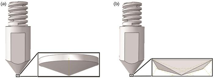
图1
圆锥形和四棱锥形压头的示意图
Fig.1
Schematics of conical (a) and quadrangular pyramid (b) indenters
采用自主研制的DZY.2000电子式蠕变试验机开展压痕松弛蠕变实验。高温环境由三区独立控温电阻炉(轴向长度500 mm)提供,各温区通过S型热电偶实现闭环控制,通过两组独立调节的加热体实现轴向300 mm范围内温度场的均匀分布,结合缓冲温区的热耦合设计有效抑制了边界热传导引起的非稳态温度波动(波动控制在±1 ℃以内);力学加载单元集成伺服电动缸驱动系统(最大载荷2 kN)和滚珠丝杠传动机构,通过模块化接口实现恒载荷/恒应变/恒位移多模式加载功能;压头固定在中心控制位移支架上,正对载物台放置试样,确保试样位于压头下方的平台中心。实验在充N2气氛的高温炉中进行,以抑制试样氧化。升温前持续通入N2,保温前5~10 min停止通气,避免气流扰动引起温度变化。将高温炉加热至实验温度(750 ℃),待试样表面温度达到预设值后,保温2 h使炉内温度分布均匀。随后施加20 N初始载荷,确保压头与试样表面稳定接触。以0.5 μm/s速率将压头压入至0.1 mm深度后保持压深恒定,通过高精度位移传感器(精度0.1 μm)实时监测载荷变化,并自动记录载荷、时间、位移及温度数据。试验机负载能力为0~5000 N,数据由计算机同步采集。最后以0.5 μm/s相同速率卸载,完成单次压痕松弛实验。
本工作在有限元模拟中基于两种压头的轴对称特性,采用1/4对称模型进行计算,采用10节点二次四面体单元(C3D10)对试件进行建模。为了准确得到接触区域的应力集中效应并兼顾计算效率,采用非均匀网格划分,在压头尖端及接触区域实施局部网格加密(最小单元尺寸0.005 mm),网格尺寸沿远离尖端方向呈梯度递增,直至外围区域达到最大单元尺寸(0.3 mm),试件三维剖面和表面的有限元计算网格如图2所示。模型底部约束完全固定,侧面设置轴对称约束。
图2

图2
试件三维剖面和表面的有限元计算网格
Fig.2
Finite element calculation mesh for the three-dimensional cross-section (a) and surface (b) of the specimen (Insets are corresponding partially enlarged views)
2 实验结果
式中,
图3
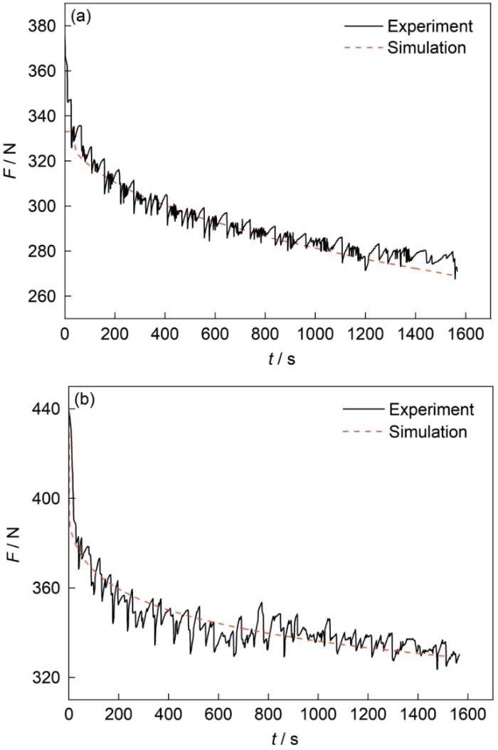
图3
Sanicro25钢在圆锥形压头和四棱锥形压头在最大压痕深度0.1 mm下的压痕模拟结果与实验结果对比
Fig.3
Comparison of simulation and experimental results for Sanicro25 steel under conical (a) and quadrangular pyramid (b) indenters with a depth of 0.1 mm (F—maximum force, t—compression head pressing time)
表1 Sanicro25钢在不同压头作用下的实验与模拟结果对比
Table 1
| Indenter shape | Force at 1500 s / N | Error % | Curvature difference (STDEV) | |
|---|---|---|---|---|
| Experiment | Simulation | |||
| Conical | 276.36 | 270.28 | 2.20 | 4.55 |
| Quadrangular pyramid | 335.21 | 329.57 | 1.68 | 6.90 |
综合误差与标准差指标可知,圆锥形压头的模拟结果具有更高的全局一致性,其拟合优度优于四棱锥形压头,该结论通过图3a中实验曲线与模拟曲线的紧密贴合得到进一步验证。
3 分析与讨论
3.1 网格密度依赖性分析
网格密度是影响模拟结果的一个重要因素[25,26]。为了研究网格密度依赖性,同等程度地改变距压痕中心0.05 mm范围内3个方向的网格密度,共采用了11种网格尺寸,分别为0.004、0.008、0.012、0.015、0.020、0.025、0.030、0.035、0.040、0.045、0.050。在所有模拟工况中保持0.1 mm的最大压痕深度以确保结果的可比性。图4给出了被测试样模型网格密度对松弛曲线的影响。可以看出,网格密度对时间-载荷曲线的影响可以忽略不计,不同网格划分对模拟结果的精确性影响在可接受范围内。因此,为兼顾计算效率与结果精度,本工作选取最小网格长度位于尺寸序列中间值的0.025 mm建立有限元模型,以确保模拟的可靠性。
图4
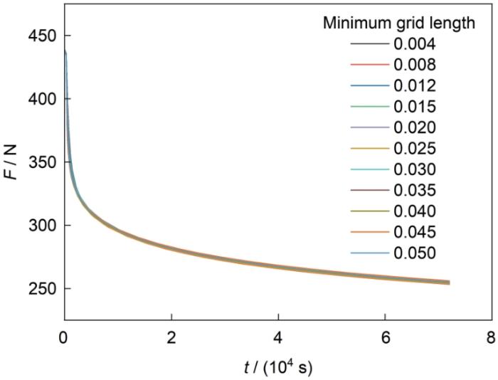
图4
试样模型网格密度对松弛曲线的影响
Fig.4
Effect of mesh density of sample model on relaxation curve
3.2 厚深比对压痕松弛行为的影响
在压痕松弛过程中,试样厚度和压入深度作为关键参数显著影响测试结果的准确性,当试样厚度过薄且压入深度较大时,试验台基体效应的干扰会导致试样受力状态发生变化,从而引起实验数据的系统性偏差;反之若试样过厚,则难以充分发挥压痕实验所需测试材料量少的优势[13]。ISO 14577-1:2015标准建议,试样厚度应至少为压痕深度的10倍(厚深比≥ 10),以避免基底效应对测试结果的影响,但是该范围仅为一个基础性的参考值,因此合理选择试样厚度与压入深度的匹配关系,对于确保实验结果的可靠性及保持该方法的技术优势具有重要意义。模拟中采用0.1 mm的最大压痕深度,通过改变试样厚度来建立不同的厚深比关系,选取0.25、1、2、2.4、3、4、6、8和16 mm共9组试样厚度,对应的厚深比分别为2.5、10、20、24、30、40、60、80和160。
图5

图5
厚深比对松弛曲线和最大力的影响
Fig.5
Effects of thickness-to-depth ratio on relaxation curve (a) and maximum force (b)
3.3 摩擦系数对压痕松弛行为的影响
在压痕有限元模拟中,为降低计算复杂度和提高计算效率,通常假设压头与试样接触界面为理想无摩擦状态,但在实际接触过程中摩擦效应是客观存在的,且会对压痕周围材料的堆积形貌产生一定影响。为系统研究摩擦系数对压痕松弛响应的影响规律,本工作在有限元模型中引入界面摩擦因素,设置0、0.10、0.15、0.20和0.30等5组不同摩擦系数进行对比分析。不同摩擦系数下松弛曲线的模拟结果如图6所示。可见,摩擦系数对最大力影响较大,其在0~0.30范围内变化时最大力的相对偏差最大可达18.41%。
图6

图7

图7
不同摩擦系数下根据红色路径提取的压痕表面轮廓
Fig.7
From the red path (a) on the specimen surface, the indentation surface profile diagrams (b) extracted under different friction coefficients (Inset in Fig.7b is the locally enlarged diagram)
3.4 压头几何形状对压痕松弛行为的影响
3.4.1 压痕应力分布特征
图8

图8
圆锥形和四棱锥形压头在最大压痕深度(0.1 mm)下试样表面压痕Mises应力分布
Fig.8
Mises stress (S) distributions of indentation on specimen surface under maximum indentation (0.1 mm) depth with conical (a) and quadrangular pyramid (b) indenters
图9
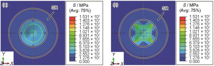
图9
圆锥形和四棱锥形压头完全卸载后试样表面压痕Mises应力分布
Fig.9
Mises stress distributions of indentation on specimen surface after conical (a) and quadrangular pyramid (b) indenters are completely unloaded (SR—stress ring)
两种压头形状下的应力场呈现以下共同规律:在最大压痕深度时,等效应力极值均集中于压头尖端与材料接触的微区,表现出典型的接触应力集中现象[27];载荷卸载后的应力场均呈圆形,应力场的分布面积明显增大(面积较加载状态增大58.46%~76.70%),并且所有压头工况下均观测到明显的残余应力环(stress ring),证实了材料在蠕变过程中发生了塑性应变。
但是,不同形状压头作用下应力分布的差异更为显著:在相同压痕深度和蠕变时间下,压痕应力的大小因压头形状的不同而变化。圆锥和四棱锥形状压头作用下的最大等效应力依次升高,分别为1345.00和1728.00 MPa;载荷卸载后,最大等效应力明显降低,分别为1036.00和1531.00 MPa。圆锥形压头的应力释放率为22.97%,大于四棱锥形的11.40%,这种差异主要源于不同压头几何形状在变形过程中产生的约束效应差异,圆锥形压头由于几何约束较小而表现出更显著的应力释放特性,四棱锥形压头由于棱边应力集中则以塑性应变为主。此外,最大压痕深度时,圆锥与四棱锥形状压头作用下的压痕Mises应力云图分别呈圆形和正方形;完全卸载后,圆锥形、四棱锥形压头的残余应力环分别在86.32~172.60和127.60~255.20 MPa范围。
图10
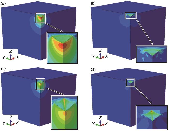
图10
圆锥形压头和四棱锥形压头作用下Sanicro25钢在压痕最大深度和完全卸载后的剖面Mises应力分布云图(最大压深0.1 mm)
Fig.10
Profile Mises stress distribution nephograms and partially enlarged views (insets) of Sanicro25 steel at maximum inden-tation depth (a, c) and after unloading (b, d) under two shapes of indenters (The maximum penetration depth is 0.1 mm)
(a, b) conical indenter (c, d) quadrangular pyramid indenter
图11

图11
圆锥形压头和四棱锥形压头作用下Sanicro25钢在压头完全卸载后沿不同路径的残余应力分布曲线
Fig.11
After complete unloading of the conical indenter (a, b) and quadrangular pyramidal indenter (c, d), residual stress distribution curves (b, d) of Sanicro25 steel along different paths (a, c) on the specimen are shown (Insets in Figs.11b and d are the locally enlarged diagrams)
从整体趋势上看,最大残余应力位于压痕中心区域。其中,圆锥形和四棱锥形压头作用下路径1上的残余应力沿Z轴方向均呈现出“先降低-再升高-再降低”的变化规律,残余应力在压痕中心区的正下方发生了应力集中现象,应力分别在59.59~118.42和64.23~90.88 MPa之间。路径2上的残余应力分布较为均匀,分别在17.82~87.95和18.98~81.14 MPa之间,但残余应力在压痕变形区的“边界”均发生不同程度的应力集中,应力分别在116.27~197.62和115.15~238.81 MPa之间。四棱锥形压头作用下路径3上的残余应力在压痕对角线区域以及尖角区域发生了较大程度的应力集中,应力范围为444.35~1456.28 MPa。
3.4.2 压痕等效应变分布
当前增量步的等效塑性应变(PEEQ)是描述材料塑性变形程度的标量,定义为:
式中,
等效蠕变应变(CEEQ)是等效蠕变应变率(
式中,
图12
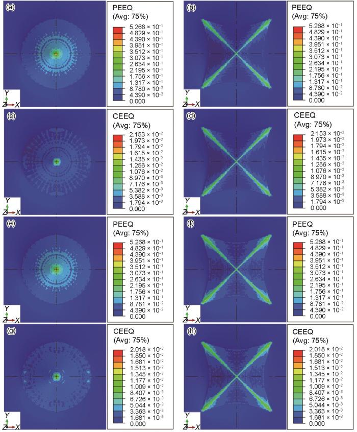
图12
圆锥形压头和四棱锥形压头作用下Sanicro25钢在压痕最大深度(0.1 mm)和完全卸载后表面的等效塑性应变和等效蠕变应变云图
Fig.12
Equivalent plastic strain (PEEQ) (a, b, e, f) and equivalent creep strain (CEEQ) (c, d, g, h) nephograms of Sanicro25 steel under two shapes of indenters at the maximum indentation depth (0.1 mm) (a-d) and after complete unloading (e-h) on the surface
其次,圆锥形状压头作用下塑性应变和蠕变应变主要发生在压痕中心区域,取值范围分别为0.482~0.526和0.013~0.015;四棱锥形状压头作用下塑性应变和蠕变应变主要发生在压痕对角线区域,取值范围分别为0.483~0.527和0.020~0.022,4个斜面区域的塑性应变和蠕变应变则维持在较低水平,取值范围分别为0~0.044和0~0.002,这表明压痕斜面区域的变形受压头的影响较压痕对角线小。在远离压痕变形区的其他区域,Sanicro25钢未发生明显的塑性变形和蠕变变形。
图13为Sanicro25钢分别在圆锥形和四棱锥形压头卸载后沿不同路径的等效应变分布曲线。结果表明,不同压头形状作用下,在被测材料的边缘,等效塑性应变和等效蠕变应变均近似为0,即可认为远离压痕的区域不发生变形。圆锥形压头作用下,在远离压痕变形中心区的过程中,等效塑性应变随之降低,而四棱锥形压头作用下的等效塑性应变在棱边区域集中;圆锥形压头作用下的最大等效蠕变应变发生在压痕变形中心区的正下方,而四棱锥形压头作用下的最大等效蠕变应变则发生在棱边尖端区域。
图13
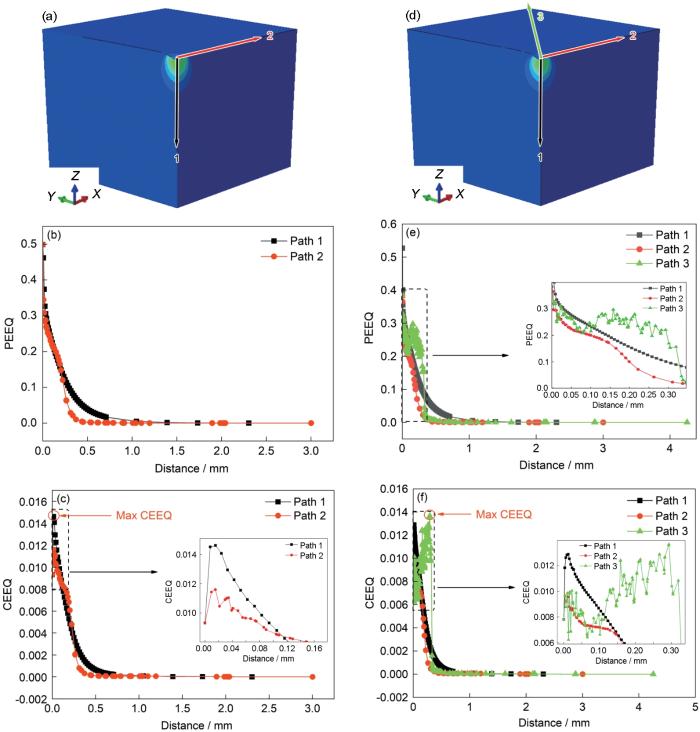
图13
Sanicro25钢在两种形状压头完全卸载后沿不同路径的等效塑性应变和等效蠕变应变分布曲线
Fig.13
Along different paths (a, d) on the specimen of Sanicro25 steel after unloading by two shapes of indenters, PEEQ (b, e) and CEEQ (c, f) distribution curves are shown (Insets in Figs.13c, e, and f are the locally enlarged diagrams)
(a-c) conical indenter (d-f) quadrangular pyramid indenter
3.4.3 不同形状压头下的松弛曲线
图14
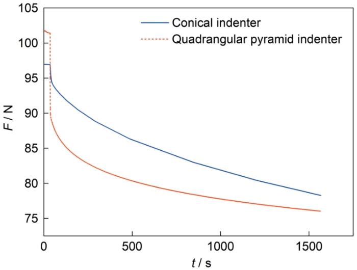
图14
两种压头在0.1 mm最大压深下的松弛曲线
Fig.14
Relaxation curves of two indenters at 0.1 mm maximum pressure depth
由前文应力分布结果可知,四棱锥棱边处存在应力集中,这导致四棱锥压头作用下的初始松弛速率快于圆锥压头,并且为了达到相同的位移,圆锥压头施加的力应大于四棱锥压头施加的力。
4 结论
(1) 在750 ℃、最大压痕深度为0.1 mm条件下,被测试样模型的最小网格长度在0.004~0.050范围内变化对压痕松弛曲线影响很小,距压痕中心0.05 mm范围内选择最小网格长度为0.025的有限元模型是可靠的。
(2) 摩擦系数对测试结果有明显影响,当其值从0增加到0.30时,对应的最大力增大了18.41%;同时会明显改变压痕表面形貌,随着摩擦系数的增大,材料堆积高度递减,但当摩擦系数超过0.15后,堆积高度的变化幅度显著减小,不同摩擦系数下的结果趋于一致。
(3) 当厚深比较小(< 20)时,由于试样厚度不足引起的边界效应会导致模拟结果产生显著偏差;当该比值≥ 20时,松弛曲线基本一致,进一步增大厚深比不会引起曲线的显著变化。在实验中应将厚深比控制在20以上以确保数据的可靠性。
(4) 压头几何形状显著影响应力场的分布特征。圆锥形压头产生典型的轴对称应力场;四棱锥形压头由于棱边效应导致应力集中现象明显,会加速初始松弛速率。对于给定尺寸的两种压头,在相同压痕深度作用下,四棱锥压头会产生比圆锥压头更大的等效蠕变应变。
参考文献
Advances and trends of testing technology of mechanical properties of materials
[J].
材料力学性能测试技术的进展与趋势
[J].
The application of stress-strain microscopic probe technology in pipeline safety and inspection
[A].
应力应变显微探针技术在管道安全与检测中的应用
[A].
Review of instrumented indentation
[J].Instrumented indentation, also known as depth-sensing indentation or nanoindentation, is increasingly being used to probe the mechanical response of materials from metals and ceramics to polymeric and biological materials. The additional levels of control, sensitivity, and data acquisition offered by instrumented indentation systems have resulted in numerous advances in materials science, particularly regarding fundamental mechanisms of mechanical behavior at micrometer and even sub-micrometer length scales. Continued improvements of instrumented indentation testing towards absolute quantification of a wide range of material properties and behavior will require advances in instrument calibration, measurement protocols, and analysis tools and techniques. In this paper, an overview of instrumented indentation is given with regard to current instrument technology and analysis methods. Research efforts at the National Institute of Standards and Technology (NIST) aimed at improving the related measurement science are discussed.
An improved technique for determining hardness and elastic modulus using load and displacement sensing indentation experiments
[J].The indentation load-displacement behavior of six materials tested with a Berkovich indenter has been carefully documented to establish an improved method for determining hardness and elastic modulus from indentation load-displacement data. The materials included fused silica, soda–lime glass, and single crystals of aluminum, tungsten, quartz, and sapphire. It is shown that the load–displacement curves during unloading in these materials are not linear, even in the initial stages, thereby suggesting that the flat punch approximation used so often in the analysis of unloading data is not entirely adequate. An analysis technique is presented that accounts for the curvature in the unloading data and provides a physically justifiable procedure for determining the depth which should be used in conjunction with the indenter shape function to establish the contact area at peak load. The hardnesses and elastic moduli of the six materials are computed using the analysis procedure and compared with values determined by independent means to assess the accuracy of the method. The results show that with good technique, moduli can be measured to within 5%.
On-line weld quality inspection based on weld indentation by using servo gun
[J].
基于焊点压痕的伺服焊枪点焊质量在线检测方法
[J].
Measurement of hardness and elastic modulus by instrumented indentation: Advances in understanding and refinements to methodology
[J].The method we introduced in 1992 for measuring hardness and elastic modulus by instrumented indentation techniques has widely been adopted and used in the characterization of small-scale mechanical behavior. Since its original development, the method has undergone numerous refinements and changes brought about by improvements to testing equipment and techniques as well as from advances in our understanding of the mechanics of elastic–plastic contact. Here, we review our current understanding of the mechanics governing elastic–plastic indentation as they pertain to load and depth-sensing indentation testing of monolithic materials and provide an update of how we now implement the method to make the most accurate mechanical property measurements. The limitations of the method are also discussed.
Experimental investigation on the effect of indenter shape on indentation and scratching behaviour of polymer materials
[J].
压头形状对高分子材料压痕和刮擦行为影响的实验研究
[J].
Hardening index and elastic modulus calculation method of material based on indentation test
[J].
基于压入试验的材料硬化指数及弹性模量计算方法
[J].
FEA of evaluating material yield strength and strain hardening exponent using a spherical indentation
[J].

Dimensional analysis was constructed to derive the dimensionless functions of a spherical indenter with 1 mm in diameter. The function can be used to extract the yield strength and strain hardening exponent of metal materials by means of finite element analysis. The fitting functions used to analyze materials yield strength and strain hardening exponent within the yield strains ranging from 0.00769 to 0.04 were obtained by numerical simulation. It has been validated that the prediction accuracy is enhanced and the average errors of the yield strength and strain hardening exponent are 1.6% and 12.6%, respectively.
球形压痕法评价材料屈服强度和应变硬化指数的有限元分析
[J].
On determination of elastic modulus and indentation hardness by instrumented spherical indentation: Influence of surface roughness and correction method
[J].
Determination of creep parameters from indentation creep experiments
[J].
由压痕蠕变试验确定材料的蠕变性能参数
[J].
Effect of temperature and strain rate on indentation size effect at shallow indentation depths
[J].
The influence of nanoindentation measurement factors on the test results of the mechanical behavior of IN718
[J].
纳米压痕测量因素对IN718力学行为测试结果的影响
[J].
Nanoindentation. Mechanical engineering series
[J].
Influence of frictional contact on indentation of elastic layer under surface energy effects
[J].
Using spherical indentation to determine creep behavior with considering empirical friction coefficient
[J].
A study on robust indentation techniques to evaluate elastic-plastic properties of metals
[J].
Thickness effect on the indentation of an elastic layer
[J].
Finite element simulation of tensile properties of power law hardening metal materials evaluated by continuous ball indentation technique
[J].The continuous ball indentation tests of typical power hardening metal material 6061 aluminum alloy were simulated using ABAQUS software by two- and three-dimensional modeling method. The indentation load-depth curves were obtained and verified by ball indentation experiments. The tensile property parameters by different methods were calculated based on the indentation load-depth curves, and compared with results from uniaxial tensile tests. The effect of sample thickness and distance between adjacent ball indenters on calculated tensile properties were analyzed. The results show that the indentation load-depth curve obtained by the three-dimensional modeling method was more consistent with the ball indentation experiment results. The representative stress and representative strain data obtained by three-dimensional modeling method was more consistent with the stress-strain curve acquired by tensile tests; the relative errors between calculated tensile strength, yield strength and experimental values were no more than 1%, indicating that the method could accurately characterize the tensile properties of test alloy. The critical sample thickness and critical distance bweeen adjacent ball indenters affecting the tensile properties were both 4 times of indenter radius.
连续球压痕法表征幂硬化金属材料拉伸性能的有限元模拟
[J].应用ABAQUS软件,采用二维和三维建模方法对典型幂硬化金属材料6061铝合金的连续球压痕试验进行了模拟,得到了压痕载荷-深度曲线,并进行了压痕试验验证;基于压痕载荷-深度曲线计算得到不同方法下的拉伸性能参数,并与单轴拉伸试验结果进行对比,分析了试样厚度、相邻球压头距离等压痕试验参数对拉伸性能计算结果的影响。结果表明:采用三维建模方法得到的压痕载荷-深度曲线与球压痕试验得到的更吻合;由三维建模方法得到的表征应力、表征应变数据与拉伸试验得到的应力-应变曲线更吻合,抗拉强度和屈服强度计算值与试验值的相对误差均不超过1%,说明该方法能够准确地表征试验合金的拉伸性能;影响拉伸性能的临界试样厚度和临界相邻和压头距离均为压头半径的4倍。
Different mechanical response of Ti-Ni film induced by the shape of indenter during nanoindentation
[J].
Effect of indenter radius on mechanical properties of B3-GaN in nanoindentation based on molecular dynamics
[J].
Indentation of elastic solids with a rigid Vickers pyramidal indenter
[J].
Dislocation creep modelling of Sanicro 25 based on microstructural evolution and particle hardening mechanism
[J].
Hot deformation behavior of Sanicro25 steel
[J].
Sanicro25钢热变形行为的研究
[J].
Effect of geometry angle on mechanical properties of Inconel 718 subsurface characterized by nanoindentation
[J].
纳米压痕几何角度对Inconel 718亚表面力学性能的影响
[J].
A study on the landform evolution of Danxia hillslope using numerical simulation
[J].
利用数值模拟方法研究宏观丹霞地貌坡地的演化过程
[J].
Two-stage SPS sintering preparation of ultrafine-grained Sialon-based ceramics and study on the microstructure and properties
[D].
超细晶Sialon基陶瓷两段式SPS烧结制备及组织性能研究
[D].


