



在航空发动机叶片失效案例中,疲劳失效占比高达71%,是第一失效形式[7]。叶片在高温、高压、高转速条件下长期服役的过程中承受巨大离心载荷,一旦出现长裂纹极易发生瞬时断裂。因此,疲劳小裂纹的萌生和扩展阶段是决定叶片服役寿命的关键阶段,其持续时间占总疲劳寿命的80%以上[8,9]。疲劳小裂纹是指尺寸小于材料显微结构单元,能够在疲劳裂纹扩展门槛值(ΔKth)以下扩展,且在相同应力强度因子范围(ΔK)以下扩展速率高于长裂纹的裂纹[10]。在TiAl合金中,小裂纹扩展速率比长裂纹高出几个数量级,且其扩展行为受晶界、夹杂物等微观结构特征的显著影响。在Ti-47Al-2Nb-2Cr-0.2B合金(原子分数,%,下同)中,当ΔK为6 MPa·m1/2时,长裂纹扩展速率约为10-10 m/cyc,小裂纹扩展速率为10-8~10-9 m/cyc[11]。因此,疲劳小裂纹的萌生和扩展阶段决定了叶片的安全寿命,仅基于长裂纹扩展理论进行寿命评估,可能会导致预测寿命高于实际寿命。
本文围绕TiAl合金疲劳小裂纹问题,阐述了疲劳小裂纹的基本定义,系统总结了其典型特征,重点归纳了TiAl合金中疲劳小裂纹的萌生位置及主导因素,分析了界面对小裂纹扩展行为的影响,并探讨了小裂纹的扩展规律。最后,基于TiAl合金疲劳小裂纹行为,总结了可用于构建TiAl合金统一疲劳寿命预测的扩展模型。
1 疲劳小裂纹的定义及其特点
图1
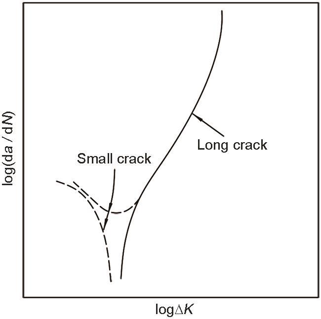
根据当前疲劳小裂纹的研究进展,可归纳出材料学意义上的小裂纹和广义小裂纹两个概念,二者在定义和适用范围上存在显著差异。
材料学意义上的小裂纹是一个机理驱动、内涵严谨的概念,特指尺寸微小而力学行为显著偏离经典长裂纹理论的裂纹。其定义并非基于绝对的物理长度,而是裂纹尺寸与材料内在特征尺度的对比:当裂纹长度小于晶粒尺寸、第二相尺寸等微观结构尺度时,其扩展会受到晶界、夹杂物的强烈影响[17],表现出随机性和不连续性;当裂纹尺寸小于裂纹尖端塑性区时,基于小范围屈服假设的传统断裂力学框架便会失效,需要对线弹性断裂力学模型进行修正或者采用弹塑性断裂力学模型进行分析。因此,这类小裂纹(常等同于“短裂纹”)扩展更快,且行为难以预测,通常认为材料学意义上的小裂纹为疲劳小裂纹的准确定义。疲劳小裂纹的具体尺寸随特定材料和载荷环境的不同而存在差异。在典型钢铁材料中,小裂纹的长度小于0.1 mm[18,19],而长裂纹的长度在1~20 mm之间;变形TiAl合金中小裂纹尺寸与钢铁材料相同,均小于0.1 mm[20]。此外,疲劳小裂纹的尺寸受应力比(R)的影响,对于片层TiAl合金,当R = 0.3时,其疲劳小裂纹尺寸小于0.2 mm;当R = 0.5时,疲劳小裂纹尺寸小于0.5 mm[21],随着R增大,小裂纹临界尺寸增大。
相对地,广义小裂纹是一个基于观测的、更为宽泛的工程统称。主要从检测、评价和工程维护的角度出发,泛指所有在几何尺寸上很小的裂纹,其长度通常在1 mm以下。这个定义的核心是绝对的工程尺寸,而非深入探究其物理本质。因此,广义小裂纹的范畴不仅包括前述材料学意义上的小裂纹,也涵盖了尺寸较小但跨越多个晶粒、扩展行为趋于稳定且可被传统断裂学理论近似描述的裂纹。针对广义小裂纹,依据其裂纹扩展行为和主导机制,主要有两种分类体系。一部分学者将其划分为三个阶段:微观小裂纹、物理小裂纹及结构小裂纹[22];另一部分学者则将其细分为四种类型:微观小裂纹、力学小裂纹、物理小裂纹和化学小裂纹[23~26]。微观小裂纹的尺寸与材料显微结构单元相当,其裂纹扩展行为受到晶界等微观结构的显著影响,在该阶段连续介质力学不再适用。微观小裂纹的扩展路径曲折且速率多变,通常取决于裂纹尖端的微观结构特征。力学小裂纹的裂纹尺寸小于裂纹尖端塑性区尺寸,小范围屈服条件不再适用,需要对线弹性断裂力学模型进行修正或者采用弹塑性断裂力学模型。当裂纹扩展至几个晶粒尺寸长度后,微观结构的影响消失,该阶段裂纹被认为是物理小裂纹,其裂纹尺寸通常小于1 mm,但大于微观组织的特征尺寸或者局部塑性区尺寸[26~28]。在环境因素的影响下,疲劳小裂纹扩展速率加快,此条件下裂纹被称作化学小裂纹。
本文从材料学角度和广义角度分别给出了疲劳小裂纹的定义。值得注意的是,小裂纹与短裂纹的含义并不相同。根据ASTM E1823标准[29],与微观结构尺度、连续介质力学尺度或物理尺寸尺度相比,当裂纹的长度(通常是贯穿裂纹的长度)很小时,定义为短裂纹;当裂纹的长度和深度都很小时,定义为小裂纹。尽管定义上存在差别,但鉴于两者规律相似,且在许多研究中没有严格区分,因此本文将小裂纹和短裂纹统称为“小裂纹”。
2 TiAl合金疲劳小裂纹的萌生和扩展机理
2.1 疲劳小裂纹的萌生位置
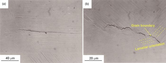
疲劳小裂纹通常在TiAl合金表面萌生。焦泽辉等[20]研究了变形TiAl合金中疲劳小裂纹的扩展行为,发现小裂纹在ΔK小于ΔKth时依然能够扩展,并且扩展速率高于长裂纹。在高循环应力下,变形TiAl合金表面的加工刻痕是小裂纹萌生的主要位置之一,小裂纹在扩展过程中受片层取向的影响,发生偏折并在偏折处合并[20]。Chan和Shih[33]研究了Ti-47Al-2Nb-2Cr-0.2B合金的疲劳行为,发现全片层组织的疲劳小裂纹在表面滑移带和晶界处萌生,如图2[33]所示。全片层组织的疲劳小裂纹并非随机萌生于表面滑移带或晶界,而是集中在表面滑移带累积交叉形成的应力集中区域,或是一些片层相界面、三叉晶界等特殊区域。
图2
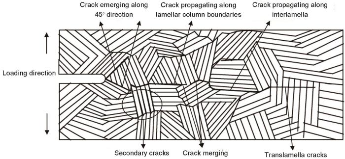
此外,疲劳小裂纹也可在TiAl合金内部萌生。Wessel等[34]研究了Ti-43Al-4Nb-1Mo-0.1B合金中的小裂纹扩展行为,确定了小裂纹萌生和扩展的三个阶段:裂纹在片层团内部萌生,然后扩展至临近晶粒,最后扩展为满足线弹性断裂力学模型的长裂纹。Edwards[35]发现,TiAl合金中疲劳小裂纹更易在软取向片层团(片层团与应力方向夹角为15°~75°)的γ相处萌生,在轴向应力循环过程中,更易产生塑性不相容,进而使小裂纹大量萌生并沿片层扩展和连接。Zhang等[36]研究表明,在750 ℃的疲劳条件下,Ti-45Al-8Nb-0.2W-0.2B-0.1Y合金中小裂纹的ΔKth较室温降低了32.58%,这是由于高温降低了片层团的相界面强度,疲劳小裂纹更容易从片层团内相界面处萌生,并表现出多裂纹源萌生和桥连现象。王亮等[37]发现,在750 ℃的疲劳条件下,Ti-46Al-4Nb-1.8Cr-0.2Ta合金中小裂纹最易在片层团界萌生,疲劳过程中伴随较大的微观塑性变形,片层团界及片层间萌生大量裂纹(图3[37])。Cottrell[38]认为,多个滑移平面的交叉处易成为金属间化合物滑移过程中的障碍,在高周疲劳的应力循环中,位错运动至滑移平面的交叉处开始发生塞积,随着位错塞积程度增加,弹性能累积到一定程度时,便会驱动小裂纹萌生。该机制可用于解释γ-TiAl合金片层中小裂纹沿低能{111} γ 解理面的萌生现象[39~41]。
图3
综上所述,TiAl合金中小裂纹的萌生位置主要有两种:(1) 试样表面;(2) 试样内部,包括在片层团界处萌生以及在片层团内部(即片层团内部软取向γ相、片层团内部相界面以及滑移平面交叉处)萌生(图4)。TiAl合金中小裂纹的萌生位置受应力和温度的影响,其在高应力循环载荷下倾向于在表面萌生,而在低应力下倾向于在内部萌生;在高温条件下,疲劳小裂纹更易在片层团界和相界处形成。
图4
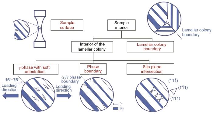
图4
TiAl合金小裂纹萌生位置示意图
Fig.4
Schematic of small crack initiation positions in TiAl alloy
2.2 疲劳小裂纹萌生的主导因素
TiAl合金疲劳小裂纹的萌生受微观组织显著影响。Kruzic等[11]在研究Ti-47Al-2Nb-2Cr-0.2B合金时发现,尽管片层组织具有较高的疲劳裂纹扩展阻力,但其小裂纹更易在片层取向与加载方向垂直的片层团中萌生。在相同疲劳条件(最大应力为片层组织屈服应力的85%)下,片层组织在500 cyc循环内即发生小裂纹的快速萌生,而双态组织在经历500000 cyc循环后仍未见小裂纹萌生。Chan和Shih[33]对比了全片层组织和等轴近γ组织在Ti-47Al-2Nb-2Cr-0.2B合金中的疲劳行为,进一步证实全片层组织中疲劳小裂纹更易萌生。在相同疲劳条件(最大应力为340 MPa)下,在10000 cyc循环内,裂纹迅速在整个片层组织中萌生,而80000 cyc循环后,在等轴近γ组织中没有观察到裂纹的萌生。近γ和双态组织中疲劳小裂纹萌生困难但扩展容易,近片层和全片层组织中疲劳小裂纹萌生容易但扩展困难[11,33]。
图5
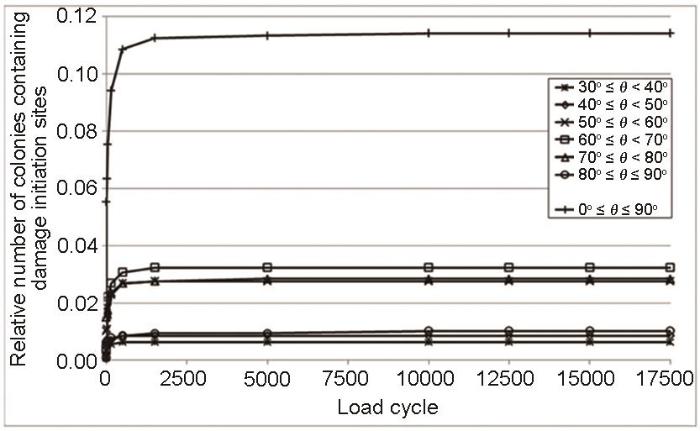
2.3 疲劳小裂纹的扩展机理
Chan和Shih[48]研究了Ti-47Al-2Nb-2Cr合金中疲劳小裂纹的扩展行为,发现晶界对小裂纹扩展具有显著阻碍作用,单个疲劳小裂纹往往难以跨越相邻晶界,导致其扩展速率明显降低,甚至可能在晶界处发生停滞。Wessl等[34]研究表明,Ti-46.5Al-2.5V-1.0Cr合金中的小裂纹萌生于球状γ相内部,初期以I型裂纹在晶粒内扩展,其扩展速率分散性较大(图6[34])。当裂纹扩展到第一个孪晶界时,裂纹扩展停滞或显著延迟。随着载荷水平增加,裂纹在晶粒内恢复扩展,第二个孪晶界对裂纹扩展速率没有明显影响,裂纹尖端通过孪晶界时未受阻碍。此外,Wessl等[34]发现,Ti-43Al-4Nb-1Mo-0.1B合金中最先萌生的小裂纹的扩展行为由第一个片层团的片层结构主导。小裂纹主要沿γ/α2界面扩展,但停留在γ片层内。裂纹在一个片层团内沿着片层方向迅速扩展,在大多数情况下会被片层团界阻碍。在高载荷下,当小裂纹的扩展类型转变为I型(即发生穿片层裂纹扩展)时,裂纹扩展会出现迟滞现象,这表明片层团界和片层相界对TiAl合金的小裂纹扩展具有阻碍作用。片层TiAl合金中,疲劳小裂纹因尺寸有限,导致裂纹闭合和未断裂韧带桥联等外在屏蔽机制难以充分发展,从而表现出较高的有效裂纹驱动力和较快的扩展速率;同时,裂纹尖端与微观结构障碍的相互作用使其扩展行为呈现明显波动[21]。当小裂纹垂直于片层界面扩展时,裂纹扩展阻力最高;当小裂纹与界面成小角度扩展时,阻力最低[11]。
图6

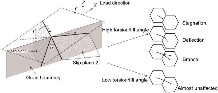
研究[49,50]表明,高扭转角晶界处的裂纹扩展速率明显低于低扭转角晶界,当小裂纹穿过具有较低扭转角和倾斜角的晶界时,其扩展速率基本不受影响,而在穿过具有较高扭转角的晶界时裂纹扩展速率下降。Zhai等[51]认为,晶界扭转角和倾斜角是控制疲劳小裂纹扩展速率和路径的关键因素。而Zhang和Dunne[52]研究表明,倾斜角对接近晶界的小裂纹扩展速率影响很小,但扭转角的增大会导致显著的扩展滞后效应;当裂纹尖端穿过晶界时,较大的扭转角也会导致多滑移系统的激活,从而产生多个裂纹面。如图7[50]所示,小裂纹穿过高扭转角、倾斜角晶界时,将会发生停滞、偏转和分支等现象;小裂纹穿过低扭转角、倾斜角晶界时,则基本不受影响[49~52]。
图7
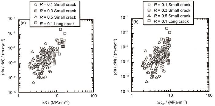
此外,环境因素和应力比也会对TiAl合金疲劳小裂纹的扩展行为产生显著影响。Zhang等[36]研究了高铌TiAl合金在不同温度下的疲劳小裂纹扩展行为,发现高温降低了片层团的相界面强度,疲劳小裂纹更易在片层团内相界面起始;裂纹扩展方向近似垂直于加载轴,表明疲劳小裂纹扩展的早期阶段属于I型,其以多裂纹形式萌生,从而导致多裂纹之间的桥接。Schmiedel等[53]研究了采用电子束粉末床熔融工艺制备的TiAl合金的小裂纹扩展行为,发现在高温下,细晶双相组织中小裂纹的扩展速率较低。图8[21]为疲劳裂纹扩展速率与应力强度因子范围和有效应力强度因子范围的关系。可见,应力比越高,TiAl合金中小裂纹扩展速率越高。
图8
总体而言,TiAl合金中的小裂纹通常沿片层界面解理扩展(即沿着特定晶体学界面发生的脆性、低能量断裂)或沿片层/等轴晶内的低指数晶面扩展。小裂纹萌生后在穿过界面(晶界、孪晶界、片层界面及片层团界)时会受到阻滞,最后扩展为满足线弹性断裂力学的长裂纹。如图9所示,当TiAl合金界面与裂纹扩展方向成大角度(45°~90°)时,仅有少数小裂纹能够扩展并穿过界面,由于受到界面的阻碍,穿过界面的小裂纹发生偏转、分叉等现象,其扩展速率在界面处明显下降。当裂纹扩展方向与界面成小角度(接近0°)时,小裂纹倾向于沿着界面扩展,扩展到一定程度后发生分层现象。界面的阻滞效应主要体现在小裂纹穿过界面这一过程。
图9
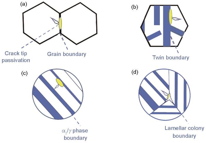
图9
TiAl合金中界面阻碍小裂纹扩展的示意图
Fig.9
Schematics of small crack propagation hindered by interfaces in TiAl alloys
(a) grain boundary (b) twin boundary (c) lamellar boundary (d) lamellar colony boundary
3 疲劳小裂纹寿命预测模型
Chapetti[64]将裂纹闭合效应引入到ΔKth的修正模型中,将ΔKth视为微观结构门槛值(ΔKdR)和门槛值分量(ΔKC)的总和,其中ΔKC是由裂纹闭合引起的,因此ΔKth的表达式为:
式中,k为材料常数;a为裂纹长度;d为微观结构尺寸;Y为几何修正因子;ΔσeR为裂纹持续扩展的应力幅临界值,由小裂纹穿过第一个晶界的临界应力幅所定义。Chapetti模型仅限于描述ΔKth附近的裂纹扩展行为,但仍不适用于描述微观小裂纹阶段的裂纹扩展。
式中,Smax为最大应力,
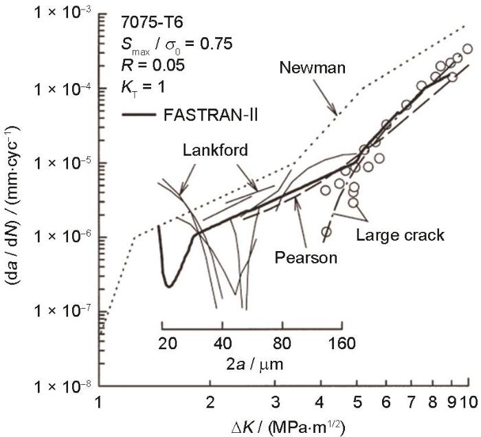
图10
Chan等[68]提出了微观结构差异的概念,认为塑性区晶粒的局部驱动力和断裂韧性的变化是由微观组织的差异引起的,因此,引入了等效应力强度因子范围(ΔK*):
由Tada等[69]推导出的
式中,ΔKd为局部应力强度因子范围;b为裂纹尖端塑性区尺寸;σ为施加的应力;σy为屈服强度;
式中,f1(a)和f2(a)为裂纹尺寸的低阶多项式函数。裂纹形核取决于疲劳载荷在表面附近产生的挤压和侵入效应。Ye等[70]引入了Chan-Lankford模型中的修正因子(q),表达式如下:
式中,Δσ为施加的应力范围,rpc为循环塑性区尺寸,σmax为最大应力。最后得到裂纹扩展速率:
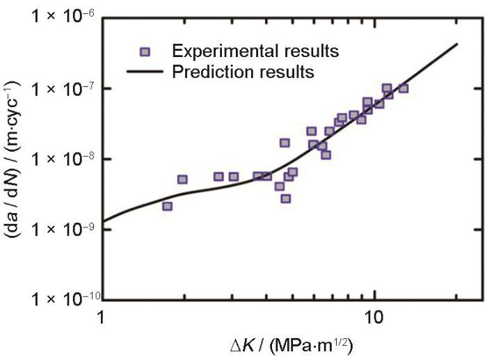
式中,C和n为常量,ΔKths为小裂纹扩展门槛值。TiAl合金小裂纹在扩展过程中发生频繁的偏转和桥接,微观小裂纹扩展路径变得非常曲折,扩展速率波动显著。因此,微观小裂纹扩展速率的预测是建立TiAl合金小裂纹模型研究的一大难点。该多尺度裂纹扩展模型基于晶界强化和微观组织不相似的概念,描述了微观小裂纹的裂纹扩展速率,同时统一了微观小裂纹、物理小裂纹和长裂纹扩展速率的表达式。该模型适用于三维半圆形微观小裂纹扩展为穿透厚度的物理小裂纹/长裂纹的情况。在考虑晶粒尺寸分布的情况下,预测了裂纹扩展速率的最大值和最小值。该模型预测的裂纹扩展速率范围涵盖了微观小裂纹扩展速率的大部分波动,计算结果与实验符合较好,如图11[70]所示。这使得该模型为TiAl合金小裂纹扩展理论研究提供了重要参考。
图11
式中,p为材料相关的裂纹扩展指数参数,表征da / dN对ΔKCPA的敏感程度;在双对数坐标下,p对应于log(da / dN)-log(ΔKCPA)关系曲线的斜率。ΔκCPA为裂纹驱动力,其表达式为[76]:
式中,ΔKCPA为基于临界平面法的ΔK,ΔKCPA,thr为基于临界平面法的循环门槛,ACPA为基于临界平面法的循环断裂韧性。Markham模型合理地解释了裂纹尖端剪切应力减小和轴向应力增大的原因。在Ti-6Al-4V合金中的各种加载条件下,Markham等[76]使用的基于Fatemi-Socie参数修正的ΔKCPA与小裂纹扩展速率具有良好相关性。这使得该模型在建立复杂交变载荷环境下的小裂纹扩展模型时具有很高的参考意义。
裂纹扩展行为受多种因素的影响,如裂纹闭合效应、应力比、门槛值、微观组织、不可逆位错和塑性积累等,单一的模型中不可能包含所有的因素。此外,TiAl合金中的长裂纹表现出尖端小范围屈服的特征。因此,亟需发展能够同时描述TiAl合金小裂纹和长裂纹扩展行为的统一寿命预测模型。
4 总结与展望
本文围绕TiAl合金疲劳小裂纹问题,系统介绍了疲劳小裂纹定义及特点,归纳总结了TiAl合金疲劳小裂纹的萌生和扩展机理、疲劳小裂纹扩展模型及其适用范围。TiAl合金疲劳小裂纹萌生主导应变存在两种观点:一种认为小裂纹萌生是剪切应变主导,证据是裂纹萌生方向与加载轴成60°~80°夹角;另一种认为小裂纹萌生是法向应变主导,证据是小裂纹从高法向应变处萌生。TiAl合金疲劳小裂纹扩展受晶界、孪晶界、片层界面及片层团界面影响,界面既可能是扩展屏障,也可能是扩展通道。小裂纹垂直于界面扩展时,扩展阻力最高,界面阻碍裂纹扩展;小裂纹扩展方向与界面夹角越小,扩展阻力越小;当夹角角度降至临界值以下时,小裂纹沿界面扩展。TiAl合金小裂纹萌生位置受应力和温度影响。随着应力降低,小裂纹萌生位置由表面转向内部;随着温度升高,小裂纹倾向于在片层团界和片层相界处萌生。
未来研究可从以下几个方向开展。
(1) 原位表征与多尺度模拟融合。针对TiAl合金小裂纹萌生位置和主导因素认识不一、现有实验手段难以精准捕捉的难题,需发展同步追踪微观结构与局部应变场演化的原位实验监测系统,结合多尺度模拟方法,实现小裂纹萌生位置的精确表征并揭示主导因素。进一步聚焦界面的双重作用,揭示不同条件下界面作为扩展屏障与扩展通道的竞争机制,建立裂纹扩展阻力与裂纹/界面偏转角度的内在关联。
(2) 复杂服役环境下的小裂纹行为。当前研究多集中于单一温度和常规加载条件,而空天动力用TiAl构件在实际服役时往往承受温度、应力比、频率、保载时间、氧化环境及复杂交变载荷的耦合作用。亟需阐明复杂加载条件下小裂纹的萌生和扩展规律,建立贴近工程服役条件的TiAl合金疲劳小裂纹性能数据库。
(3) 小裂纹与长裂纹统一寿命预测模型。针对TiAl合金小裂纹扩展速率波动显著、长裂纹尖端呈现小范围屈服等特征给统一寿命预测带来的挑战,亟需发展能够同时描述小裂纹与长裂纹扩展行为的统一寿命预测模型,突破现有方法难以兼顾二者的瓶颈。
(4) 考虑组织敏感性的抗疲劳设计。立足疲劳小裂纹行为对组织高度敏感的损伤本质,基于小裂纹萌生和扩展机理,建立组织特征参数与疲劳寿命间的内在关联,阐明不同组织形态对疲劳小裂纹萌生和扩展阻力的调控规律。将小裂纹行为研究与合金组织设计结合,形成面向服役需求的抗疲劳TiAl合金组织设计准则。
参考文献
Polysynthetic twinned TiAl single crystals for high-temperature applications
[J].
TiAl alloys are lightweight, show decent corrosion resistance and have good mechanical properties at elevated temperatures, making them appealing for high-temperature applications. However, polysynthetic twinned TiAl single crystals fabricated by crystal-seeding methods face substantial challenges, and their service temperatures cannot be raised further. Here we report that Ti-45Al-8Nb single crystals with controlled lamellar orientations can be fabricated by directional solidification without the use of complex seeding methods. Samples with 0 degrees lamellar orientation exhibit an average room temperature tensile ductility of 6.9% and a yield strength of 708 MPa, with a failure strength of 978 MPa due to the formation of extensive nanotwins during plastic deformation. At 900 degrees C yield strength remains high at 637 MPa, with 8.1% ductility and superior creep resistance. Thus, this TiAl single-crystal alloy could provide expanded opportunities for higher-temperature applications, such as in aeronautics and aerospace.
Aircraft gas turbine materials and processes
[J].Materials and processing innovations that have been incorporated into the manufacture of critical components for high-performance aircraft gas turbine engines are described. The materials of interest are the nickel- and cobalt-base superalloys for turbine and burner sections of the engine, and titanium alloys and composites for compressor and fan sections of the engine. Advanced processing methods considered include directional solidification, hot isostatic pressing, superplastic foring, directional recrystallization, and diffusion brazing. Future trends in gas turbine technology are discussed in terms of materials availability, substitution, and further advances in air-cooled hardware.
Intermetallics: Why is it so difficult to introduce them in gas turbine engines?
[J].
Research progress on additive manufacturing TiAl alloy
[J].One of the most promising high-temperature structural materials in aerospace and civil industries is the lightweight and heat-resistant TiAl alloys. However, owing to their low ductility and fracture toughness, manufacturing TiAl parts is challenging. At present, additive manufacturing process is considered one of the most promising technologies for manufacturing TiAl parts. Based on the principles and characteristics of additive manufacturing technology, this paper summarizes the process-structure-property relation of laser metal deposition (LMD), selective laser melting (SLM), and electron beam melting (EBM) in the preparation of TiAl alloy. Furthermore, this paper discusses the future development trends of additive manufacturing technology.
增材制造TiAl合金的研究进展
[J].轻质耐热的TiAl合金是航空航天和民用工业等领域最具潜力的高温结构材料之一。然而,由于其低的延展性和断裂韧性,制造TiAl零部件具有挑战性。目前,增材制造工艺被认为是制造TiAl零件具有前途的技术之一。本文在介绍增材制造技术原理和特点的基础上,综述了激光金属沉积(LMD)、选区激光熔化(SLM)和电子束熔化(EBM)制备TiAl合金的工艺-组织-性能关系,并对该技术未来的发展趋势进行了展望。
Polysynthetic twinned high-performance TiAl alloy with ordered structures of functional units
[J].Transformative TiAl alloys are in high demand for hot-end components such as aeroengine blades and for lightweighting advanced aerospace equipment. However, traditional TiAl alloys are brittle at room temperature and exhibit low long-term capability at high temperatures. To overcome these limitations, our team has proposed a new material-design paradigm based on “ordered structures of functional units.” By precisely regulating the intrinsic characteristics and ordered structures of the soft γ-TiAl phase, the hard α2-Ti3Al phase, and nano-twins, we considerably enhance the strength, plasticity, and high-temperature capability of polysynthetic twinned TiAl alloys. We also demonstrate the decisive roles of ordered-structure parameters, such as interface type, lamellar orientation, lamellar thickness, and phase proportion, on the mechanical properties of the alloy. The physical strengthening and toughening mechanisms include twinning-induced strengthening and plasticity in the γ phase, fatigue-strength-enhancing stacking faults in the α2 phase, toughening via transformation of the α2 phase, and γ/α2 coherent interfaces, which improve fracture toughness. These insights illuminate promising directions for the development of TiAl alloys with ordered functional unit structures.
聚片孪生功能基元序构的高性能TiAl合金
[J].
TiAl alloys in commercial aircraft engines
[J].
Research progress of multiaxial fatigue test methods on blades of aviation engine
[J].
航空发动机叶片多轴疲劳试验研究进展
[J].近几年航空发动机叶片失效分析的统计表明,叶片失效多由离心力叠加异常振动的多轴疲劳载荷引起。总结现有单一载荷加载、双轴载荷加载等多轴疲劳试验方法的优缺点,并分析其在评价航空发动机叶片多轴疲劳时存在的问题。重点介绍目前国际上最新研制的可有效模拟发动机叶片受力状态的拉伸-弯曲振动多轴疲劳试验方法。建议尽快建立适合我国航空发动机叶片的多轴疲劳试验系统。
The behaviour of short fatigue cracks and their initiation part II—A general summary
[J].
Small fatigue crack growth behavior of TB6 titanium alloy
[J].The growth behavior of naturally-initiated small cracks in single edge notched tensile (SENT) specimen of TB6 titanium alloy was studied. Fatigue experiments were conducted under constant amplitude loading with the stress ratios <em>R</em> of 0.1 and 0.5 at room temperature. Small cracks were allowed to be monitored by replica method during fatigue testing. Results show that at the same stress ratio, the initiation life of crack increases from 60% to 80% of the total fatigue life with the decrease of stress level. However, the stress level has no significant effect on the crack growth rate of TB6 titanium alloy. The crack growth rate at the early stage is greatly affected by the microstructure. Once the crack length reaches 200μm, the crack growth rate will increase rapidly regardless of grain boundary or grain orientation. Small cracks of TB6 titanium alloy are originated from the sample notch root in the form of corner crack, and the major part of total fatigue life is consumed in small fatigue crack initiation phase.
TB6钛合金疲劳小裂纹扩展行为
[J].
On the fatigue behavior of γ-based titanium aluminides: Role of small cracks
[J].
Initiation of fatigue cracks in commercial aluminium alloys and the subsequent propagation of very short cracks
[J].
Small‐crack growth and fatigue life predictions for high‐strength aluminium alloys. Part II: Crack closure and fatigue analyses
[J].Small‐crack effects were investigated in two high‐strength aluminium alloys: 7075‐T6 bare and LC9cs clad aluminium alloys. Both experimental and analytical investigations were conducted to study crack initiation and growth of small cracks. In the experimental program, fatigue and small‐crack tests were conducted on single‐edge‐notch tension (SENT) specimens and large‐crack tests were conducted on middle‐crack tension specimens under constant‐amplitude and Mini‐TWIST spectrum loading. A pronounced small‐crack effect was observed in both materials, especially for the negative stress ratios. For all loading conditions, most of the fatigue life of the SENT specimens was shown to be crack propagation from initial material defects or from the cladding layer. In the analysis program, three‐dimensional finite‐element and weight‐function methods were used to determine stress intensity factors, and to develop equations for surface and corner cracks at the notch in the SENT specimen. (Part I was on the experimental and fracture mechanics analyses and was published inFatigue Fract. Engng Mater. Struct.21, 1289–1306, 1998.) This part focuses on a crack closure and fatigue analysis of the data presented in Part I. A plasticity‐induced crack‐closure model was used to correlate large‐crack growth rate data to develop the baseline effective stress intensity factor range (ΔKeff ) against rate relations for each material, ignoring the large‐crack threshold. The model was then used with the ΔKeffrate relation and the stress intensity factors for surface or corner cracks to make fatigue life predictions. The initial defect sizes chosen in the fatigue analyses were similar to those that initiated failure in the specimens. Predicted small‐crack growth rates and fatigue lives agreed well with experiments.
A critical assessment of fatigue crack nucleation and growth models for Ni- and Ni,Fe-based superalloys
[J].
A small-crack growth law and its related phenomena
[J].
Fatigue behavior of nanocrystalline metals and alloys
[J].
Propagation behaviors of small cracks in powder metallurgy nickel-based superalloy FGH4096
[J].Inevitable nonmetallic inclusions (NMIs) exist in powder metallurgy (PM) superalloys. These inclusions serve as preferred sites for crack initiation either by fracture of inclusions or inclusion/matrix decohesion. After initiating from NMIs, fatigue cracks will experience the small crack propagation phase. Small fatigue cracks could grow under the fatigue crack growth threshold and propagate at a vibrated rate. To investigate the propagation behavior and reveal the underlying mechanisms, small crack propagation experiments under fatigue loads of different maximum stresses were conducted on PM superalloy FGH4096 using the small fatigue crack-propagation experiment system. The characterization of microstructure was conducted and orientations of grains were calibrated using SEM integrated with EBSD. Focusing on the three-dimensional nature and the physical basis, the propagation and stagnation behavior of small cracks were revealed. Experimental results showed that the small cracks propagated along octahedral slip planes, from initiation to a length even longer than 1.0 mm. During the propagation in the grain-containing twin, small cracks grew along the direction parallel to the twin boundary. However, several twin boundaries impeded crack growth. Small cracks were stagnated at grain and twin boundaries of which M factors were lower than adjacent ones. Three behaviors were observed after the stagnation of small cracks due to the different properties of grain/twin boundaries and the applied load; first, stagnated small cracks could continue to propagate by consuming more cycles; second, small cracks could propagate by alternating to another slip plane in current or other grains on the crack path; third, secondary cracks would initiate within 1-2 grains from the tip of the fully stagnated cracks and connected to the main crack. This behavior was observed only in the specimen in which the maximum stress is close to the lower limit of the yield strength.
粉末高温合金FGH4096的疲劳小裂纹扩展行为
[J].以粉末高温合金FGH4096为研究对象,开展了2个不同最大应力条件下的疲劳小裂纹扩展实验。利用SEM结合EBSD观察了小裂纹扩展路径,表征了扩展路径上晶粒的取向,重点从小裂纹的三维属性和扩展物理基础出发,研究了小裂纹的扩展和停滞行为。结果表明:小裂纹自萌生到总长度超过1.0 mm后始终保持沿八面体滑移面扩展的行为;晶界和孪晶界是阻碍小裂纹扩展、导致小裂纹扩展停滞的微观组织,这些晶界/孪晶界的M因子都较邻近晶界的M因子低,表明M因子可用作表征晶界/孪晶界阻碍小裂纹扩展的能力。根据晶界性质和载荷的不同,小裂纹在晶界/孪晶界处发生扩展停滞后可以有3种行为:一是在经历一定循环数后,裂纹穿越晶界继续扩展;二是在裂纹停滞期间,裂纹转到所在晶粒内的其他滑移面或沿扩展路径上其他晶粒内的滑移面继续扩展;三是二次裂纹在停滞的主裂纹尖端附近1~2个晶粒范围萌生,并与主裂纹连接后继续扩展成为新的主裂纹,该裂纹行为仅出现在最大应力接近屈服强度范围下限的试样中。
The growth of small fatigue cracks in a low carbon steel; the effect of microstructure and limitations of linear elastic fracture mechanics
[J].
Model for predicting fatigue life and limit of steels based on micromechanics of small crack growth
[J].
Propagation behavior of small and long fatigue cracks in TiAl alloy at elevated temperature
[J].
TiAl合金高温疲劳小裂纹与长裂纹扩展行为
[J].
Effect of stress ratio on fatigue crack growth in TiAl intermetallics at room and elevated temperatures
[J].
Short fatigue crack growth under mean stress, uniaxial loading
[J].
Propagation of short fatigue cracks
[J].
Effects of tensile load hold time on the fatigue and corrosion-fatigue behavior of turbine blade materials
[J].
Fatigue threshold and crack propagation in γ-TiAl sheets
[J].
Review of fatigue small cracks in key components of gas turbine engines
[J].
燃气涡轮发动机关键部件疲劳小裂纹研究进展
[J].
Microscopic process and description for the initiation and propagation of short fatigue cracks
[J].
疲劳短裂纹萌生及发展的细观过程和理论
[J].
Small fatigue cracks: A statement of the problem and potential solutions
[J].
Initiation and growth of small fatigue crack in TiAl intermetallics at elevated and room temperatures
[J]. J.
Effects of V and B on the microstructure evolution and deformation mechanisms of Ti-44Al-5Nb-1Mo alloys
[J].
V和B元素对Ti-44Al-5Nb-1Mo合金显微组织及热变形机制的影响
[J].为了探究V和B元素复合添加对β型γ-TiAl合金的显微组织和变形机制产生的影响,本工作针对Ti-44Al-5Nb-1Mo合金和Ti-44Al-5Nb-1Mo-2V-0.2B合金,进行了不同温度和应变速率条件下的高温热压缩实验,利用SEM-BSE和TEM对组织进行表征,对比分析了其变形后的显微组织,研究了添加V和B对Ti-44Al-5Nb-1Mo合金的显微组织及热变形机制的影响。结果表明,2种TiAl合金的显微组织差异较大,添加V和B可以显著改变TiAl合金对热变形的敏感性。Ti-44Al-5Nb-1Mo-2V-0.2B合金高温变形能力明显优于Ti-44Al-5Nb-1Mo合金。Ti-44Al-5Nb-1Mo合金的高温热变形以难变形片层团的偏转、变形带的产生为主,温度为1250℃时,其变形组织表现出较高的温度和应变速率敏感性,极易形成尺寸不均匀的近片层组织;对于Ti-44Al-5Nb-1Mo-2V-0.2B合金而言,升高变形温度或降低应变速率,既可以促进片层团内部的变形诱导L(α/γ)→α + γ + β/B2和γ→α相变,又可以促进α和β/B2相的球化/动态再结晶,从而大幅提高该合金的组织均匀性。基于变形参数对组织的影响规律,确定了控制Ti-44Al-5Nb-1Mo和Ti-44Al-5Nb-1Mo-2V-0.2B合金中近全片层、近双态显微组织的方法。
Solidification behavior and microstructures characteristics of Ti-48Al-3Nb-1.5Ta powder produced by supreme-speed plasma rotating electrode process
[J].
Fundamental aspects of fatigue and fracture in a TiAl sheet alloy
[J].
Short fatigue cracks in intermetallic γ-TiAl-alloys
[J].
Recent progress in the high-cycle fatigue behaviour of γ-TiAl alloys
[J].
Fatigue small crack growth threshold determination of a high-Nb TiAl alloy at different temperatures by in-situ observation
[J].
Investigation of fatigue small crack propagation of TiAl alloy at 750 oC
[J].
TiAl合金750 ℃下疲劳小裂纹行为研究
[J].
Theory of brittle fracture in steel and similar metals
[J].
Persistent microslip bands in the lamellar TiAl structure subjected to room temperature fatigue
[J].
Features of fracture surface in a fully lamellar TiAl-base alloy
[J].
Microstructural characterisation of fatigue crack growth fracture surfaces of lamellar Ti45Al2Mn2Nb1B
[J].
Local deformation at micro‐notches and crack initiation in an intermetallic γ‐TiAl‐alloy
[J].
A dislocation model for fatigue crack initiation
[J].The slip band formed in a grain on the material surface is a preferential site for crack initiation during low strain fatigue of polycrystalline metals. The forward and reverse plastic flow within the slip band is modeled in the present study by dislocations with different signs moving on two closely located layers, and it is assumed that their movement is irreversible. Based on the model, the monotonic buildup of dislocation dipoles piled up at the grain boundary is systematically derived using the theory of continuously distributed dislocations. This buildup is associated with the progress of extrusion or intrusion. The number of stress cycles up to the initiation of a crack of the grain size order is defined as the cycle when the stored strain energy of accumulated dislocations reaches a critical value. The relation between the initiation life and the plastic strain range derived theoretically is in agreement with a Coffin-Manson type law, and that between the fatigue strength and the grain size is expressed in an equation of the Petch type.
Investigation of small crack behaviour under cyclic loading in a dual phase steel with an FIB tomography technique
[J].
Physically short crack propagation in metals during high cycle fatigue
[J].
Fatigue crack closure: A review of the physical phenomena
[J].
In-situ experimental investigation on fatigue crack growth behavior and crack tip plastic zone evolution of laser powder bed fused TiC/Ti6Al4V composites
[J].
Fatigue and fracture behavior of a fine-grained lamellar TiAl alloy
[J].
A grain boundary interaction model for microstructurally short fatigue cracks
[J].
Quantification of resistance of grain boundaries to short-fatigue crack growth in three dimensions in high-strength Al alloys
[J].
The grain boundary geometry for optimum resistance to growth of short fatigue cracks in high strength Al-alloys
[J].
3D CP-XFEM modelling of short crack propagation interacting with twist/tilt nickel grain boundaries
[J].
Very high cycle fatigue properties at 973 K of additively manufactured and conventionally processed intermetallic TiAl 48-2-2 alloy
[J].
Research on short fatigue crack initiation and propagation of metallic materials: A review
[J].
金属材料疲劳短裂纹萌生与扩展研究综述
[J].系统梳理了金属材料疲劳短裂纹的定义、分类、试验方法、萌生机理及典型扩展率模型,对当前短裂纹行为研究面临的问题进行了总结与展望。研究结果表明,在萌生机理方面,材料自身的微观结构对短裂纹萌生及扩展有重要影响,短裂纹扩展至晶界处,受晶粒取向及晶界阻力影响,扩展率会下降,裂尖突破晶界束缚后,短裂纹扩展路径出现局部偏折。在扩展行为描述方面,短裂纹的扩展驱动力与承受的载荷水平、残余应力、表面处理方式、局部磨损状况等有关。扩展过程中,裂纹尖端材料在小范围内屈服而产生局部塑性区。同时,塑性尾迹区也逐渐形成,进而产生塑性诱导闭合,导致裂纹扩展门槛值降低。此外,晶体位错之间的相互作用和位错塞积会阻碍位错发展。机器学习算法作为一种先进技术手段,已在短裂纹扩展行为表征中得到应用,对提升预测精度有促进作用。随着金属材料短裂纹行为研究的进一步深入,未来可重点关注短裂纹萌生与扩展实时监测、试验影响因素控制、数据离散性分析、扩展率模型的工程应用等问题,探索建立适用于工程结构与零部件的在役长、短裂纹扩展率统一表征模型和实时监测与安全评估技术,结合先进的机器学习算法,实现对工程关键金属结构更有效、更准确的安全性评定和剩余寿命管理。
Fatigue crack growth modelling based on CTOD for the 7050-T6 alloy
[J].
Fatigue crack propagation in steels
[J].
A crack-tip strain model for the growth of small fatigue cracks
[J].
A small fatigue crack growth relationship and its application to cast aluminum
[J].
In-situ SEM investigation and modeling of small crack growth behavior of additively manufactured titanium alloy
[J].
A unified threshold model for physically small and long crack based on CTOD
[J].
Fatigue crack growth during gross plasticity and the J-integral
[R].
Short crack growth and fatigue life in austenitic-ferritic duplex stainless steel
[J].
Short fatigue crack growth under nonproportional multiaxial elastic-plastic strains
[J].
Fatigue propagation threshold of short cracks under constant amplitude loading
[J].
A crack-closure model for predicting fatigue-crack growth under aircraft spectrum loading
[R].
Fatigue-life prediction methodology using small-crack theory
[J].
Fatigue-life prediction method based on small-crack theory in an engine material
[J].
A comparison of crack-tip field parameters for large and small fatigue cracks
[J].A comparison of the elastic-plastic crack-tip fields of large and small fatigue cracks has been made using the ΔJ-integral approach. Using experimental strain and displacement range measurements obtained by means of the stereoimaging technique, the ΔJ-integral has been computed for an aluminum alloy containing either large or small fatigue cracks, by performing line-contour integration along a variety of rectangular paths around the crack tip. These calculations reveal that for both large and small cracks the ΔJ-integral is path-dependent, and that the value of ΔJ increases with decreasing distance from the crack tip. Using an average local ΔJ or one estimated from the CTOD, the enhanced crack growth rates associated with small fatigue cracks can be explained on the basis of the large average ΔJ-integral within the cyclic plastic zone. The effect of crack closure on the computed local ΔJ (or ΔK) and crack growth is discussed.
Multi‐scale fatigue crack propagation in 304 stainless steel: Experiments and modelling
[J].
Characterising and representing small crack growth in an additive manufactured titanium alloy
[J].
Representing crack growth in additively manufactured Ti-6Al-4V
[J].
Crack growth in a range of additively manufactured aerospace structural materials
[J].The aerospace industry is now beginning to adopt Additive Manufacturing (AM), both for new aircraft design and to help improve aircraft availability (aircraft sustainment). However, MIL-STD 1530 highlights that to certify airworthiness, the operational life of the airframe must be determined by a damage tolerance analysis. MIL-STD 1530 also states that in this process, the role of testing is merely to validate or correct the analysis. Consequently, if AM-produced parts are to be used as load-carrying members, it is important that the d a / d N versus ΔK curves be determined and, if possible, a valid mathematical representation determined. The present paper demonstrates that for AM Ti-6Al-4V, AM 316L stainless steel, and AM AerMet 100 steel, the d a / d N versus ΔK curves can be represented reasonably well by the Hartman-Schijve variant of the NASGRO crack growth equation. It is also shown that the variability in the various AM d a / d N versus Δ K curves is captured reasonably well by using the curve determined for conventionally manufactured materials and allowing for changes in the threshold and the cyclic fracture toughness terms.
Modelling the variability and the anisotropic behaviour of crack growth in SLM Ti-6Al-4V
[J].The United States Air Force (USAF) Guidelines for the Durability and Damage Tolerance (DADT) certification of Additive Manufactured (AM) parts states that the most difficult challenge for the certification of an AM part is to establish an accurate prediction of its DADT. How to address this challenge is the focus of the present paper. To this end this paper examines the variability in crack growth in tests on additively manufactured (AM) Ti-6Al-4V specimens built using selective layer melting (SLM). One series of tests analysed involves thirty single edge notch tension specimens with five build orientations and two different post heat treatments. The other test program analysed involved ASTM standard single edge notch specimens with three different build directions. The results of this study highlight the ability of the Hartman–Schijve crack growth equation to capture the variability and the anisotropic behaviour of crack growth in SLM Ti-6Al-4V. It is thus shown that, despite the large variability in crack growth, the intrinsic crack growth equation remains unchanged and that the variability and the anisotropic nature of crack growth in this test program is captured by allowing for changes in both the fatigue threshold and the cyclic fracture toughness.
The effects of environment and load frequency on the crack propagation law for macro fatigue crack growth in aluminium alloys
[J].


