An analytical model for the heat generation in friction stir welding
1
2004
... 搅拌摩擦焊(friction stir welding,FSW)问世30余年以来,已广泛应用于运载火箭贮箱、高铁列车车体、新能源汽车电池等关键结构的制造中.然而,对FSW物理过程的认识仍大幅落后于其工程应用进程.FSW物理过程具有鲜明特征:材料虽不发生熔化,但在流经搅拌头附近的数秒时间内发生剧烈的塑性流动并沉积焊缝中.目前,针对FSW材料流动的研究大多集中在分析材料流动的速度及其分布[1~8],但由于在实验观测上缺少有效的研究手段,对材料流经搅拌头附近的完整轨迹仍缺少深入认识. ...
A conceptual model for the process variables related to heat generation in friction stir welding of aluminum
0
2008
Computational fluid dynamics studies on heat generation during friction stir welding of aluminum alloy
1
2013
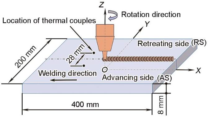
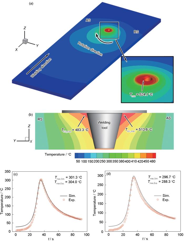
... 图3a给出了FSW过程中工件表面的温度分布预测结果.可以看出,轴肩与搅拌针根部连接处出现局部高温区,最高温度为524.1 ℃,位于搅拌头侧后方.搅拌头前方的温度梯度明显高于后方,符合焊接温度场的典型特征.图3b给出了经过搅拌头旋转中心X = 0 mm截面上的温度分布情况.在搅拌针与工件界面附近的温度分布并不均匀,形成了碗状的局部高温区域,AS的最高温度为513.6 ℃,而RS的最高温度为483.3 ℃,焊接过程中AS的温度高于RS的现象,与其他学者[3,4]的实验和仿真结果一致.为验证温度场预测结果的可靠性,将仿真结果与测温结果进行对比.图3c和d给出了图1所示热电偶安装处温度仿真结果与实测结果.距离焊缝中心线Y = -14 mm、Z = 7 mm处AS位置的预测最高温度为301.3 ℃,实测最高温度为304.0 ℃.距离焊缝中心线Y = 14 mm、Z = 7 mm处RS位置的预测最高温度为296.7 ℃,实测最高温度为288.3 ℃.测温点的最高温度预测结果与实验结果之间的误差均在3%以内.这表明,本工作构建的仿真模型在预测FSW的过程温度场方面具有很高的精度.FSW过程中搅拌头附近高温软化的材料发生塑性流动,准确的温度场预测模型为下文分析材料流动奠定了基础. ...
Thermal energy generation and distribution in friction stir welding of aluminum alloys
1
2014
... 图3a给出了FSW过程中工件表面的温度分布预测结果.可以看出,轴肩与搅拌针根部连接处出现局部高温区,最高温度为524.1 ℃,位于搅拌头侧后方.搅拌头前方的温度梯度明显高于后方,符合焊接温度场的典型特征.图3b给出了经过搅拌头旋转中心X = 0 mm截面上的温度分布情况.在搅拌针与工件界面附近的温度分布并不均匀,形成了碗状的局部高温区域,AS的最高温度为513.6 ℃,而RS的最高温度为483.3 ℃,焊接过程中AS的温度高于RS的现象,与其他学者[3,4]的实验和仿真结果一致.为验证温度场预测结果的可靠性,将仿真结果与测温结果进行对比.图3c和d给出了图1所示热电偶安装处温度仿真结果与实测结果.距离焊缝中心线Y = -14 mm、Z = 7 mm处AS位置的预测最高温度为301.3 ℃,实测最高温度为304.0 ℃.距离焊缝中心线Y = 14 mm、Z = 7 mm处RS位置的预测最高温度为296.7 ℃,实测最高温度为288.3 ℃.测温点的最高温度预测结果与实验结果之间的误差均在3%以内.这表明,本工作构建的仿真模型在预测FSW的过程温度场方面具有很高的精度.FSW过程中搅拌头附近高温软化的材料发生塑性流动,准确的温度场预测模型为下文分析材料流动奠定了基础. ...
Material flow in FSW of AA7075-T6 butt joints: Continuous dynamic recrystallization phenomena
0
2006
Prediction of temperature and residual stress distributions in friction stir welding of aluminum alloy
0
2020
Friction stir welding/processing of metals and alloys: A comprehensive review on microstructural evolution
0
2021
Numerical simulation of heat generation, heat transfer and material flow in friction stir welding
1
2018
... 搅拌摩擦焊(friction stir welding,FSW)问世30余年以来,已广泛应用于运载火箭贮箱、高铁列车车体、新能源汽车电池等关键结构的制造中.然而,对FSW物理过程的认识仍大幅落后于其工程应用进程.FSW物理过程具有鲜明特征:材料虽不发生熔化,但在流经搅拌头附近的数秒时间内发生剧烈的塑性流动并沉积焊缝中.目前,针对FSW材料流动的研究大多集中在分析材料流动的速度及其分布[1~8],但由于在实验观测上缺少有效的研究手段,对材料流经搅拌头附近的完整轨迹仍缺少深入认识. ...
搅拌摩擦焊接产热传热过程与材料流动的数值模拟
1
2018
... 搅拌摩擦焊(friction stir welding,FSW)问世30余年以来,已广泛应用于运载火箭贮箱、高铁列车车体、新能源汽车电池等关键结构的制造中.然而,对FSW物理过程的认识仍大幅落后于其工程应用进程.FSW物理过程具有鲜明特征:材料虽不发生熔化,但在流经搅拌头附近的数秒时间内发生剧烈的塑性流动并沉积焊缝中.目前,针对FSW材料流动的研究大多集中在分析材料流动的速度及其分布[1~8],但由于在实验观测上缺少有效的研究手段,对材料流经搅拌头附近的完整轨迹仍缺少深入认识. ...
Material flow in butt friction stir welds in AA2024-T3
4
2006
... 为探究FSW过程中材料流动-沉积行为,研究人员通过实验和数值模拟进行了广泛研究,包括示踪剂追踪技术[9~15]和数值计算方法[16~23],许多基于实验和模拟的研究揭示了材料在搅拌头周围表现出多圈绕流模式和直通流动模式[23~28].实验可视化研究主要通过引入与母材物性存在差异的材料作为标记物来实现,利用实验表征手段直接呈现材料流动过程[23,29].研究人员采用铜条[9]、钨球[10]、铜箔[12]、增厚氧化层[13]和异种焊丝[14]等材料作为标记物,追踪材料的流动轨迹和沉积位置.但是采用追踪材料的实验方法也存在一定的局限性.Schimdt等[9]通过焊缝中心纵向、焊缝横向位置设置0.1 mm厚铜条作为追踪材料,对FSW过程的试板进行计算机断层扫描(CT)分析,观察到追踪材料在轴肩部位呈“S”形或“C”形轨迹,并从材料流动速度和沉积位置,判断出材料在沉积前完成多次旋转,由于实验的局限性,无法定量给出某点追踪材料的流动轨迹和沉积位置.Morisada等[10]分别在A1050铝合金和低碳钢搅拌区焊缝中心预制孔中嵌入钨球,搅拌区±30°的位置放置了两组X射线透射系统,通过观察,钨示踪剂材料在铝合金焊缝搅拌头周围存在多圈绕流现象并有沿垂向方向的迁移,而钨示踪剂材料在低碳钢焊缝中直接绕过后退侧沉积在搅拌头后方,呈现出直通绕流模式,实验中,由于钨球嵌入的位置有限,无法全面反映整个焊接区域的材料流动行为.Huang等[12]和Zeng等[13]采用人工增厚氧化层和分层铜箔直接追踪材料水平流动和垂向流动过程的迁移行为,但是未有效获得三维流动模型.因而,目前FSW材料流动-沉积行为的实验表征研究主要集中在搅拌过程中的材料迁移机理,即焊缝宏观结构的形成,关于材料流动过程中三维空间下的流速、应变及应变速率等关键物理参量的实验表征研究仍严重不足[23,29],且缺乏对材料流经搅拌头复杂几何区域周围完整的轨迹认识. ...
... [9]、钨球[10]、铜箔[12]、增厚氧化层[13]和异种焊丝[14]等材料作为标记物,追踪材料的流动轨迹和沉积位置.但是采用追踪材料的实验方法也存在一定的局限性.Schimdt等[9]通过焊缝中心纵向、焊缝横向位置设置0.1 mm厚铜条作为追踪材料,对FSW过程的试板进行计算机断层扫描(CT)分析,观察到追踪材料在轴肩部位呈“S”形或“C”形轨迹,并从材料流动速度和沉积位置,判断出材料在沉积前完成多次旋转,由于实验的局限性,无法定量给出某点追踪材料的流动轨迹和沉积位置.Morisada等[10]分别在A1050铝合金和低碳钢搅拌区焊缝中心预制孔中嵌入钨球,搅拌区±30°的位置放置了两组X射线透射系统,通过观察,钨示踪剂材料在铝合金焊缝搅拌头周围存在多圈绕流现象并有沿垂向方向的迁移,而钨示踪剂材料在低碳钢焊缝中直接绕过后退侧沉积在搅拌头后方,呈现出直通绕流模式,实验中,由于钨球嵌入的位置有限,无法全面反映整个焊接区域的材料流动行为.Huang等[12]和Zeng等[13]采用人工增厚氧化层和分层铜箔直接追踪材料水平流动和垂向流动过程的迁移行为,但是未有效获得三维流动模型.因而,目前FSW材料流动-沉积行为的实验表征研究主要集中在搅拌过程中的材料迁移机理,即焊缝宏观结构的形成,关于材料流动过程中三维空间下的流速、应变及应变速率等关键物理参量的实验表征研究仍严重不足[23,29],且缺乏对材料流经搅拌头复杂几何区域周围完整的轨迹认识. ...
... [9]通过焊缝中心纵向、焊缝横向位置设置0.1 mm厚铜条作为追踪材料,对FSW过程的试板进行计算机断层扫描(CT)分析,观察到追踪材料在轴肩部位呈“S”形或“C”形轨迹,并从材料流动速度和沉积位置,判断出材料在沉积前完成多次旋转,由于实验的局限性,无法定量给出某点追踪材料的流动轨迹和沉积位置.Morisada等[10]分别在A1050铝合金和低碳钢搅拌区焊缝中心预制孔中嵌入钨球,搅拌区±30°的位置放置了两组X射线透射系统,通过观察,钨示踪剂材料在铝合金焊缝搅拌头周围存在多圈绕流现象并有沿垂向方向的迁移,而钨示踪剂材料在低碳钢焊缝中直接绕过后退侧沉积在搅拌头后方,呈现出直通绕流模式,实验中,由于钨球嵌入的位置有限,无法全面反映整个焊接区域的材料流动行为.Huang等[12]和Zeng等[13]采用人工增厚氧化层和分层铜箔直接追踪材料水平流动和垂向流动过程的迁移行为,但是未有效获得三维流动模型.因而,目前FSW材料流动-沉积行为的实验表征研究主要集中在搅拌过程中的材料迁移机理,即焊缝宏观结构的形成,关于材料流动过程中三维空间下的流速、应变及应变速率等关键物理参量的实验表征研究仍严重不足[23,29],且缺乏对材料流经搅拌头复杂几何区域周围完整的轨迹认识. ...
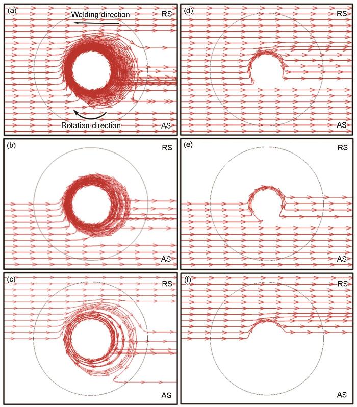
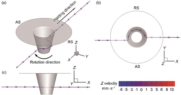
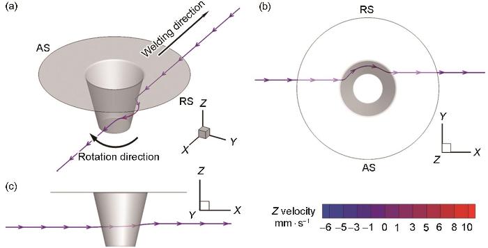
... 图8给出了Z = 7 mm和Z = 3 mm两个典型平面材料流动轨迹的分布情况.图8a~c给出了Z = 7 mm平面位置的材料流动轨迹.该区域的材料流动主要由轴肩驱动,无论是AS还是RS的材料,均在搅拌头周围经历了多次环绕,形成了多圈绕流区,最后沉积在搅拌头后方.这种绕流区在Schmidt等[9]的实验研究和Morisada等[10]的原位观测中均得到证实.材料的绕流范围始终限制在轴肩区域内,这是由于材料在轴肩范围内的流动宽度小于轴肩尺寸(图5).图8d~f给出了在Z = 3 mm平面位置的材料流动轨迹.该区域主要由搅拌针驱动,材料无法完全绕搅拌针旋转整圈,材料绕过搅拌针后直接沉积在搅拌头后方.值得注意的是,由于该位置更靠近搅拌针端部,RS材料在绕流不到半圈时便沉积在搅拌针后方. ...
Three-dimensional visualization of material flow during friction stir welding of steel and aluminum
3
2014
... 为探究FSW过程中材料流动-沉积行为,研究人员通过实验和数值模拟进行了广泛研究,包括示踪剂追踪技术[9~15]和数值计算方法[16~23],许多基于实验和模拟的研究揭示了材料在搅拌头周围表现出多圈绕流模式和直通流动模式[23~28].实验可视化研究主要通过引入与母材物性存在差异的材料作为标记物来实现,利用实验表征手段直接呈现材料流动过程[23,29].研究人员采用铜条[9]、钨球[10]、铜箔[12]、增厚氧化层[13]和异种焊丝[14]等材料作为标记物,追踪材料的流动轨迹和沉积位置.但是采用追踪材料的实验方法也存在一定的局限性.Schimdt等[9]通过焊缝中心纵向、焊缝横向位置设置0.1 mm厚铜条作为追踪材料,对FSW过程的试板进行计算机断层扫描(CT)分析,观察到追踪材料在轴肩部位呈“S”形或“C”形轨迹,并从材料流动速度和沉积位置,判断出材料在沉积前完成多次旋转,由于实验的局限性,无法定量给出某点追踪材料的流动轨迹和沉积位置.Morisada等[10]分别在A1050铝合金和低碳钢搅拌区焊缝中心预制孔中嵌入钨球,搅拌区±30°的位置放置了两组X射线透射系统,通过观察,钨示踪剂材料在铝合金焊缝搅拌头周围存在多圈绕流现象并有沿垂向方向的迁移,而钨示踪剂材料在低碳钢焊缝中直接绕过后退侧沉积在搅拌头后方,呈现出直通绕流模式,实验中,由于钨球嵌入的位置有限,无法全面反映整个焊接区域的材料流动行为.Huang等[12]和Zeng等[13]采用人工增厚氧化层和分层铜箔直接追踪材料水平流动和垂向流动过程的迁移行为,但是未有效获得三维流动模型.因而,目前FSW材料流动-沉积行为的实验表征研究主要集中在搅拌过程中的材料迁移机理,即焊缝宏观结构的形成,关于材料流动过程中三维空间下的流速、应变及应变速率等关键物理参量的实验表征研究仍严重不足[23,29],且缺乏对材料流经搅拌头复杂几何区域周围完整的轨迹认识. ...
... [10]分别在A1050铝合金和低碳钢搅拌区焊缝中心预制孔中嵌入钨球,搅拌区±30°的位置放置了两组X射线透射系统,通过观察,钨示踪剂材料在铝合金焊缝搅拌头周围存在多圈绕流现象并有沿垂向方向的迁移,而钨示踪剂材料在低碳钢焊缝中直接绕过后退侧沉积在搅拌头后方,呈现出直通绕流模式,实验中,由于钨球嵌入的位置有限,无法全面反映整个焊接区域的材料流动行为.Huang等[12]和Zeng等[13]采用人工增厚氧化层和分层铜箔直接追踪材料水平流动和垂向流动过程的迁移行为,但是未有效获得三维流动模型.因而,目前FSW材料流动-沉积行为的实验表征研究主要集中在搅拌过程中的材料迁移机理,即焊缝宏观结构的形成,关于材料流动过程中三维空间下的流速、应变及应变速率等关键物理参量的实验表征研究仍严重不足[23,29],且缺乏对材料流经搅拌头复杂几何区域周围完整的轨迹认识. ...
... 图8给出了Z = 7 mm和Z = 3 mm两个典型平面材料流动轨迹的分布情况.图8a~c给出了Z = 7 mm平面位置的材料流动轨迹.该区域的材料流动主要由轴肩驱动,无论是AS还是RS的材料,均在搅拌头周围经历了多次环绕,形成了多圈绕流区,最后沉积在搅拌头后方.这种绕流区在Schmidt等[9]的实验研究和Morisada等[10]的原位观测中均得到证实.材料的绕流范围始终限制在轴肩区域内,这是由于材料在轴肩范围内的流动宽度小于轴肩尺寸(图5).图8d~f给出了在Z = 3 mm平面位置的材料流动轨迹.该区域主要由搅拌针驱动,材料无法完全绕搅拌针旋转整圈,材料绕过搅拌针后直接沉积在搅拌头后方.值得注意的是,由于该位置更靠近搅拌针端部,RS材料在绕流不到半圈时便沉积在搅拌针后方. ...
Determination of strain rate in Friction Stir Welding by three-dimensional visualization of material flow using X-ray radiography
0
2015
Material-flow behavior during friction-stir welding of 6082-T6 aluminum alloy
2
2016
... 为探究FSW过程中材料流动-沉积行为,研究人员通过实验和数值模拟进行了广泛研究,包括示踪剂追踪技术[9~15]和数值计算方法[16~23],许多基于实验和模拟的研究揭示了材料在搅拌头周围表现出多圈绕流模式和直通流动模式[23~28].实验可视化研究主要通过引入与母材物性存在差异的材料作为标记物来实现,利用实验表征手段直接呈现材料流动过程[23,29].研究人员采用铜条[9]、钨球[10]、铜箔[12]、增厚氧化层[13]和异种焊丝[14]等材料作为标记物,追踪材料的流动轨迹和沉积位置.但是采用追踪材料的实验方法也存在一定的局限性.Schimdt等[9]通过焊缝中心纵向、焊缝横向位置设置0.1 mm厚铜条作为追踪材料,对FSW过程的试板进行计算机断层扫描(CT)分析,观察到追踪材料在轴肩部位呈“S”形或“C”形轨迹,并从材料流动速度和沉积位置,判断出材料在沉积前完成多次旋转,由于实验的局限性,无法定量给出某点追踪材料的流动轨迹和沉积位置.Morisada等[10]分别在A1050铝合金和低碳钢搅拌区焊缝中心预制孔中嵌入钨球,搅拌区±30°的位置放置了两组X射线透射系统,通过观察,钨示踪剂材料在铝合金焊缝搅拌头周围存在多圈绕流现象并有沿垂向方向的迁移,而钨示踪剂材料在低碳钢焊缝中直接绕过后退侧沉积在搅拌头后方,呈现出直通绕流模式,实验中,由于钨球嵌入的位置有限,无法全面反映整个焊接区域的材料流动行为.Huang等[12]和Zeng等[13]采用人工增厚氧化层和分层铜箔直接追踪材料水平流动和垂向流动过程的迁移行为,但是未有效获得三维流动模型.因而,目前FSW材料流动-沉积行为的实验表征研究主要集中在搅拌过程中的材料迁移机理,即焊缝宏观结构的形成,关于材料流动过程中三维空间下的流速、应变及应变速率等关键物理参量的实验表征研究仍严重不足[23,29],且缺乏对材料流经搅拌头复杂几何区域周围完整的轨迹认识. ...
... [12]和Zeng等[13]采用人工增厚氧化层和分层铜箔直接追踪材料水平流动和垂向流动过程的迁移行为,但是未有效获得三维流动模型.因而,目前FSW材料流动-沉积行为的实验表征研究主要集中在搅拌过程中的材料迁移机理,即焊缝宏观结构的形成,关于材料流动过程中三维空间下的流速、应变及应变速率等关键物理参量的实验表征研究仍严重不足[23,29],且缺乏对材料流经搅拌头复杂几何区域周围完整的轨迹认识. ...
Material flow and void defect formation in friction stir welding of aluminium alloys
2
2018
... 为探究FSW过程中材料流动-沉积行为,研究人员通过实验和数值模拟进行了广泛研究,包括示踪剂追踪技术[9~15]和数值计算方法[16~23],许多基于实验和模拟的研究揭示了材料在搅拌头周围表现出多圈绕流模式和直通流动模式[23~28].实验可视化研究主要通过引入与母材物性存在差异的材料作为标记物来实现,利用实验表征手段直接呈现材料流动过程[23,29].研究人员采用铜条[9]、钨球[10]、铜箔[12]、增厚氧化层[13]和异种焊丝[14]等材料作为标记物,追踪材料的流动轨迹和沉积位置.但是采用追踪材料的实验方法也存在一定的局限性.Schimdt等[9]通过焊缝中心纵向、焊缝横向位置设置0.1 mm厚铜条作为追踪材料,对FSW过程的试板进行计算机断层扫描(CT)分析,观察到追踪材料在轴肩部位呈“S”形或“C”形轨迹,并从材料流动速度和沉积位置,判断出材料在沉积前完成多次旋转,由于实验的局限性,无法定量给出某点追踪材料的流动轨迹和沉积位置.Morisada等[10]分别在A1050铝合金和低碳钢搅拌区焊缝中心预制孔中嵌入钨球,搅拌区±30°的位置放置了两组X射线透射系统,通过观察,钨示踪剂材料在铝合金焊缝搅拌头周围存在多圈绕流现象并有沿垂向方向的迁移,而钨示踪剂材料在低碳钢焊缝中直接绕过后退侧沉积在搅拌头后方,呈现出直通绕流模式,实验中,由于钨球嵌入的位置有限,无法全面反映整个焊接区域的材料流动行为.Huang等[12]和Zeng等[13]采用人工增厚氧化层和分层铜箔直接追踪材料水平流动和垂向流动过程的迁移行为,但是未有效获得三维流动模型.因而,目前FSW材料流动-沉积行为的实验表征研究主要集中在搅拌过程中的材料迁移机理,即焊缝宏观结构的形成,关于材料流动过程中三维空间下的流速、应变及应变速率等关键物理参量的实验表征研究仍严重不足[23,29],且缺乏对材料流经搅拌头复杂几何区域周围完整的轨迹认识. ...
... [13]采用人工增厚氧化层和分层铜箔直接追踪材料水平流动和垂向流动过程的迁移行为,但是未有效获得三维流动模型.因而,目前FSW材料流动-沉积行为的实验表征研究主要集中在搅拌过程中的材料迁移机理,即焊缝宏观结构的形成,关于材料流动过程中三维空间下的流速、应变及应变速率等关键物理参量的实验表征研究仍严重不足[23,29],且缺乏对材料流经搅拌头复杂几何区域周围完整的轨迹认识. ...
Study on in-situ material flow behaviour during friction stir welding via a novel material tracing technology
1
2021
... 为探究FSW过程中材料流动-沉积行为,研究人员通过实验和数值模拟进行了广泛研究,包括示踪剂追踪技术[9~15]和数值计算方法[16~23],许多基于实验和模拟的研究揭示了材料在搅拌头周围表现出多圈绕流模式和直通流动模式[23~28].实验可视化研究主要通过引入与母材物性存在差异的材料作为标记物来实现,利用实验表征手段直接呈现材料流动过程[23,29].研究人员采用铜条[9]、钨球[10]、铜箔[12]、增厚氧化层[13]和异种焊丝[14]等材料作为标记物,追踪材料的流动轨迹和沉积位置.但是采用追踪材料的实验方法也存在一定的局限性.Schimdt等[9]通过焊缝中心纵向、焊缝横向位置设置0.1 mm厚铜条作为追踪材料,对FSW过程的试板进行计算机断层扫描(CT)分析,观察到追踪材料在轴肩部位呈“S”形或“C”形轨迹,并从材料流动速度和沉积位置,判断出材料在沉积前完成多次旋转,由于实验的局限性,无法定量给出某点追踪材料的流动轨迹和沉积位置.Morisada等[10]分别在A1050铝合金和低碳钢搅拌区焊缝中心预制孔中嵌入钨球,搅拌区±30°的位置放置了两组X射线透射系统,通过观察,钨示踪剂材料在铝合金焊缝搅拌头周围存在多圈绕流现象并有沿垂向方向的迁移,而钨示踪剂材料在低碳钢焊缝中直接绕过后退侧沉积在搅拌头后方,呈现出直通绕流模式,实验中,由于钨球嵌入的位置有限,无法全面反映整个焊接区域的材料流动行为.Huang等[12]和Zeng等[13]采用人工增厚氧化层和分层铜箔直接追踪材料水平流动和垂向流动过程的迁移行为,但是未有效获得三维流动模型.因而,目前FSW材料流动-沉积行为的实验表征研究主要集中在搅拌过程中的材料迁移机理,即焊缝宏观结构的形成,关于材料流动过程中三维空间下的流速、应变及应变速率等关键物理参量的实验表征研究仍严重不足[23,29],且缺乏对材料流经搅拌头复杂几何区域周围完整的轨迹认识. ...
Experimental and computational analyses of material flow characteristics in friction stir welding
1
2021
... 为探究FSW过程中材料流动-沉积行为,研究人员通过实验和数值模拟进行了广泛研究,包括示踪剂追踪技术[9~15]和数值计算方法[16~23],许多基于实验和模拟的研究揭示了材料在搅拌头周围表现出多圈绕流模式和直通流动模式[23~28].实验可视化研究主要通过引入与母材物性存在差异的材料作为标记物来实现,利用实验表征手段直接呈现材料流动过程[23,29].研究人员采用铜条[9]、钨球[10]、铜箔[12]、增厚氧化层[13]和异种焊丝[14]等材料作为标记物,追踪材料的流动轨迹和沉积位置.但是采用追踪材料的实验方法也存在一定的局限性.Schimdt等[9]通过焊缝中心纵向、焊缝横向位置设置0.1 mm厚铜条作为追踪材料,对FSW过程的试板进行计算机断层扫描(CT)分析,观察到追踪材料在轴肩部位呈“S”形或“C”形轨迹,并从材料流动速度和沉积位置,判断出材料在沉积前完成多次旋转,由于实验的局限性,无法定量给出某点追踪材料的流动轨迹和沉积位置.Morisada等[10]分别在A1050铝合金和低碳钢搅拌区焊缝中心预制孔中嵌入钨球,搅拌区±30°的位置放置了两组X射线透射系统,通过观察,钨示踪剂材料在铝合金焊缝搅拌头周围存在多圈绕流现象并有沿垂向方向的迁移,而钨示踪剂材料在低碳钢焊缝中直接绕过后退侧沉积在搅拌头后方,呈现出直通绕流模式,实验中,由于钨球嵌入的位置有限,无法全面反映整个焊接区域的材料流动行为.Huang等[12]和Zeng等[13]采用人工增厚氧化层和分层铜箔直接追踪材料水平流动和垂向流动过程的迁移行为,但是未有效获得三维流动模型.因而,目前FSW材料流动-沉积行为的实验表征研究主要集中在搅拌过程中的材料迁移机理,即焊缝宏观结构的形成,关于材料流动过程中三维空间下的流速、应变及应变速率等关键物理参量的实验表征研究仍严重不足[23,29],且缺乏对材料流经搅拌头复杂几何区域周围完整的轨迹认识. ...
3-dimensional CFD modelling of flow round a threaded friction stir welding tool profile
3
2005
... 为探究FSW过程中材料流动-沉积行为,研究人员通过实验和数值模拟进行了广泛研究,包括示踪剂追踪技术[9~15]和数值计算方法[16~23],许多基于实验和模拟的研究揭示了材料在搅拌头周围表现出多圈绕流模式和直通流动模式[23~28].实验可视化研究主要通过引入与母材物性存在差异的材料作为标记物来实现,利用实验表征手段直接呈现材料流动过程[23,29].研究人员采用铜条[9]、钨球[10]、铜箔[12]、增厚氧化层[13]和异种焊丝[14]等材料作为标记物,追踪材料的流动轨迹和沉积位置.但是采用追踪材料的实验方法也存在一定的局限性.Schimdt等[9]通过焊缝中心纵向、焊缝横向位置设置0.1 mm厚铜条作为追踪材料,对FSW过程的试板进行计算机断层扫描(CT)分析,观察到追踪材料在轴肩部位呈“S”形或“C”形轨迹,并从材料流动速度和沉积位置,判断出材料在沉积前完成多次旋转,由于实验的局限性,无法定量给出某点追踪材料的流动轨迹和沉积位置.Morisada等[10]分别在A1050铝合金和低碳钢搅拌区焊缝中心预制孔中嵌入钨球,搅拌区±30°的位置放置了两组X射线透射系统,通过观察,钨示踪剂材料在铝合金焊缝搅拌头周围存在多圈绕流现象并有沿垂向方向的迁移,而钨示踪剂材料在低碳钢焊缝中直接绕过后退侧沉积在搅拌头后方,呈现出直通绕流模式,实验中,由于钨球嵌入的位置有限,无法全面反映整个焊接区域的材料流动行为.Huang等[12]和Zeng等[13]采用人工增厚氧化层和分层铜箔直接追踪材料水平流动和垂向流动过程的迁移行为,但是未有效获得三维流动模型.因而,目前FSW材料流动-沉积行为的实验表征研究主要集中在搅拌过程中的材料迁移机理,即焊缝宏观结构的形成,关于材料流动过程中三维空间下的流速、应变及应变速率等关键物理参量的实验表征研究仍严重不足[23,29],且缺乏对材料流经搅拌头复杂几何区域周围完整的轨迹认识. ...
... 数值模拟方法是一种获取FSW过程中材料流动和迁移行为的有效工具,主要分为计算固体力学(CSM)和计算流体力学(CFD)两种数值计算方法.基于CSM方法,将发生流动的材料视为塑性变形材料,通过任意Lagrange-Euler (ALE)方程或耦合Euler-Lagrange (CEL)方程预测材料的温度场、应力场、速度场和宏观界面形状等[25].基于CFD的热-力-流耦合模型能够全面揭示焊接过程中发生的复杂物理现象,并与实验结果相结合进行相互验证,从而为材料流动行为提供更深入的理解.在CFD数值计算方法中,主流的边界模型为速度边界模型和摩擦力边界模型.速度边界模型把滑移系数设为常值[17,19]或忽略了实际焊接过程中可能出现的滑移现象[16,20],导致搅拌头肩部外边缘材料流动速率过大或直接忽视与实验数据的对比.摩擦力边界模型减少了人为假设的因素,可实现工具-工件(T/W)界面接触状态的自适应转换[21,22,30,31],能够更加真实地反映材料流动行为,但需要建立准确的剪切应力条件[32].Liechty和Webb[18]对比了摩擦力边界模型与速度边界模型的模拟结果,认为采用摩擦力边界模型能更好地反映材料流动行为.Chen等[21]和Qiao等[33]建立了基于摩擦力边界的耦合模型,并预测得到水平面上的材料流动模式.Yang等[22]在此基础上准确预测了3 mm薄板材料的垂直流动行为,并定量分析了材料垂向流动的方向和移动距离. ...
... 为了准确描述流体的流动特性,将流体的黏度表示为流动应力与应变(ε)、等效应变速率及温度的函数[16,40]: ...
Steady state thermomechanical modelling of friction stir welding
1
2006
... 数值模拟方法是一种获取FSW过程中材料流动和迁移行为的有效工具,主要分为计算固体力学(CSM)和计算流体力学(CFD)两种数值计算方法.基于CSM方法,将发生流动的材料视为塑性变形材料,通过任意Lagrange-Euler (ALE)方程或耦合Euler-Lagrange (CEL)方程预测材料的温度场、应力场、速度场和宏观界面形状等[25].基于CFD的热-力-流耦合模型能够全面揭示焊接过程中发生的复杂物理现象,并与实验结果相结合进行相互验证,从而为材料流动行为提供更深入的理解.在CFD数值计算方法中,主流的边界模型为速度边界模型和摩擦力边界模型.速度边界模型把滑移系数设为常值[17,19]或忽略了实际焊接过程中可能出现的滑移现象[16,20],导致搅拌头肩部外边缘材料流动速率过大或直接忽视与实验数据的对比.摩擦力边界模型减少了人为假设的因素,可实现工具-工件(T/W)界面接触状态的自适应转换[21,22,30,31],能够更加真实地反映材料流动行为,但需要建立准确的剪切应力条件[32].Liechty和Webb[18]对比了摩擦力边界模型与速度边界模型的模拟结果,认为采用摩擦力边界模型能更好地反映材料流动行为.Chen等[21]和Qiao等[33]建立了基于摩擦力边界的耦合模型,并预测得到水平面上的材料流动模式.Yang等[22]在此基础上准确预测了3 mm薄板材料的垂直流动行为,并定量分析了材料垂向流动的方向和移动距离. ...
Modeling the frictional boundary condition in friction stir welding
1
2008
... 数值模拟方法是一种获取FSW过程中材料流动和迁移行为的有效工具,主要分为计算固体力学(CSM)和计算流体力学(CFD)两种数值计算方法.基于CSM方法,将发生流动的材料视为塑性变形材料,通过任意Lagrange-Euler (ALE)方程或耦合Euler-Lagrange (CEL)方程预测材料的温度场、应力场、速度场和宏观界面形状等[25].基于CFD的热-力-流耦合模型能够全面揭示焊接过程中发生的复杂物理现象,并与实验结果相结合进行相互验证,从而为材料流动行为提供更深入的理解.在CFD数值计算方法中,主流的边界模型为速度边界模型和摩擦力边界模型.速度边界模型把滑移系数设为常值[17,19]或忽略了实际焊接过程中可能出现的滑移现象[16,20],导致搅拌头肩部外边缘材料流动速率过大或直接忽视与实验数据的对比.摩擦力边界模型减少了人为假设的因素,可实现工具-工件(T/W)界面接触状态的自适应转换[21,22,30,31],能够更加真实地反映材料流动行为,但需要建立准确的剪切应力条件[32].Liechty和Webb[18]对比了摩擦力边界模型与速度边界模型的模拟结果,认为采用摩擦力边界模型能更好地反映材料流动行为.Chen等[21]和Qiao等[33]建立了基于摩擦力边界的耦合模型,并预测得到水平面上的材料流动模式.Yang等[22]在此基础上准确预测了3 mm薄板材料的垂直流动行为,并定量分析了材料垂向流动的方向和移动距离. ...
Numerical and experimental investigations on the loads carried by the tool during friction stir welding
1
2009
... 数值模拟方法是一种获取FSW过程中材料流动和迁移行为的有效工具,主要分为计算固体力学(CSM)和计算流体力学(CFD)两种数值计算方法.基于CSM方法,将发生流动的材料视为塑性变形材料,通过任意Lagrange-Euler (ALE)方程或耦合Euler-Lagrange (CEL)方程预测材料的温度场、应力场、速度场和宏观界面形状等[25].基于CFD的热-力-流耦合模型能够全面揭示焊接过程中发生的复杂物理现象,并与实验结果相结合进行相互验证,从而为材料流动行为提供更深入的理解.在CFD数值计算方法中,主流的边界模型为速度边界模型和摩擦力边界模型.速度边界模型把滑移系数设为常值[17,19]或忽略了实际焊接过程中可能出现的滑移现象[16,20],导致搅拌头肩部外边缘材料流动速率过大或直接忽视与实验数据的对比.摩擦力边界模型减少了人为假设的因素,可实现工具-工件(T/W)界面接触状态的自适应转换[21,22,30,31],能够更加真实地反映材料流动行为,但需要建立准确的剪切应力条件[32].Liechty和Webb[18]对比了摩擦力边界模型与速度边界模型的模拟结果,认为采用摩擦力边界模型能更好地反映材料流动行为.Chen等[21]和Qiao等[33]建立了基于摩擦力边界的耦合模型,并预测得到水平面上的材料流动模式.Yang等[22]在此基础上准确预测了3 mm薄板材料的垂直流动行为,并定量分析了材料垂向流动的方向和移动距离. ...
Transient heat and material flow modeling of friction stir processing of magnesium alloy using threaded tool
1
2012
... 数值模拟方法是一种获取FSW过程中材料流动和迁移行为的有效工具,主要分为计算固体力学(CSM)和计算流体力学(CFD)两种数值计算方法.基于CSM方法,将发生流动的材料视为塑性变形材料,通过任意Lagrange-Euler (ALE)方程或耦合Euler-Lagrange (CEL)方程预测材料的温度场、应力场、速度场和宏观界面形状等[25].基于CFD的热-力-流耦合模型能够全面揭示焊接过程中发生的复杂物理现象,并与实验结果相结合进行相互验证,从而为材料流动行为提供更深入的理解.在CFD数值计算方法中,主流的边界模型为速度边界模型和摩擦力边界模型.速度边界模型把滑移系数设为常值[17,19]或忽略了实际焊接过程中可能出现的滑移现象[16,20],导致搅拌头肩部外边缘材料流动速率过大或直接忽视与实验数据的对比.摩擦力边界模型减少了人为假设的因素,可实现工具-工件(T/W)界面接触状态的自适应转换[21,22,30,31],能够更加真实地反映材料流动行为,但需要建立准确的剪切应力条件[32].Liechty和Webb[18]对比了摩擦力边界模型与速度边界模型的模拟结果,认为采用摩擦力边界模型能更好地反映材料流动行为.Chen等[21]和Qiao等[33]建立了基于摩擦力边界的耦合模型,并预测得到水平面上的材料流动模式.Yang等[22]在此基础上准确预测了3 mm薄板材料的垂直流动行为,并定量分析了材料垂向流动的方向和移动距离. ...
An alternative frictional boundary condition for computational fluid dynamics simulation of friction stir welding
7
2016
... 数值模拟方法是一种获取FSW过程中材料流动和迁移行为的有效工具,主要分为计算固体力学(CSM)和计算流体力学(CFD)两种数值计算方法.基于CSM方法,将发生流动的材料视为塑性变形材料,通过任意Lagrange-Euler (ALE)方程或耦合Euler-Lagrange (CEL)方程预测材料的温度场、应力场、速度场和宏观界面形状等[25].基于CFD的热-力-流耦合模型能够全面揭示焊接过程中发生的复杂物理现象,并与实验结果相结合进行相互验证,从而为材料流动行为提供更深入的理解.在CFD数值计算方法中,主流的边界模型为速度边界模型和摩擦力边界模型.速度边界模型把滑移系数设为常值[17,19]或忽略了实际焊接过程中可能出现的滑移现象[16,20],导致搅拌头肩部外边缘材料流动速率过大或直接忽视与实验数据的对比.摩擦力边界模型减少了人为假设的因素,可实现工具-工件(T/W)界面接触状态的自适应转换[21,22,30,31],能够更加真实地反映材料流动行为,但需要建立准确的剪切应力条件[32].Liechty和Webb[18]对比了摩擦力边界模型与速度边界模型的模拟结果,认为采用摩擦力边界模型能更好地反映材料流动行为.Chen等[21]和Qiao等[33]建立了基于摩擦力边界的耦合模型,并预测得到水平面上的材料流动模式.Yang等[22]在此基础上准确预测了3 mm薄板材料的垂直流动行为,并定量分析了材料垂向流动的方向和移动距离. ...
... [21]和Qiao等[33]建立了基于摩擦力边界的耦合模型,并预测得到水平面上的材料流动模式.Yang等[22]在此基础上准确预测了3 mm薄板材料的垂直流动行为,并定量分析了材料垂向流动的方向和移动距离. ...
... 本工作采用基于计算流体力学的热-力-流全耦合数值模型,用于模拟2219-T87的焊接过程,几何模型如图2所示.网格划分采用六面体网格,总网格数量为619208个,节点数为651251个.在搅拌头与工件界面及其附近区域,采用更精细的网格划分,其最小尺寸约为0.1 mm,该网格质量确保了计算的收敛性,并能够准确表征材料的剧烈流动行为.在模型中,忽略搅拌头倾斜角度及下压量引起的几何变化,搅拌头在模型中的位置保持固定.热边界条件设置如下:“材料入口”和“材料出口”处的温度均设定为27 ℃,工件与侧壁及垫板的接触传热系数为500 W/(m2·K),工件上表面与空气之间的对流传热系数为50 W/(m2·K)[21,34,35].工件材料的密度()为2840 kg/m³;比热容()、热导率(λ)的取值参考文献[36,37].数值模型采用商业软件ANSYS Fluent进行求解. ...
... 将搅拌头施加在工件上产生的摩擦剪应力()表达式为[21, 34]: ...
... 式中,为Coulomb摩擦系数,参考文献[21,22],在本工作计算中取0.33;为T/W界面上的法向压强;为界面相对速度,可以表达为,、分别为界面上搅拌头速度和工件速度;为控制因子,取值50 s/m[21].在FSW过程中,搅拌针螺纹对材料流动具有重要影响:一方面,螺纹表面与塑性变形区之间的摩擦力驱动螺纹槽内材料作圆周运动;另一方面,搅拌头旋转前进时垂直于螺纹表面的压力推动材料产生垂直方向运动[38,39].在本模型中,搅拌针螺纹界面速度()可以表达成和螺纹旋转产生的附加垂向速度()的矢量和: ...
... [21].在FSW过程中,搅拌针螺纹对材料流动具有重要影响:一方面,螺纹表面与塑性变形区之间的摩擦力驱动螺纹槽内材料作圆周运动;另一方面,搅拌头旋转前进时垂直于螺纹表面的压力推动材料产生垂直方向运动[38,39].在本模型中,搅拌针螺纹界面速度()可以表达成和螺纹旋转产生的附加垂向速度()的矢量和: ...
... FSW过程中,产生的热量主要来源于两种机制:第一种是搅拌头与工件界面之间的相对滑动摩擦所产生的热量,第二种是由于材料流动过程中发生塑性变形而产生的热量.在本工作的数值模拟中,界面摩擦产热热流密度()主要由搅拌头T/W界面产热量进入工件的比例(,本工作取0.63[21])、以及决定: ...
Material flow during dissimilar friction stir welding of Al/Mg alloys
3
2024
... 数值模拟方法是一种获取FSW过程中材料流动和迁移行为的有效工具,主要分为计算固体力学(CSM)和计算流体力学(CFD)两种数值计算方法.基于CSM方法,将发生流动的材料视为塑性变形材料,通过任意Lagrange-Euler (ALE)方程或耦合Euler-Lagrange (CEL)方程预测材料的温度场、应力场、速度场和宏观界面形状等[25].基于CFD的热-力-流耦合模型能够全面揭示焊接过程中发生的复杂物理现象,并与实验结果相结合进行相互验证,从而为材料流动行为提供更深入的理解.在CFD数值计算方法中,主流的边界模型为速度边界模型和摩擦力边界模型.速度边界模型把滑移系数设为常值[17,19]或忽略了实际焊接过程中可能出现的滑移现象[16,20],导致搅拌头肩部外边缘材料流动速率过大或直接忽视与实验数据的对比.摩擦力边界模型减少了人为假设的因素,可实现工具-工件(T/W)界面接触状态的自适应转换[21,22,30,31],能够更加真实地反映材料流动行为,但需要建立准确的剪切应力条件[32].Liechty和Webb[18]对比了摩擦力边界模型与速度边界模型的模拟结果,认为采用摩擦力边界模型能更好地反映材料流动行为.Chen等[21]和Qiao等[33]建立了基于摩擦力边界的耦合模型,并预测得到水平面上的材料流动模式.Yang等[22]在此基础上准确预测了3 mm薄板材料的垂直流动行为,并定量分析了材料垂向流动的方向和移动距离. ...
... [22]在此基础上准确预测了3 mm薄板材料的垂直流动行为,并定量分析了材料垂向流动的方向和移动距离. ...
... 式中,为Coulomb摩擦系数,参考文献[21,22],在本工作计算中取0.33;为T/W界面上的法向压强;为界面相对速度,可以表达为,、分别为界面上搅拌头速度和工件速度;为控制因子,取值50 s/m[21].在FSW过程中,搅拌针螺纹对材料流动具有重要影响:一方面,螺纹表面与塑性变形区之间的摩擦力驱动螺纹槽内材料作圆周运动;另一方面,搅拌头旋转前进时垂直于螺纹表面的压力推动材料产生垂直方向运动[38,39].在本模型中,搅拌针螺纹界面速度()可以表达成和螺纹旋转产生的附加垂向速度()的矢量和: ...
3D-printed tool shoulder design for the analogue modelling of bobbin friction stir weld joint quality
4
2021
... 为探究FSW过程中材料流动-沉积行为,研究人员通过实验和数值模拟进行了广泛研究,包括示踪剂追踪技术[9~15]和数值计算方法[16~23],许多基于实验和模拟的研究揭示了材料在搅拌头周围表现出多圈绕流模式和直通流动模式[23~28].实验可视化研究主要通过引入与母材物性存在差异的材料作为标记物来实现,利用实验表征手段直接呈现材料流动过程[23,29].研究人员采用铜条[9]、钨球[10]、铜箔[12]、增厚氧化层[13]和异种焊丝[14]等材料作为标记物,追踪材料的流动轨迹和沉积位置.但是采用追踪材料的实验方法也存在一定的局限性.Schimdt等[9]通过焊缝中心纵向、焊缝横向位置设置0.1 mm厚铜条作为追踪材料,对FSW过程的试板进行计算机断层扫描(CT)分析,观察到追踪材料在轴肩部位呈“S”形或“C”形轨迹,并从材料流动速度和沉积位置,判断出材料在沉积前完成多次旋转,由于实验的局限性,无法定量给出某点追踪材料的流动轨迹和沉积位置.Morisada等[10]分别在A1050铝合金和低碳钢搅拌区焊缝中心预制孔中嵌入钨球,搅拌区±30°的位置放置了两组X射线透射系统,通过观察,钨示踪剂材料在铝合金焊缝搅拌头周围存在多圈绕流现象并有沿垂向方向的迁移,而钨示踪剂材料在低碳钢焊缝中直接绕过后退侧沉积在搅拌头后方,呈现出直通绕流模式,实验中,由于钨球嵌入的位置有限,无法全面反映整个焊接区域的材料流动行为.Huang等[12]和Zeng等[13]采用人工增厚氧化层和分层铜箔直接追踪材料水平流动和垂向流动过程的迁移行为,但是未有效获得三维流动模型.因而,目前FSW材料流动-沉积行为的实验表征研究主要集中在搅拌过程中的材料迁移机理,即焊缝宏观结构的形成,关于材料流动过程中三维空间下的流速、应变及应变速率等关键物理参量的实验表征研究仍严重不足[23,29],且缺乏对材料流经搅拌头复杂几何区域周围完整的轨迹认识. ...
... [23~28].实验可视化研究主要通过引入与母材物性存在差异的材料作为标记物来实现,利用实验表征手段直接呈现材料流动过程[23,29].研究人员采用铜条[9]、钨球[10]、铜箔[12]、增厚氧化层[13]和异种焊丝[14]等材料作为标记物,追踪材料的流动轨迹和沉积位置.但是采用追踪材料的实验方法也存在一定的局限性.Schimdt等[9]通过焊缝中心纵向、焊缝横向位置设置0.1 mm厚铜条作为追踪材料,对FSW过程的试板进行计算机断层扫描(CT)分析,观察到追踪材料在轴肩部位呈“S”形或“C”形轨迹,并从材料流动速度和沉积位置,判断出材料在沉积前完成多次旋转,由于实验的局限性,无法定量给出某点追踪材料的流动轨迹和沉积位置.Morisada等[10]分别在A1050铝合金和低碳钢搅拌区焊缝中心预制孔中嵌入钨球,搅拌区±30°的位置放置了两组X射线透射系统,通过观察,钨示踪剂材料在铝合金焊缝搅拌头周围存在多圈绕流现象并有沿垂向方向的迁移,而钨示踪剂材料在低碳钢焊缝中直接绕过后退侧沉积在搅拌头后方,呈现出直通绕流模式,实验中,由于钨球嵌入的位置有限,无法全面反映整个焊接区域的材料流动行为.Huang等[12]和Zeng等[13]采用人工增厚氧化层和分层铜箔直接追踪材料水平流动和垂向流动过程的迁移行为,但是未有效获得三维流动模型.因而,目前FSW材料流动-沉积行为的实验表征研究主要集中在搅拌过程中的材料迁移机理,即焊缝宏观结构的形成,关于材料流动过程中三维空间下的流速、应变及应变速率等关键物理参量的实验表征研究仍严重不足[23,29],且缺乏对材料流经搅拌头复杂几何区域周围完整的轨迹认识. ...
... [23,29].研究人员采用铜条[9]、钨球[10]、铜箔[12]、增厚氧化层[13]和异种焊丝[14]等材料作为标记物,追踪材料的流动轨迹和沉积位置.但是采用追踪材料的实验方法也存在一定的局限性.Schimdt等[9]通过焊缝中心纵向、焊缝横向位置设置0.1 mm厚铜条作为追踪材料,对FSW过程的试板进行计算机断层扫描(CT)分析,观察到追踪材料在轴肩部位呈“S”形或“C”形轨迹,并从材料流动速度和沉积位置,判断出材料在沉积前完成多次旋转,由于实验的局限性,无法定量给出某点追踪材料的流动轨迹和沉积位置.Morisada等[10]分别在A1050铝合金和低碳钢搅拌区焊缝中心预制孔中嵌入钨球,搅拌区±30°的位置放置了两组X射线透射系统,通过观察,钨示踪剂材料在铝合金焊缝搅拌头周围存在多圈绕流现象并有沿垂向方向的迁移,而钨示踪剂材料在低碳钢焊缝中直接绕过后退侧沉积在搅拌头后方,呈现出直通绕流模式,实验中,由于钨球嵌入的位置有限,无法全面反映整个焊接区域的材料流动行为.Huang等[12]和Zeng等[13]采用人工增厚氧化层和分层铜箔直接追踪材料水平流动和垂向流动过程的迁移行为,但是未有效获得三维流动模型.因而,目前FSW材料流动-沉积行为的实验表征研究主要集中在搅拌过程中的材料迁移机理,即焊缝宏观结构的形成,关于材料流动过程中三维空间下的流速、应变及应变速率等关键物理参量的实验表征研究仍严重不足[23,29],且缺乏对材料流经搅拌头复杂几何区域周围完整的轨迹认识. ...
... [23,29],且缺乏对材料流经搅拌头复杂几何区域周围完整的轨迹认识. ...
Characterization of plastic flow and resulting microtextures in a friction stir weld
1
2004
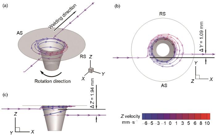
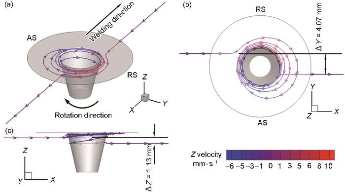
... 在FSW过程中,材料流动行为对焊缝缺陷的形成、微观组织的演变以及焊接接头的力学性能起着决定性作用[24,25],因此有必要详细讨论材料的流动模式.图9和10给出了Y = ± 2.5 mm、Z = 7 mm处(即靠近轴肩下方)附近的典型流线的多圈绕流路径及Z向速度分布.从图9b和10b可以看出,受轴肩影响,来自AS和RS的材料流入搅拌针高速流动区后,围绕搅拌针完成多个整圈绕流,材料在搅拌头前方绕行半径小,紧紧围绕搅拌针根部,材料在搅拌针后方,绕行半径逐步由大变小,最终均沉积在搅拌针后方AS.从图9c和10c可以看出,材料存在明显的垂向迁移行为,在搅拌针附近先向上迁移,再向下迁移,最终分别沉积在初始流入位置下方1.94 mm处(图9c)和1.13 mm处(图10c).总体而言,靠近轴肩的材料表现为明显的多圈绕流模式,这是由于该处的温度高,剪切阻力小,材料流动速率高,可充分驱动材料发生多圈绕流. ...
A review of friction stir welding of steels: Tool, material flow, microstructure, and properties
2
2018
... 数值模拟方法是一种获取FSW过程中材料流动和迁移行为的有效工具,主要分为计算固体力学(CSM)和计算流体力学(CFD)两种数值计算方法.基于CSM方法,将发生流动的材料视为塑性变形材料,通过任意Lagrange-Euler (ALE)方程或耦合Euler-Lagrange (CEL)方程预测材料的温度场、应力场、速度场和宏观界面形状等[25].基于CFD的热-力-流耦合模型能够全面揭示焊接过程中发生的复杂物理现象,并与实验结果相结合进行相互验证,从而为材料流动行为提供更深入的理解.在CFD数值计算方法中,主流的边界模型为速度边界模型和摩擦力边界模型.速度边界模型把滑移系数设为常值[17,19]或忽略了实际焊接过程中可能出现的滑移现象[16,20],导致搅拌头肩部外边缘材料流动速率过大或直接忽视与实验数据的对比.摩擦力边界模型减少了人为假设的因素,可实现工具-工件(T/W)界面接触状态的自适应转换[21,22,30,31],能够更加真实地反映材料流动行为,但需要建立准确的剪切应力条件[32].Liechty和Webb[18]对比了摩擦力边界模型与速度边界模型的模拟结果,认为采用摩擦力边界模型能更好地反映材料流动行为.Chen等[21]和Qiao等[33]建立了基于摩擦力边界的耦合模型,并预测得到水平面上的材料流动模式.Yang等[22]在此基础上准确预测了3 mm薄板材料的垂直流动行为,并定量分析了材料垂向流动的方向和移动距离. ...
... 在FSW过程中,材料流动行为对焊缝缺陷的形成、微观组织的演变以及焊接接头的力学性能起着决定性作用[24,25],因此有必要详细讨论材料的流动模式.图9和10给出了Y = ± 2.5 mm、Z = 7 mm处(即靠近轴肩下方)附近的典型流线的多圈绕流路径及Z向速度分布.从图9b和10b可以看出,受轴肩影响,来自AS和RS的材料流入搅拌针高速流动区后,围绕搅拌针完成多个整圈绕流,材料在搅拌头前方绕行半径小,紧紧围绕搅拌针根部,材料在搅拌针后方,绕行半径逐步由大变小,最终均沉积在搅拌针后方AS.从图9c和10c可以看出,材料存在明显的垂向迁移行为,在搅拌针附近先向上迁移,再向下迁移,最终分别沉积在初始流入位置下方1.94 mm处(图9c)和1.13 mm处(图10c).总体而言,靠近轴肩的材料表现为明显的多圈绕流模式,这是由于该处的温度高,剪切阻力小,材料流动速率高,可充分驱动材料发生多圈绕流. ...
Experimental evaluation of strain and strain rate during rapid cooling friction stir welding of pure copper
0
2019
Material flow velocity, strain and strain rate in ultrasonic vibration enhanced friction stir welding of dissimilar Al/Mg alloys
0
2022
Modeling and simulation of interface friction and material flow behavior during friction stir welding
1
2023
... 为探究FSW过程中材料流动-沉积行为,研究人员通过实验和数值模拟进行了广泛研究,包括示踪剂追踪技术[9~15]和数值计算方法[16~23],许多基于实验和模拟的研究揭示了材料在搅拌头周围表现出多圈绕流模式和直通流动模式[23~28].实验可视化研究主要通过引入与母材物性存在差异的材料作为标记物来实现,利用实验表征手段直接呈现材料流动过程[23,29].研究人员采用铜条[9]、钨球[10]、铜箔[12]、增厚氧化层[13]和异种焊丝[14]等材料作为标记物,追踪材料的流动轨迹和沉积位置.但是采用追踪材料的实验方法也存在一定的局限性.Schimdt等[9]通过焊缝中心纵向、焊缝横向位置设置0.1 mm厚铜条作为追踪材料,对FSW过程的试板进行计算机断层扫描(CT)分析,观察到追踪材料在轴肩部位呈“S”形或“C”形轨迹,并从材料流动速度和沉积位置,判断出材料在沉积前完成多次旋转,由于实验的局限性,无法定量给出某点追踪材料的流动轨迹和沉积位置.Morisada等[10]分别在A1050铝合金和低碳钢搅拌区焊缝中心预制孔中嵌入钨球,搅拌区±30°的位置放置了两组X射线透射系统,通过观察,钨示踪剂材料在铝合金焊缝搅拌头周围存在多圈绕流现象并有沿垂向方向的迁移,而钨示踪剂材料在低碳钢焊缝中直接绕过后退侧沉积在搅拌头后方,呈现出直通绕流模式,实验中,由于钨球嵌入的位置有限,无法全面反映整个焊接区域的材料流动行为.Huang等[12]和Zeng等[13]采用人工增厚氧化层和分层铜箔直接追踪材料水平流动和垂向流动过程的迁移行为,但是未有效获得三维流动模型.因而,目前FSW材料流动-沉积行为的实验表征研究主要集中在搅拌过程中的材料迁移机理,即焊缝宏观结构的形成,关于材料流动过程中三维空间下的流速、应变及应变速率等关键物理参量的实验表征研究仍严重不足[23,29],且缺乏对材料流经搅拌头复杂几何区域周围完整的轨迹认识. ...
搅拌摩擦焊界面摩擦及材料流动行为仿真
1
2023
... 为探究FSW过程中材料流动-沉积行为,研究人员通过实验和数值模拟进行了广泛研究,包括示踪剂追踪技术[9~15]和数值计算方法[16~23],许多基于实验和模拟的研究揭示了材料在搅拌头周围表现出多圈绕流模式和直通流动模式[23~28].实验可视化研究主要通过引入与母材物性存在差异的材料作为标记物来实现,利用实验表征手段直接呈现材料流动过程[23,29].研究人员采用铜条[9]、钨球[10]、铜箔[12]、增厚氧化层[13]和异种焊丝[14]等材料作为标记物,追踪材料的流动轨迹和沉积位置.但是采用追踪材料的实验方法也存在一定的局限性.Schimdt等[9]通过焊缝中心纵向、焊缝横向位置设置0.1 mm厚铜条作为追踪材料,对FSW过程的试板进行计算机断层扫描(CT)分析,观察到追踪材料在轴肩部位呈“S”形或“C”形轨迹,并从材料流动速度和沉积位置,判断出材料在沉积前完成多次旋转,由于实验的局限性,无法定量给出某点追踪材料的流动轨迹和沉积位置.Morisada等[10]分别在A1050铝合金和低碳钢搅拌区焊缝中心预制孔中嵌入钨球,搅拌区±30°的位置放置了两组X射线透射系统,通过观察,钨示踪剂材料在铝合金焊缝搅拌头周围存在多圈绕流现象并有沿垂向方向的迁移,而钨示踪剂材料在低碳钢焊缝中直接绕过后退侧沉积在搅拌头后方,呈现出直通绕流模式,实验中,由于钨球嵌入的位置有限,无法全面反映整个焊接区域的材料流动行为.Huang等[12]和Zeng等[13]采用人工增厚氧化层和分层铜箔直接追踪材料水平流动和垂向流动过程的迁移行为,但是未有效获得三维流动模型.因而,目前FSW材料流动-沉积行为的实验表征研究主要集中在搅拌过程中的材料迁移机理,即焊缝宏观结构的形成,关于材料流动过程中三维空间下的流速、应变及应变速率等关键物理参量的实验表征研究仍严重不足[23,29],且缺乏对材料流经搅拌头复杂几何区域周围完整的轨迹认识. ...
State-of-art of experimental characterization of material flow in friction stir welding
2
2020
... 为探究FSW过程中材料流动-沉积行为,研究人员通过实验和数值模拟进行了广泛研究,包括示踪剂追踪技术[9~15]和数值计算方法[16~23],许多基于实验和模拟的研究揭示了材料在搅拌头周围表现出多圈绕流模式和直通流动模式[23~28].实验可视化研究主要通过引入与母材物性存在差异的材料作为标记物来实现,利用实验表征手段直接呈现材料流动过程[23,29].研究人员采用铜条[9]、钨球[10]、铜箔[12]、增厚氧化层[13]和异种焊丝[14]等材料作为标记物,追踪材料的流动轨迹和沉积位置.但是采用追踪材料的实验方法也存在一定的局限性.Schimdt等[9]通过焊缝中心纵向、焊缝横向位置设置0.1 mm厚铜条作为追踪材料,对FSW过程的试板进行计算机断层扫描(CT)分析,观察到追踪材料在轴肩部位呈“S”形或“C”形轨迹,并从材料流动速度和沉积位置,判断出材料在沉积前完成多次旋转,由于实验的局限性,无法定量给出某点追踪材料的流动轨迹和沉积位置.Morisada等[10]分别在A1050铝合金和低碳钢搅拌区焊缝中心预制孔中嵌入钨球,搅拌区±30°的位置放置了两组X射线透射系统,通过观察,钨示踪剂材料在铝合金焊缝搅拌头周围存在多圈绕流现象并有沿垂向方向的迁移,而钨示踪剂材料在低碳钢焊缝中直接绕过后退侧沉积在搅拌头后方,呈现出直通绕流模式,实验中,由于钨球嵌入的位置有限,无法全面反映整个焊接区域的材料流动行为.Huang等[12]和Zeng等[13]采用人工增厚氧化层和分层铜箔直接追踪材料水平流动和垂向流动过程的迁移行为,但是未有效获得三维流动模型.因而,目前FSW材料流动-沉积行为的实验表征研究主要集中在搅拌过程中的材料迁移机理,即焊缝宏观结构的形成,关于材料流动过程中三维空间下的流速、应变及应变速率等关键物理参量的实验表征研究仍严重不足[23,29],且缺乏对材料流经搅拌头复杂几何区域周围完整的轨迹认识. ...
... ,29],且缺乏对材料流经搅拌头复杂几何区域周围完整的轨迹认识. ...
搅拌摩擦焊材料流动的试验表征研究现状
2
2020
... 为探究FSW过程中材料流动-沉积行为,研究人员通过实验和数值模拟进行了广泛研究,包括示踪剂追踪技术[9~15]和数值计算方法[16~23],许多基于实验和模拟的研究揭示了材料在搅拌头周围表现出多圈绕流模式和直通流动模式[23~28].实验可视化研究主要通过引入与母材物性存在差异的材料作为标记物来实现,利用实验表征手段直接呈现材料流动过程[23,29].研究人员采用铜条[9]、钨球[10]、铜箔[12]、增厚氧化层[13]和异种焊丝[14]等材料作为标记物,追踪材料的流动轨迹和沉积位置.但是采用追踪材料的实验方法也存在一定的局限性.Schimdt等[9]通过焊缝中心纵向、焊缝横向位置设置0.1 mm厚铜条作为追踪材料,对FSW过程的试板进行计算机断层扫描(CT)分析,观察到追踪材料在轴肩部位呈“S”形或“C”形轨迹,并从材料流动速度和沉积位置,判断出材料在沉积前完成多次旋转,由于实验的局限性,无法定量给出某点追踪材料的流动轨迹和沉积位置.Morisada等[10]分别在A1050铝合金和低碳钢搅拌区焊缝中心预制孔中嵌入钨球,搅拌区±30°的位置放置了两组X射线透射系统,通过观察,钨示踪剂材料在铝合金焊缝搅拌头周围存在多圈绕流现象并有沿垂向方向的迁移,而钨示踪剂材料在低碳钢焊缝中直接绕过后退侧沉积在搅拌头后方,呈现出直通绕流模式,实验中,由于钨球嵌入的位置有限,无法全面反映整个焊接区域的材料流动行为.Huang等[12]和Zeng等[13]采用人工增厚氧化层和分层铜箔直接追踪材料水平流动和垂向流动过程的迁移行为,但是未有效获得三维流动模型.因而,目前FSW材料流动-沉积行为的实验表征研究主要集中在搅拌过程中的材料迁移机理,即焊缝宏观结构的形成,关于材料流动过程中三维空间下的流速、应变及应变速率等关键物理参量的实验表征研究仍严重不足[23,29],且缺乏对材料流经搅拌头复杂几何区域周围完整的轨迹认识. ...
... ,29],且缺乏对材料流经搅拌头复杂几何区域周围完整的轨迹认识. ...
Tool-workpiece stick-slip conditions and their effects on torque and heat generation rate in the friction stir welding
1
2021
... 数值模拟方法是一种获取FSW过程中材料流动和迁移行为的有效工具,主要分为计算固体力学(CSM)和计算流体力学(CFD)两种数值计算方法.基于CSM方法,将发生流动的材料视为塑性变形材料,通过任意Lagrange-Euler (ALE)方程或耦合Euler-Lagrange (CEL)方程预测材料的温度场、应力场、速度场和宏观界面形状等[25].基于CFD的热-力-流耦合模型能够全面揭示焊接过程中发生的复杂物理现象,并与实验结果相结合进行相互验证,从而为材料流动行为提供更深入的理解.在CFD数值计算方法中,主流的边界模型为速度边界模型和摩擦力边界模型.速度边界模型把滑移系数设为常值[17,19]或忽略了实际焊接过程中可能出现的滑移现象[16,20],导致搅拌头肩部外边缘材料流动速率过大或直接忽视与实验数据的对比.摩擦力边界模型减少了人为假设的因素,可实现工具-工件(T/W)界面接触状态的自适应转换[21,22,30,31],能够更加真实地反映材料流动行为,但需要建立准确的剪切应力条件[32].Liechty和Webb[18]对比了摩擦力边界模型与速度边界模型的模拟结果,认为采用摩擦力边界模型能更好地反映材料流动行为.Chen等[21]和Qiao等[33]建立了基于摩擦力边界的耦合模型,并预测得到水平面上的材料流动模式.Yang等[22]在此基础上准确预测了3 mm薄板材料的垂直流动行为,并定量分析了材料垂向流动的方向和移动距离. ...
Flow-coupled thermo-mechanical analysis of frictional behaviors at the tool-workpiece interface during friction stir welding
1
2022
... 数值模拟方法是一种获取FSW过程中材料流动和迁移行为的有效工具,主要分为计算固体力学(CSM)和计算流体力学(CFD)两种数值计算方法.基于CSM方法,将发生流动的材料视为塑性变形材料,通过任意Lagrange-Euler (ALE)方程或耦合Euler-Lagrange (CEL)方程预测材料的温度场、应力场、速度场和宏观界面形状等[25].基于CFD的热-力-流耦合模型能够全面揭示焊接过程中发生的复杂物理现象,并与实验结果相结合进行相互验证,从而为材料流动行为提供更深入的理解.在CFD数值计算方法中,主流的边界模型为速度边界模型和摩擦力边界模型.速度边界模型把滑移系数设为常值[17,19]或忽略了实际焊接过程中可能出现的滑移现象[16,20],导致搅拌头肩部外边缘材料流动速率过大或直接忽视与实验数据的对比.摩擦力边界模型减少了人为假设的因素,可实现工具-工件(T/W)界面接触状态的自适应转换[21,22,30,31],能够更加真实地反映材料流动行为,但需要建立准确的剪切应力条件[32].Liechty和Webb[18]对比了摩擦力边界模型与速度边界模型的模拟结果,认为采用摩擦力边界模型能更好地反映材料流动行为.Chen等[21]和Qiao等[33]建立了基于摩擦力边界的耦合模型,并预测得到水平面上的材料流动模式.Yang等[22]在此基础上准确预测了3 mm薄板材料的垂直流动行为,并定量分析了材料垂向流动的方向和移动距离. ...
A novel method of lateral tool-tilt for optimizing material flow and temperature distribution in friction stir welding
1
2024
... 数值模拟方法是一种获取FSW过程中材料流动和迁移行为的有效工具,主要分为计算固体力学(CSM)和计算流体力学(CFD)两种数值计算方法.基于CSM方法,将发生流动的材料视为塑性变形材料,通过任意Lagrange-Euler (ALE)方程或耦合Euler-Lagrange (CEL)方程预测材料的温度场、应力场、速度场和宏观界面形状等[25].基于CFD的热-力-流耦合模型能够全面揭示焊接过程中发生的复杂物理现象,并与实验结果相结合进行相互验证,从而为材料流动行为提供更深入的理解.在CFD数值计算方法中,主流的边界模型为速度边界模型和摩擦力边界模型.速度边界模型把滑移系数设为常值[17,19]或忽略了实际焊接过程中可能出现的滑移现象[16,20],导致搅拌头肩部外边缘材料流动速率过大或直接忽视与实验数据的对比.摩擦力边界模型减少了人为假设的因素,可实现工具-工件(T/W)界面接触状态的自适应转换[21,22,30,31],能够更加真实地反映材料流动行为,但需要建立准确的剪切应力条件[32].Liechty和Webb[18]对比了摩擦力边界模型与速度边界模型的模拟结果,认为采用摩擦力边界模型能更好地反映材料流动行为.Chen等[21]和Qiao等[33]建立了基于摩擦力边界的耦合模型,并预测得到水平面上的材料流动模式.Yang等[22]在此基础上准确预测了3 mm薄板材料的垂直流动行为,并定量分析了材料垂向流动的方向和移动距离. ...
Elucidation of solid-state metal flow behaviors during friction stir welding: Numerical and experimental investigation
1
2023
... 数值模拟方法是一种获取FSW过程中材料流动和迁移行为的有效工具,主要分为计算固体力学(CSM)和计算流体力学(CFD)两种数值计算方法.基于CSM方法,将发生流动的材料视为塑性变形材料,通过任意Lagrange-Euler (ALE)方程或耦合Euler-Lagrange (CEL)方程预测材料的温度场、应力场、速度场和宏观界面形状等[25].基于CFD的热-力-流耦合模型能够全面揭示焊接过程中发生的复杂物理现象,并与实验结果相结合进行相互验证,从而为材料流动行为提供更深入的理解.在CFD数值计算方法中,主流的边界模型为速度边界模型和摩擦力边界模型.速度边界模型把滑移系数设为常值[17,19]或忽略了实际焊接过程中可能出现的滑移现象[16,20],导致搅拌头肩部外边缘材料流动速率过大或直接忽视与实验数据的对比.摩擦力边界模型减少了人为假设的因素,可实现工具-工件(T/W)界面接触状态的自适应转换[21,22,30,31],能够更加真实地反映材料流动行为,但需要建立准确的剪切应力条件[32].Liechty和Webb[18]对比了摩擦力边界模型与速度边界模型的模拟结果,认为采用摩擦力边界模型能更好地反映材料流动行为.Chen等[21]和Qiao等[33]建立了基于摩擦力边界的耦合模型,并预测得到水平面上的材料流动模式.Yang等[22]在此基础上准确预测了3 mm薄板材料的垂直流动行为,并定量分析了材料垂向流动的方向和移动距离. ...
Modelling of entire friction stir welding process by explicit finite element method
2
2012
... 本工作采用基于计算流体力学的热-力-流全耦合数值模型,用于模拟2219-T87的焊接过程,几何模型如图2所示.网格划分采用六面体网格,总网格数量为619208个,节点数为651251个.在搅拌头与工件界面及其附近区域,采用更精细的网格划分,其最小尺寸约为0.1 mm,该网格质量确保了计算的收敛性,并能够准确表征材料的剧烈流动行为.在模型中,忽略搅拌头倾斜角度及下压量引起的几何变化,搅拌头在模型中的位置保持固定.热边界条件设置如下:“材料入口”和“材料出口”处的温度均设定为27 ℃,工件与侧壁及垫板的接触传热系数为500 W/(m2·K),工件上表面与空气之间的对流传热系数为50 W/(m2·K)[21,34,35].工件材料的密度()为2840 kg/m³;比热容()、热导率(λ)的取值参考文献[36,37].数值模型采用商业软件ANSYS Fluent进行求解. ...
... 将搅拌头施加在工件上产生的摩擦剪应力()表达式为[21, 34]: ...
Influence of frictional heat spread pattern on the formation of intermetallic layers at the dissimilar FSW joint interface between AA 5083 and HSLA steel
1
2022
... 本工作采用基于计算流体力学的热-力-流全耦合数值模型,用于模拟2219-T87的焊接过程,几何模型如图2所示.网格划分采用六面体网格,总网格数量为619208个,节点数为651251个.在搅拌头与工件界面及其附近区域,采用更精细的网格划分,其最小尺寸约为0.1 mm,该网格质量确保了计算的收敛性,并能够准确表征材料的剧烈流动行为.在模型中,忽略搅拌头倾斜角度及下压量引起的几何变化,搅拌头在模型中的位置保持固定.热边界条件设置如下:“材料入口”和“材料出口”处的温度均设定为27 ℃,工件与侧壁及垫板的接触传热系数为500 W/(m2·K),工件上表面与空气之间的对流传热系数为50 W/(m2·K)[21,34,35].工件材料的密度()为2840 kg/m³;比热容()、热导率(λ)的取值参考文献[36,37].数值模型采用商业软件ANSYS Fluent进行求解. ...
Numerical simulation of thermal field of friction stir welded 2219 aluminum alloy thick plate
1
2010
... 本工作采用基于计算流体力学的热-力-流全耦合数值模型,用于模拟2219-T87的焊接过程,几何模型如图2所示.网格划分采用六面体网格,总网格数量为619208个,节点数为651251个.在搅拌头与工件界面及其附近区域,采用更精细的网格划分,其最小尺寸约为0.1 mm,该网格质量确保了计算的收敛性,并能够准确表征材料的剧烈流动行为.在模型中,忽略搅拌头倾斜角度及下压量引起的几何变化,搅拌头在模型中的位置保持固定.热边界条件设置如下:“材料入口”和“材料出口”处的温度均设定为27 ℃,工件与侧壁及垫板的接触传热系数为500 W/(m2·K),工件上表面与空气之间的对流传热系数为50 W/(m2·K)[21,34,35].工件材料的密度()为2840 kg/m³;比热容()、热导率(λ)的取值参考文献[36,37].数值模型采用商业软件ANSYS Fluent进行求解. ...
2219铝合金厚板搅拌摩擦焊接温度场数值模拟
1
2010
... 本工作采用基于计算流体力学的热-力-流全耦合数值模型,用于模拟2219-T87的焊接过程,几何模型如图2所示.网格划分采用六面体网格,总网格数量为619208个,节点数为651251个.在搅拌头与工件界面及其附近区域,采用更精细的网格划分,其最小尺寸约为0.1 mm,该网格质量确保了计算的收敛性,并能够准确表征材料的剧烈流动行为.在模型中,忽略搅拌头倾斜角度及下压量引起的几何变化,搅拌头在模型中的位置保持固定.热边界条件设置如下:“材料入口”和“材料出口”处的温度均设定为27 ℃,工件与侧壁及垫板的接触传热系数为500 W/(m2·K),工件上表面与空气之间的对流传热系数为50 W/(m2·K)[21,34,35].工件材料的密度()为2840 kg/m³;比热容()、热导率(λ)的取值参考文献[36,37].数值模型采用商业软件ANSYS Fluent进行求解. ...
Thermal mechanical coupling simulation of temperature and residual stress in friction stir welding of 2219 aluminum alloy
1
2019
... 本工作采用基于计算流体力学的热-力-流全耦合数值模型,用于模拟2219-T87的焊接过程,几何模型如图2所示.网格划分采用六面体网格,总网格数量为619208个,节点数为651251个.在搅拌头与工件界面及其附近区域,采用更精细的网格划分,其最小尺寸约为0.1 mm,该网格质量确保了计算的收敛性,并能够准确表征材料的剧烈流动行为.在模型中,忽略搅拌头倾斜角度及下压量引起的几何变化,搅拌头在模型中的位置保持固定.热边界条件设置如下:“材料入口”和“材料出口”处的温度均设定为27 ℃,工件与侧壁及垫板的接触传热系数为500 W/(m2·K),工件上表面与空气之间的对流传热系数为50 W/(m2·K)[21,34,35].工件材料的密度()为2840 kg/m³;比热容()、热导率(λ)的取值参考文献[36,37].数值模型采用商业软件ANSYS Fluent进行求解. ...
2219铝合金搅拌摩擦焊温度与残余应力热力耦合模拟
1
2019
... 本工作采用基于计算流体力学的热-力-流全耦合数值模型,用于模拟2219-T87的焊接过程,几何模型如图2所示.网格划分采用六面体网格,总网格数量为619208个,节点数为651251个.在搅拌头与工件界面及其附近区域,采用更精细的网格划分,其最小尺寸约为0.1 mm,该网格质量确保了计算的收敛性,并能够准确表征材料的剧烈流动行为.在模型中,忽略搅拌头倾斜角度及下压量引起的几何变化,搅拌头在模型中的位置保持固定.热边界条件设置如下:“材料入口”和“材料出口”处的温度均设定为27 ℃,工件与侧壁及垫板的接触传热系数为500 W/(m2·K),工件上表面与空气之间的对流传热系数为50 W/(m2·K)[21,34,35].工件材料的密度()为2840 kg/m³;比热容()、热导率(λ)的取值参考文献[36,37].数值模型采用商业软件ANSYS Fluent进行求解. ...
Sucking-extruding theory for the material flow in friction stir welds
1
2009
... 式中,为Coulomb摩擦系数,参考文献[21,22],在本工作计算中取0.33;为T/W界面上的法向压强;为界面相对速度,可以表达为,、分别为界面上搅拌头速度和工件速度;为控制因子,取值50 s/m[21].在FSW过程中,搅拌针螺纹对材料流动具有重要影响:一方面,螺纹表面与塑性变形区之间的摩擦力驱动螺纹槽内材料作圆周运动;另一方面,搅拌头旋转前进时垂直于螺纹表面的压力推动材料产生垂直方向运动[38,39].在本模型中,搅拌针螺纹界面速度()可以表达成和螺纹旋转产生的附加垂向速度()的矢量和: ...
搅拌摩擦焊焊缝金属塑性流动的抽吸-挤压理论
1
2009
... 式中,为Coulomb摩擦系数,参考文献[21,22],在本工作计算中取0.33;为T/W界面上的法向压强;为界面相对速度,可以表达为,、分别为界面上搅拌头速度和工件速度;为控制因子,取值50 s/m[21].在FSW过程中,搅拌针螺纹对材料流动具有重要影响:一方面,螺纹表面与塑性变形区之间的摩擦力驱动螺纹槽内材料作圆周运动;另一方面,搅拌头旋转前进时垂直于螺纹表面的压力推动材料产生垂直方向运动[38,39].在本模型中,搅拌针螺纹界面速度()可以表达成和螺纹旋转产生的附加垂向速度()的矢量和: ...
Effect of axial ultrasonic vibration on metal flow behavior during friction stir welding
1
2021
... 式中,为Coulomb摩擦系数,参考文献[21,22],在本工作计算中取0.33;为T/W界面上的法向压强;为界面相对速度,可以表达为,、分别为界面上搅拌头速度和工件速度;为控制因子,取值50 s/m[21].在FSW过程中,搅拌针螺纹对材料流动具有重要影响:一方面,螺纹表面与塑性变形区之间的摩擦力驱动螺纹槽内材料作圆周运动;另一方面,搅拌头旋转前进时垂直于螺纹表面的压力推动材料产生垂直方向运动[38,39].在本模型中,搅拌针螺纹界面速度()可以表达成和螺纹旋转产生的附加垂向速度()的矢量和: ...
轴向超声振动对搅拌摩擦焊过程中金属流动行为的影响
1
2021
... 式中,为Coulomb摩擦系数,参考文献[21,22],在本工作计算中取0.33;为T/W界面上的法向压强;为界面相对速度,可以表达为,、分别为界面上搅拌头速度和工件速度;为控制因子,取值50 s/m[21].在FSW过程中,搅拌针螺纹对材料流动具有重要影响:一方面,螺纹表面与塑性变形区之间的摩擦力驱动螺纹槽内材料作圆周运动;另一方面,搅拌头旋转前进时垂直于螺纹表面的压力推动材料产生垂直方向运动[38,39].在本模型中,搅拌针螺纹界面速度()可以表达成和螺纹旋转产生的附加垂向速度()的矢量和: ...
A study on the variation of forces and temperature in a friction stir welding process: A finite element approach
1
2016
... 为了准确描述流体的流动特性,将流体的黏度表示为流动应力与应变(ε)、等效应变速率及温度的函数[16,40]: ...
Flow stress of 2219 aluminium alloy during hot compression deformation
1
2008
... 式(12)~(15)中,为材料应力水平参数,取值50 MPa;为Zener-Hollomon参数;为应变速率张量的分量;R为理想气体常数,取值8.314 J/(mol·K);Q为热变形激活能,取值153300 J/mol;n为应力指数,取值6.91;A为结构因数,取值2.65 × 1010 s-1 [41];、为三维空间中的速度矢量分量,、为三维空间中的位置.材料的固相线温度为543 ℃[42,43],在模拟过程中采用经验软化法[44~47],修正固相线软化区域的流变应力. ...
2219铝合金热压缩变形流变应力
1
2008
... 式(12)~(15)中,为材料应力水平参数,取值50 MPa;为Zener-Hollomon参数;为应变速率张量的分量;R为理想气体常数,取值8.314 J/(mol·K);Q为热变形激活能,取值153300 J/mol;n为应力指数,取值6.91;A为结构因数,取值2.65 × 1010 s-1 [41];、为三维空间中的速度矢量分量,、为三维空间中的位置.材料的固相线温度为543 ℃[42,43],在模拟过程中采用经验软化法[44~47],修正固相线软化区域的流变应力. ...
1
2000
... 式(12)~(15)中,为材料应力水平参数,取值50 MPa;为Zener-Hollomon参数;为应变速率张量的分量;R为理想气体常数,取值8.314 J/(mol·K);Q为热变形激活能,取值153300 J/mol;n为应力指数,取值6.91;A为结构因数,取值2.65 × 1010 s-1 [41];、为三维空间中的速度矢量分量,、为三维空间中的位置.材料的固相线温度为543 ℃[42,43],在模拟过程中采用经验软化法[44~47],修正固相线软化区域的流变应力. ...
1
2000
... 式(12)~(15)中,为材料应力水平参数,取值50 MPa;为Zener-Hollomon参数;为应变速率张量的分量;R为理想气体常数,取值8.314 J/(mol·K);Q为热变形激活能,取值153300 J/mol;n为应力指数,取值6.91;A为结构因数,取值2.65 × 1010 s-1 [41];、为三维空间中的速度矢量分量,、为三维空间中的位置.材料的固相线温度为543 ℃[42,43],在模拟过程中采用经验软化法[44~47],修正固相线软化区域的流变应力. ...
1
1993
... 式(12)~(15)中,为材料应力水平参数,取值50 MPa;为Zener-Hollomon参数;为应变速率张量的分量;R为理想气体常数,取值8.314 J/(mol·K);Q为热变形激活能,取值153300 J/mol;n为应力指数,取值6.91;A为结构因数,取值2.65 × 1010 s-1 [41];、为三维空间中的速度矢量分量,、为三维空间中的位置.材料的固相线温度为543 ℃[42,43],在模拟过程中采用经验软化法[44~47],修正固相线软化区域的流变应力. ...
CFD modelling of friction stir welding of thick plate 7449 aluminium alloy
1
2006
... 式(12)~(15)中,为材料应力水平参数,取值50 MPa;为Zener-Hollomon参数;为应变速率张量的分量;R为理想气体常数,取值8.314 J/(mol·K);Q为热变形激活能,取值153300 J/mol;n为应力指数,取值6.91;A为结构因数,取值2.65 × 1010 s-1 [41];、为三维空间中的速度矢量分量,、为三维空间中的位置.材料的固相线温度为543 ℃[42,43],在模拟过程中采用经验软化法[44~47],修正固相线软化区域的流变应力. ...
Numerical modeling for the effect of pin profiles on thermal and material flow characteristics in friction stir welding
0
2015
Three-dimensional thermal-mechanical analysis of retractable pin tool friction stir welding process
0
2019
Improved analytical model for thermal softening in aluminum alloys form room temperature to solidus
1
2023
... 式(12)~(15)中,为材料应力水平参数,取值50 MPa;为Zener-Hollomon参数;为应变速率张量的分量;R为理想气体常数,取值8.314 J/(mol·K);Q为热变形激活能,取值153300 J/mol;n为应力指数,取值6.91;A为结构因数,取值2.65 × 1010 s-1 [41];、为三维空间中的速度矢量分量,、为三维空间中的位置.材料的固相线温度为543 ℃[42,43],在模拟过程中采用经验软化法[44~47],修正固相线软化区域的流变应力. ...