


在高温高压水汽环境腐蚀条件下,锆合金将出现均匀腐蚀增重。腐蚀过程中,合金表面将形成致密柱状晶氧化物,使腐蚀增重呈抛物线或立方关系(即钝化过程)。当氧化膜厚度达到2~3 μm时,氧化膜由于内应力等因素导致其失去致密性,氧化膜中产生大量连通裂纹,使腐蚀介质得以无阻碍地到达氧化膜/金属(O/M)界面,使腐蚀速率快速增加,即发生腐蚀转折(transition)[1,2]。尽管有研究[3,4]报道了合金元素、加工工艺、热处理工艺对腐蚀行为的影响,但目前仍不清楚氧化膜内是何种因素导致转折发生。Likhanskii和Evdokimov[5]发现O/M界面的波动起伏对氧化膜完整性造成影响,氧化膜中内应力聚集被认为是导致转折的主要原因[6,7];Preuss等[8]认为,氧化时形成的亚稳四方ZrO2 (t-ZrO2)在转折时的不稳定相变将引起转折,但该观点仍缺乏直接证据。此外,虽然文献中广泛报道了锆合金在长期腐蚀时存在周期性的钝化-转折氧化规律[2],但仅针对初次转折前后的腐蚀行为开展了深入分析[9,10],而在初次转折后,长期腐蚀过程中的氧化组织演变规律却少有报道,这制约了对锆合金腐蚀行为的全面理解。
1 实验方法
实验采用了2种新型锆合金包壳管材材料,分别为低Nb含量的Zr-0.5Sn-0.15Nb-0.5Fe-0.25V合金(质量分数,%,下同) (N2合金),以及高Nb含量的Zr-0.2Sn-1.3Nb-0.1Fe-0.05V合金(N3合金)。有研究[13]表明,锆合金中微量V元素的添加有利于提高其耐腐蚀性能。国际上,部分耐高燃耗腐蚀的新型锆合金中同样添加了V元素,这反映出V元素对锆合金耐腐蚀性能的有利性[1]。本工作所用包壳材料的制备工艺、合金组织及第二相成分参考文献[11],2种合金均为完全再结晶组织,晶粒平均尺寸约2 μm,第二相平均尺寸约90 nm,第二相在合金中均匀分布。2种合金固溶元素量有较大不同,第二相成分、结构差异较大。
依据ASTM G2M—006标准,在容量为5 L的316不锈钢静态高压釜中进行腐蚀实验。腐蚀样品尺寸为外径9.6 mm、壁厚0.57 mm、长度50 mm的包壳管材,样品表面经30%H2O + 30%HNO3 + 30%H2SO4 + 10%HF (体积分数)溶液酸洗,表面光亮。腐蚀条件为400℃、10.3 MPa除氧过热蒸汽,除氧方法为在140℃时热力除氧。腐蚀时间长达800 d,腐蚀过程中密集取样。
对腐蚀不同时间后的样品进行分析,包括氧化膜截面、内表面形貌以及t-ZrO2等效厚度、O空位浓度。氧化膜截面样品制备方法为:采用树脂热镶,进行精细研磨,随后进行长时间小幅度振动抛光获得光亮平整截面。使用Nano400扫描电子显微镜(SEM)观察氧化膜截面形貌。氧化膜截面薄膜样品采用超高精密聚焦离子束(FIB)切割获得,所用设备为双束系统FIB NB5000,制备方法为:首先在样品表面涂覆一层Pt,以保护合金表面氧化膜;然后利用离子束在涂层的两边打出2个凹坑,使中间留下1 μm左右厚的薄膜;接着利用Pt喷涂以及离子束切割将遗留的区域从样品中取出;最后用一系列离子束流精密抛光试样表面,并使其厚度减薄至100 nm以下。采用Tecnai G2 F30透射电子显微镜(TEM)对氧化膜薄膜样品进行观察。
暴露O/M界面的氧化膜内表面样品制备方法为:将腐蚀样品浸泡于45%H2O + 45%HNO3 + 10%HF (体积分数)中若干时间,通过酸洗去除金属基体;随后将不溶于酸溶液的氧化膜沿内表面朝外粘贴。首先利用Nano400 SEM观察O/M界面;其次,利用LEXT OLS4000共聚焦激光扫描显微镜(CLSM)测量内表面氧化膜样品的三维形貌(CLSM横向分辨率约为100 nm,高度方向分辨率可达10 nm),并分析界面起伏强度(均方根斜率)。使用Invia激光共聚焦Raman光谱仪测试了内表面样品氧化物相,测试激光波长为514 nm,各样品分别测试至少10个点以统计物相特征的平均值。
2 实验结果及分析
2.1 腐蚀动力学
图1
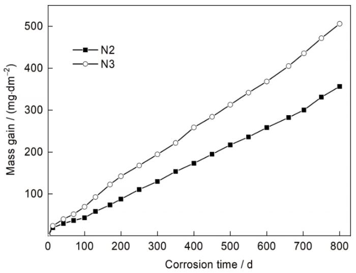
图1
Zr-0.5Sn-0.15Nb-0.5Fe-0.25V (N2)和Zr-0.2Sn-1.3Nb-0.1Fe-0.05V (N3)合金在400℃、10.3 MPa高温蒸汽中的腐蚀增重曲线
Fig.1
Mass gain curves of Zr-0.5Sn-0.15Nb-0.5Fe-0.25V (N2) and Zr-0.2Sn-1.3Nb-0.1Fe-0.05V (N3) alloys corroded in 400oC and 10.3 MPa steam
表1 腐蚀动力学关系拟合结果
Table 1
| Alloy | tdx d | Mass gain at transition point mg·dm-2 | Kinetics law in the pre-transition | Quasi-linear relationship in the post-transition |
|---|---|---|---|---|
| N2 | 130 | 45.04 | 6.76t0.42 | 0.44t - 0.26 |
| N3 | 80 | 51.75 | 7.19t0.46 | 0.60t + 16.30 |
2.2 氧化膜组织形貌演变
N2合金腐蚀不同时间后的氧化膜截面形貌的SEM像如图2所示。以腐蚀状态参数反映腐蚀所处阶段,其计算方法如下式:
式中,Tx 为合金腐蚀状态参数,x = 2时代表N2合金腐蚀状态参数,x = 3时代表N3合金腐蚀状态参数;t为腐蚀时间。根据周期性钝化-转折规律可以得到,当0 < Tx < 1时,腐蚀处于初次转折前的钝化阶段;当1 ≤ Tx < 2时,腐蚀处于初次转折后的再钝化阶段;当n - 1 ≤ Tx < n时(n为大于2的整数),腐蚀处于第n - 1次转折后、第n次转折前的再钝化阶段。N2合金转折时间为td2 = 130 d,腐蚀120 d时,T2 = 120 d / 130 d = 0.92,表明处于转折发生前;腐蚀200 d时,T2 = 1.54,表明处于初次转折后的再钝化阶段。从图2可见,转折前,N2合金氧化膜完整性较好,仅局部存在孤立横向裂纹(图2a~c);但转折后出现平行于界面的缺陷带(defect band) (图2d和e),导致氧化膜致密性丧失。缺陷带的出现标志了转折的发生[14]。O/M界面始终存在形似正弦函数的起伏波动,且容易在O/M界面的金属凸起位置发现横向裂纹。
图2

图2
N2合金腐蚀不同时间后氧化膜截面形貌的SEM像
Fig.2
Cross-section SEM images of N2 alloy corroded for 40 d (T2 = 0.31) (a), 80 d (T2 = 0.62) (b), 120 d (T2 = 0.92) (c), 160 d (T2 = 1.23) (d), and 200 d (T2 = 1.54) (e) (T2 is the corrosion state parameter of N2 alloy. T2 = 0.92 indicates that corrosion is in pre-transition stage, and T2 = 1.54 indicates that corrosion is in re-densification stage after primary transition)
图3
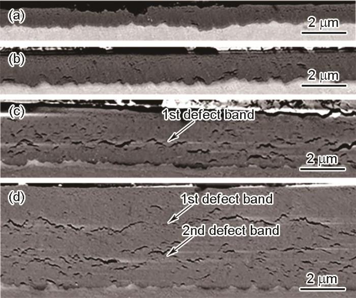
图3
N3合金腐蚀不同时间后氧化膜截面形貌的SEM像
Fig.3
Cross-section SEM images of N3 alloy corroded for 20 d (T3 = 0.25) (a), 60 d (T3 = 0.75) (b), 100 d (T3 = 1.25) (c), and 200 d (T3 = 2.50) (d) (T3 is the corrosion state parameter of N3 alloy. T3 = 1.25 indicates that corrosion is in re-densification stage after primary transition, and T3 = 2.50 indicates that corrosion is in re-densification stage after secondary transition)
图4
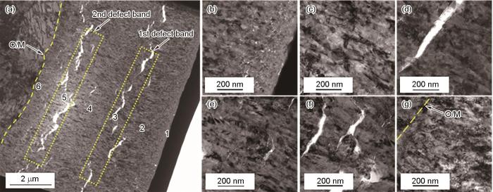
图4
N3合金腐蚀200 d后氧化膜的TEM像
Fig.4
TEM images of oxide foil of N3 alloy corroded for 200 d (a) and locally magnified images of areas 1 (b), 2 (c), 3 (d), 4 (e), 5 (f), and 6 (g) in Fig.4a (O/M—oxide film/metal)
图5
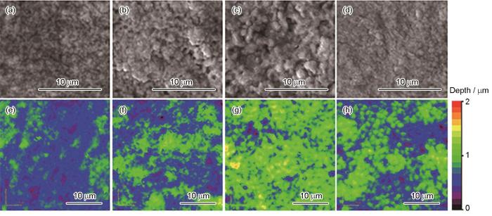
图5
N2合金腐蚀不同时间后氧化膜内表面SEM像和CLSM三维形貌像
Fig.5
SEM images (a-d) and CLSM 3D images (e-h) of inner-face of N2 alloy corroded for 20 d (T2 = 0.15) (a, e), 60 d (T2 = 0.46) (b, f), 120 d (T2 = 0.92) (c, g), and 140 d (T2 = 1.08) (d, h)
式中,z(x, y)为起伏高度在横向的分布函数,A为测试内表面面积。
平均起伏强度随时间的演变关系如图6所示。可见,在转折前,起伏强度随时间增加而增大,转折后显著减小;2种合金起伏强度最大临界值相近,均为0.25;N3合金界面起伏演变明显快于N2合金,这与2种合金转折时间相对应;初次转折后的再钝化阶段,起伏强度再次随时间增加而增大,第二次转折时再次减小。以上结果表明,内表面形貌的演变满足周期演变规律。N3合金在第二次转折后Sdq数据规律性较差,这是由于不同样品长期腐蚀后腐蚀状态的差异性增大。
图6

图6
N2和N3合金腐蚀氧化膜/金属界面的起伏强度随时间的演变
Fig.6
Evolutions of undulation intensity (Sdq) versus corrosion time of the O/M interface of N2 and N3 alloys
导致锆合金O/M界面粗糙起伏的根本原因是合金腐蚀速率的不均匀起伏,腐蚀速率的不均匀起伏主要与材料晶粒取向、化学成分的不均匀起伏以及缺陷分布等因素相关[12]。另外,局部过大的起伏振幅/波长比易导致界面氧化膜内产生横向裂纹,研究[12]表明,开裂原因可能为该部位应力聚集或四方相相变。转折的发生与孤立裂纹及连通裂纹的产生存在密切关系[15]。随界面波动起伏强度增加,不断在局部产生孤立横向裂纹;在转折发生时,起伏强度达到最大临界值,孤立横向裂纹逐渐相互连接形成连通横向裂纹,构成腐蚀介质渗透的重要通道。O/M界面起伏强度周期性达到临界状态,可能是转折周期性发生的部分原因。由于微区应力大小与界面起伏密切相关[16],因此界面微观起伏的周期性也反映了微观区域应力变化的周期性规律。该结论与锆合金氧化膜宏观应力演变规律并不相同,宏观上,应力随膜厚的增加逐渐降低[17]。
2.3 O/M界面t-ZrO2 演变
转折时,缺陷带中不仅产生了较大的连通裂纹,还产生了大量细密多孔等轴晶缺陷。由于起伏导致的氧化膜开裂主要为平行于O/M界面的横向裂纹[12],多孔等轴晶缺陷主要由其他因素导致。Zr与水腐蚀反应生成大量亚稳氧化相[18],其中t-ZrO2最为重要,t-ZrO2→单斜ZrO2 (m-ZrO2)相变易产生等轴晶[19],且t-ZrO2相变也是转折发生的重要原因,因此利用Raman光谱对内表面氧化膜样品进行了物相分析,图7所示为N2和N3合金在过热蒸汽下腐蚀不同时间的内表面Raman光谱。其中,280 cm-1代表t-ZrO2特征峰位,178及192 cm-1代表m-ZrO2峰位。压应力以及O空位是O/M界面t-ZrO2的稳定剂[12],测试结果表明,即便基体溶解导致氧化膜中的宏观压应力大量释放,t-ZrO2在基体溶解后仍稳定存在,这与前期工作结果[20]一致。
图7

图7
N2及N3合金内表面Raman 光谱
Fig.7
Raman spectra of inner face of N2 (a) and N3 (b) alloys
利用下式计算t-ZrO2体积分数(ftet)[8]:
式中,It(280)为t-ZrO2的280 cm-1峰强度,Im(178)和Im(192)分别为m-ZrO2的178和192 cm-1峰强度。t-ZrO2含量近似反映了激光探测区域内的t-ZrO2体积分数,且由于t-ZrO2主要分布在O/M界面,则界面t-ZrO2等效厚度(d
式中,d0为激光穿透有效厚度。当激光入射深度大于氧化膜厚度时,d0取为氧化膜厚度;当激光入射深度小于氧化膜厚度时,d0取为激光入射深度。内表面样品测试时,514 nm波长激光在ZrO2膜层中的入射深度约为1.5 μm[20]。
根据以上计算方法,分析了N2和N3合金氧化膜中t-ZrO2等效厚度随腐蚀状态参数的变化规律,如图8a所示。转折前,随时间增加,t-ZrO2等效厚度逐渐增加;直至转折时,t-ZrO2厚度达到临界尺寸而陡降,这暗示了t-ZrO2→m-ZrO2相变的发生;第二次钝化-转折时,t-ZrO2等效厚度演变规律与第一次相同,t-ZrO2生长与腐蚀状态参数对应。结果表明,与起伏强度演变规律相同,O/M界面t-ZrO2等效厚度同样周期性达到临界状态,这是转折周期性发生的重要原因之一。
图8
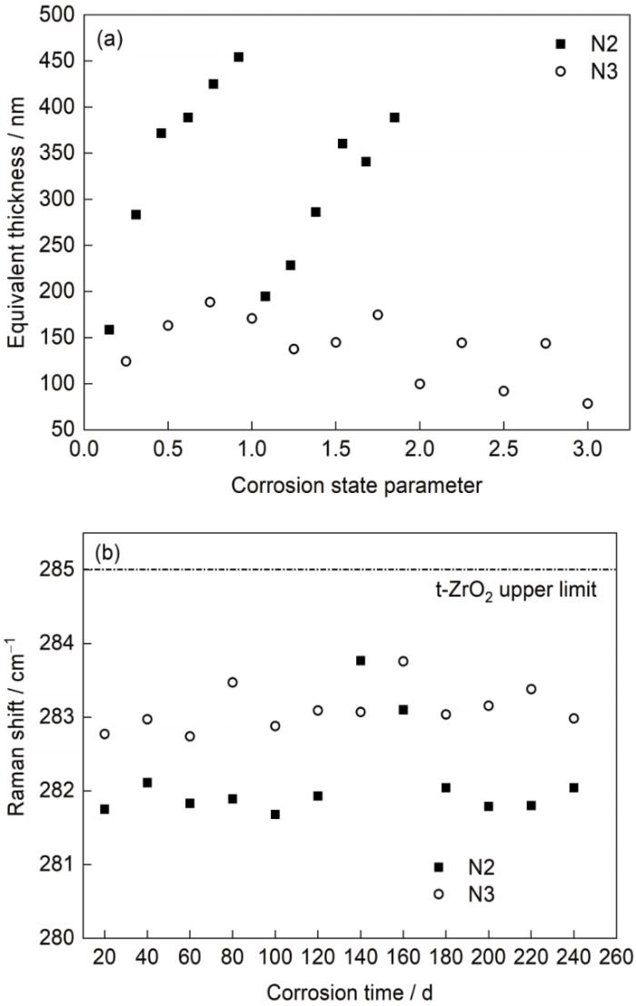
图8
t-ZrO2等效厚度随腐蚀状态参数的变化规律及内表面t-ZrO2特征峰位随腐蚀时间演变
Fig.8
Evolutions of equivalent tetragonal thickness versus corrosion stage parameter (a) and t-ZrO2 peaks versus corrosion time (b)
N2合金t-ZrO2最大临界厚度为450 nm左右,而N3合金临界厚度仅为200 nm左右,N2合金的t-ZrO2晶体稳定性更高。本工作测量得到的t-ZrO2等效厚度远大于其热力学晶粒稳定最大尺寸(约30 nm),这是由于t-ZrO2临界尺寸随O/M界面压应力、O空位浓度的增大而增大[21]。
Raman光谱特征峰位反映了特定化学键畸变情况,利用特征峰位漂移可定量计算应力大小。对t-ZrO2的280 cm-1特征峰位进行了统计,其随时间演变规律如图8b所示。在氧化膜钝化生长阶段,280 cm-1峰位较固定;而发生转折时,峰位迅速上升,再次钝化后峰位再次下降,280 cm-1峰位变化同样具有与钝化-转折相同的周期。氧化物晶体内存在应力、O空位等引入的晶体畸变时,Raman峰位将偏移。锆合金表面的t-ZrO2上限峰位为285 cm-1,当压应力、O空位导致的晶格压缩越大时,其峰位将向低频偏移[22]。本工作所测氧化膜内表面样品在基体溶解后,压应力导致的光谱偏移基本消除,残余峰位偏移仅由O空位引起。因此,280 cm-1峰位向低频偏移越大,可推断t-ZrO2中O空位浓度越高[20]。N2合金内表面稳定峰位约为281.8 cm-1,N3合金峰位约为283.0 cm-1,N2合金t-ZrO2中O空位浓度更大,这部分佐证了N2合金氧化膜内t-ZrO2临界尺寸更大的结论。此外,对氧化膜横截面临界转折区域的高分辨Raman光谱面扫的研究[23]表明,转折前一刻,O/M界面t-ZrO2中出现应力陡降的现象,推测其可能是O空位含量突然降低的直观表现,这与本工作中所发现的转折时Raman峰位向高频偏移的结果一致。
合金元素的差异是导致N2和N3合金中t-ZrO2差异的最可能原因[20]。O空位浓度受合金元素添加、合金元素在腐蚀界面的偏析、加工工艺等影响,由于N2和N3合金均为再结晶组织,O空位浓度主要受腐蚀界面部位固溶元素量及固溶元素的氧化价态影响。锆合金基体中Sn、Nb元素固溶量较大,Fe、V等仅微量固溶。但在O/M界面部位,Fe元素将出现明显的偏析行为[24,25],因此导致t-ZrO2中Sn、Nb、Fe元素均有一定的微区固溶量[8]。固溶元素的氧化价态小于+4时,将引入空位,如+3价态的Fe元素、+2价态的Sn元素;当价态> +4时,将消耗空位,如+5价态Nb元素[20]。从实验结果来看,合金元素添加差异导致了Nb含量更低、Fe及Sn含量更高的N2合金O空位浓度更大。由于t-ZrO2在转折前持续生长,当超过压应力、O空位等稳定因素所能稳定的最大晶粒尺寸后,t-ZrO2极易发生不稳定相变,产生多孔密集等轴晶缺陷,促进转折发生。受N2合金中更大的O空位浓度影响,N2合金的t-ZrO2最大临界厚度大于N3合金,这是导致N2合金转折时间更长的重要原因。
最后,需要指出的是,本工作在低Nb含量的N2合金和高Nb含量的N3合金中均发现了氧化膜截面形貌、O/M界面起伏波动和O/M界面t-ZrO2含量及O空位浓度的周期性演变,O/M界面t-ZrO2等效厚度周期性达到临界状态均是N2和N3合金均匀腐蚀转折周期性发生的重要原因之一。因此可以认为,在400℃、10.3 MPa高温蒸汽环境下,锆合金均匀腐蚀的周期性演变规律和机制在低Nb和高Nb锆合金中均适用且一致。
3 结论
(1) 多次转折发生后,N2和N3合金的氧化膜显微组织仍呈规律性分层,柱状晶为主要钝化组织,缺陷带为转折发生标志,柱状晶及缺陷带呈等周期性出现。
(2) 在氧化钝化阶段,O/M界面起伏强度及t-ZrO2等效厚度均随时间增加而逐渐增大,转折时均达到最大临界值,随后快速减小,起伏强度及t-ZrO2厚度均呈等周期演变规律。
(3) O/M界面起伏易导致横向裂纹产生;t-ZrO2→m-ZrO2相变则易导致缺陷带中细密等轴晶缺陷产生。起伏强度及t-ZrO2厚度周期性达到临界状态是转折周期性出现的重要原因。
(4) N2和N3合金的临界起伏强度均为0.25左右,但N2合金的t-ZrO2临界厚度为450 nm,N3合金约为200 nm,N2合金中O空位浓度更高,合金元素添加对t-ZrO2造成显著差异,这是导致2种合金腐蚀差异的重要原因。
参考文献
Corrosion of zirconium alloys used for nuclear fuel cladding
[J].
Long-term corrosion of Zircaloy before and after irradiation
[J].
Effect of Nb content on the corrosion resistance of Zr-xNb-0.4Sn-0.3Fe alloys
[J].
Nb含量对Zr-xNb-0.4Sn-0.3Fe合金耐腐蚀性能的影响
[J].
Corrosion behavior of Zr-XSn-1Nb-0.3Fe (X = 0-1.5) alloys
[J].
Zr-XSn-1Nb-0.3Fe (X = 0~1.5)合金的腐蚀行为研究
[J].
Effect of additives on the susceptibility of zirconium alloys to nodular corrosion
[J].
Effects of structure and internal stresses in oxide films on corrosion mechanism of new zirconium alloy
[J].
The corrosion resistance of new zirconium alloys containing Nb, used as the fuel cladding materials in water-cooled nuclear power reactors, is closely related to the characteristics of the oxide films, including the internal stresses and the crystal structure. However, the relation of the corrosion kinetics to the internal stresses and the crystal structure of the oxide films has not been well understood, also the corrosion mechanism of new zirconium alloys has not been confirmed. Therefore, it is helpful to solve the above problems, furthermore improve the corrosion resistance of new zirconium alloys, to characterize the internal stresses and the crystal structure of the oxide films accurately. The internal stresses and the crystal structure of the oxide films of NZ2 zirconium alloy, corroded in 360 ℃, 18.6 MPa lithiated water and 400 ℃, 10.3 MPa steam, were tested by XRD and Raman spectroscopy, and the microstructure of the oxide films was investigated by SEM. The results of the crystal structure show that tetragonal ZrO2 (t-ZrO2) content in the oxide films of NZ2 alloy decreases, monoclinic ZrO2 (m-ZrO2) content increases with the prolongation of the corrosion time, t-ZrO2 transforms into m-ZrO2. And cubic ZrO2 (c-ZrO2) appears in the oxide films when the thickness of the oxide films reaches 2 mm. Corrosion resistance of NZ2 alloy is improved when the content of t-ZrO2 in the oxide films increases. The results of the internal stresses and the microstructure of the oxide films indicate that the high compressive stresses exist in the oxide films. At the beginning of the corrosion, the compressive stresses in the oxide films increase with the corrosion time. When the thickness of the oxide films reaches 2 mm, the compressive stresses exceed the critical value and the stresses are released. The stress relaxation leads to the formation of the cracks, which reduces the protection of the oxide films, therefore the corrosion transition occurs. After the transition, the compressive stresses of the oxide films are constantly low. So the corrosion transition is closely related to the relaxation of the compressive stresses. The high compressive stresses and t-ZrO2 content are corresponding to the good corrosion resistance. Also the stabilization mechanisms of t-ZrO2 and c-ZrO2 are explored, finally the corrosion mechanism of new zirconium alloys is established.
氧化膜结构及内应力对新锆合金腐蚀机理的影响
[J].采用XRD和Raman光谱技术对NZ2锆合金在360 ℃, 18.6 MPa含锂水和400 ℃, 10.3 MPa蒸汽中腐蚀不同时间后氧化膜的内应力及晶体结构进行测试, 通过SEM对氧化膜的显微结构进行表征. 结果表明, 随着腐蚀时间的延长, NZ2合金氧化膜中四方相含量不断降低, 单斜相含量不断升高, 发生四方相向单斜相转变. 当氧化膜厚度达到2 mm时, 出现了立方相. 氧化膜中四方相含量越高, 锆合金的耐腐蚀性能越好. 氧化膜内应力及显微结构的研究结果表明, NZ2合金氧化膜内有高的压应力存在. 氧化开始阶段, 随着腐蚀过程的进行, 氧化膜内部压应力增加. 当氧化膜厚度达到2 mm时, 氧化膜中压应力超过临界值, 氧化膜发生破裂, 应力释放发生. 裂纹降低了氧化膜的保护性, 腐蚀转折发生. 转折后氧化膜内压应力很低, 而且基本保持恒定. 因此, 腐蚀转折与氧化膜内压应力的突然释放密切相关. 氧化膜中压应力越高, 四方相越稳定, 耐腐蚀性能越好. 同时, 探索了氧化膜中四方相和立方相的稳定机理, 建立了新锆合金的腐蚀机理模型.
Residual stresses and tetragonal phase fraction characterisation of corrosion tested Zircaloy-4 using energy dispersive synchrotron X-ray diffraction
[J].
Studies regarding corrosion mechanisms in zirconium alloys
[J].
Focussed ion beam sectioning for the 3D characterisation of cracking in oxide scales formed on commercial ZIRLO™ alloys during corrosion in high temperature pressurised water
[J].
A study into the impact of interface roughness development on mechanical degradation of oxides formed on zirconium alloys
[J].
Corrosion of new zirconium claddings in 500oC/10.3 MPa steam: Effects of alloying and metallography
[J].
The correlation between tetragonal phase and the undulated metal/oxide interface in the oxide films of zirconium alloys
[J].
Effect of V addition on the mechanical properties and corrosion resistance of high temperature water vapor of Zr-1Nb-0.1Fe alloy
[J].
添加V对Zr-1Nb-0.1Fe合金力学性能以及高温水蒸汽腐蚀性能的影响
[J].
Research on laterally cracking, vertically cracking and transition mechanism in oxide film of zirconium alloy
[J].
锆合金氧化膜中的横纵向开裂及腐蚀转折机理研究
[J].
An investigation of the oxidation behaviour of zirconium alloys using isotopic tracers and high resolution SIMS
[J].
Critical assessment of finite element analysis applied to metal-eoxide interface roughness in oxidising zirconium alloys
[J].
Calculation of internal stress in oxide films of zirconium alloy
[J].
锆合金氧化膜的内应力计算
[J].
The initial corrosion behavior of Zr-0.75Sn-0.35Fe-0.15Cr alloy in deionized water at 250oC
[J].
Zr-0.75Sn-0.35Fe-0.15Cr合金在250℃去离子水中的初期腐蚀行为
[J].为研究锆合金从开始氧化至生成ZrO<sub>2</sub>的相组成及其晶体结构变化,采用锆合金大晶粒TEM薄样品在250 ℃、3 MPa去离子水中短时腐蚀的方法,利用距离TEM薄样品穿孔周围不同距离处样品厚度差别造成的O含量差别,采用HRTEM研究了Zr-0.75Sn-0.35Fe-0.15Cr合金的初期腐蚀行为以及早期形成的氧化膜晶体结构演化过程。结果表明:从开始氧化至ZrO<sub>2</sub>形成前,α-Zr的晶格点阵随着样品中O含量增加而不断演变;在Zr/O原子比为5~7时,基体晶格中原本无序的O原子有序地固溶在α-Zr中,形成有公度的长周期超点阵,其晶格常数(a、c)与基本晶格α-Zr的晶格常数(a<sub>0</sub>、c<sub>0</sub>)之间的关系为a=9a<sub>0</sub>,c=2c<sub>0</sub>,称其为9a<sub>0</sub>-2H结构;当Zr/O原子比为3时,形成具有hcp超结构的Zr<sub>3</sub>O亚氧化物;当Zr/O原子比为1时,转变为具有fcc超结构的ZrO亚氧化物;Zr/O原子比为0.85时,形成单斜结构ZrO<sub>2</sub>。
Property degradation of tetragonal zirconia induced by low-temperature defect reaction with water molecules
[J].
Research on the existence and stability of interfacial tetragonal zirconia formed on zirconium alloys
[J].
Tetragonal phase stability in ZrO2 film formed on zirconium alloys and its effects on corrosion resistance
[J].
A Raman study of the nanocrystallite size effect on the pressure-temperature phase diagram of zirconia grown by zirconium-based alloys oxidation
[J].
Critical behavior of interfacial t-ZrO2 and other oxide features of zirconium alloy reaching critical transition condition
[J].
Barrier oxide chemistry and hydrogen pick-up mechanisms in zirconium alloys
[J].
Second phase particles and their corrosion behavior of Zr-0.72Sn-0.32Fe-0.15Cr-0.97Nb alloy
[J].Zr-0.72Sn-0.32Fe-0.15Cr alloy, which has much better corrosion resistance than that of Zr-4 alloy, was alloying by adding 1%Nb (mass fraction). In order to understand the effect of Nb on the corrosion resistance of Zr-0.72Sn-0.32Fe-0.15Cr alloy, the second phase particles (SPPs) and their oxidation behavior in this alloy were investigated using TEM, SEM and EDS techniques. Thin foil specimens for TEM observation were prepared for Zr-0.72Sn-0.32Fe-0.15Cr-0.97Nb alloy after recrystallization annealing. The corrosion tests for these thin foil specimens were conducted in an autoclave at 300 ℃, 8 MPa in deionized water for short time exposure. The results showed that a thin oxide layer in several hundred nanometers mainly consisted of the monoclinic ZrO2 formed on the surface, and SPPs embedded in the thin foil specimens at different corrosion levels were observed after corrosion test. The sizes of SPPs were mainly distributed between 30~150 nm and the maximum size was 230 nm. The size and crystal structure of SPPs have a relationship with Nb/Zr ratio (atomic ratio) of their composition. When Nb/Zr ratio was about zero, the size of SPPs was over 150 nm. When Nb/Zr ratio was in the range of 0.10~0.50, the sizes of SPPs were between 60~150 nm. When Nb/Zr ratio were in the range of 0.50~0.75, the sizes of SPPs were between 30~60 nm. When Nb/Zr ratio was over 0.75, the size of SPPs was smaller than 30 nm. With the increase of Nb/Zr ratio of their composition, three kinds crystal structure of Nb-containing SPPs, fcc (lattice constant a=0.701 nm), hcp (lattice constants a=0.508 nm, c=0.832 nm) and bcc (a=0.325 nm) structures were detected. SPPs without Nb containing have fcc structure (a=0.817 nm) while Fe/Cr ratio was over 5.00 and hcp structure (a=0.492 nm, c=0.788 nm) while Fe/Cr ratio was less than 3.00. The oxidation behavior of SPPs also had a relationship with the Nb/Zr ratio. The SPPs were easy to be oxidized to amorphous when Nb/Zr ratio was over 0.50. However, the SPPs with Nb/Zr ratio less than 0.50 were difficult to be oxidized.
Zr-0.72Sn-0.32Fe-0.15Cr-0.97Nb合金中的第二相及其腐蚀行为
[J].
