


相对于中子辐照,离子辐照效率高、参数可控,辐照后样品不存在放射性,是常用的实验手段[4~8]。Zhu等[9]在290℃对Fe-1.3%Cu (原子分数)合金进行氦离子辐照实验,损伤剂量由0.04 dpa增加至0.1 dpa,发现辐照后合金基体中Cu原子完全析出,形成高密度富Cu团簇,随损伤剂量增加团簇尺寸和数量密度基本不变。Shu等[10]在290℃对过饱和固溶态Fe-0.8%Cu (质量分数)合金进行铁离子辐照,损伤剂量从0.03 dpa增加至3.0 dpa,损伤剂量率从10-7 dpa/s增加至10-5 dpa/s,在低损伤剂量(0.03 dpa)时Cu原子便完全析出,随损伤剂量增加基体中Cu含量和富Cu团簇体积分数变化不大。Shu等[10]认为,Cu原子完全析出后提高损伤剂量不会引起团簇的溶解,而较高的损伤剂量率会抑制团簇的长大,甚至引发溶质团簇溶解,但并未进一步研究高损伤剂量率的影响。Jiao和Was[11]在500℃对HCM12A合金(含0.9%Cu (原子分数))进行时效和铁离子辐照,时效后合金中形成的富Cu团簇体积分数为1.27%,辐照样品随损伤剂量由100 dpa增加至500 dpa,富Cu团簇发生粗化,体积分数由0.36%降低至0.15%,辐照后基体中仍固溶有过饱和的Cu原子。随损伤剂量增加Cu原子析出能力减弱,由于辐照温度高、合金成分复杂,也可能受到损伤剂量率的影响,无法确定团簇体积分数下降的原因。
为了研究离子辐照下含Cu合金中Cu原子析出受到抑制的原因,本工作在290℃对Fe-1.3%Cu (原子分数,下同)合金进一步进行高损伤剂量率的氩离子辐照,并对其微观组织和溶质原子分布进行表征。
1 实验方法
实验材料选用Fe-1.3%Cu二元合金,合金铸锭采用真空感应炉炼制,经1100℃锻造和1200℃热轧获得厚度为10 mm的板坯。随后采用线切割方法获得尺寸为6.5 mm × 10 mm × 1.0 mm的标准尺寸样品,并在900℃保温2 h后水淬,使Cu充分固溶。样品经研磨抛光后采用4 MV静电加速器进行氩离子注入实验,温度为290℃,离子注量为4 × 10¹⁶ ion/cm2,能量为1.8 MeV,辐照时间为6 h。
采用JEM-2010F场发射透射电镜(TEM)对辐照样品的微观组织进行表征,采用LEAP 4000X HR原子探针(APT)表征样品中的溶质原子分布。TEM截面样品和APT针尖样品均采用双束型聚焦离子束制备,其中针尖样品轴向与离子注入方向平行,制备方法见文献[14,15]。APT测试时分析室真空度高于10-8 Pa,样品温度冷却至-223℃,采用激光模式采集数据,能量为60 pJ,脉冲频率为200 kHz。利用IVAS 3.6.8软件对数据进行重构分析,通过最大分离法(maximum separation envelope method,MSEM)确定溶质团簇,团簇等效半径(Rp)和数量密度(Nv)则分别通过
式中,np是一个溶质团簇中包含的原子数;ξ为所用设备的数据探测率,约为0.37;Ω是原子体积,bcc-Fe的原子体积为1.178 × 10⁻² nm3;Np是分析体积中溶质团簇数量;na是分析体积中的总原子数。
2 实验结果与讨论
2.1 SRIM模拟结果
图1为SRIM模拟得到的Fe-Cu合金辐照后深度方向的辐照损伤和离子浓度分布。可见,辐照损伤层深度为900 nm,随着距表面深度增加损伤剂量先升高后降低,近表面处损伤剂量约为10 dpa,距表面650 nm附近达到峰值27 dpa,辐照层损伤剂量率高于10-4 dpa/s。离子浓度分布与损伤剂量分布相似,在距表面800 nm附近达到峰值。
图1

图1
氩离子辐照后Fe-Cu合金深度方向损伤剂量和离子浓度分布(SRIM 2008软件)
Fig.1
Distributions of damage dose and ion concentration (atomic fraction) of Ar ion irradiated Fe-Cu alloys as a function of depth (calculated by SRIM 2008)
2.2 TEM结果
图2为辐照后Fe-Cu合金微观组织的TEM像。图2a中箭头方向为离子注入方向,与样品表面垂直,图2a和b分别为辐照层区域的双束明场像和弱束暗场像(其中图2a插图显示了所采用的双束条件: g 矢量为(110),靠近[001]晶带轴)。由图可见,距表面900 nm深度处出现较弱的分界线(虚线所示位置),与SRIM模拟的损伤深度一致。明场像中黑点及暗场像中对应的亮点表明辐照层形成了大量黑斑缺陷。辐照温度会影响辐照样品中位错环的形貌,Luo等[16]观察了不同辐照温度下低活化铁素体钢中的位错环,300℃时样品中位错环主要为点状,而400和500℃时形成的位错环尺寸大,呈线状或环状,本实验辐照温度为290℃,因此位错缺陷也呈点状,低温下铁素体钢中形成的位错环也主要为间隙型位错环。图2c为欠焦模式下距表面500~600 nm深度处样品组织。可见,样品中形成了直径约为1.3 nm的气泡,在欠焦模式下呈现白色衬度。
图2

图2
氩离子辐照后Fe-Cu合金微观组织的TEM像
Fig.2
TEM images of Ar ions irradiated Fe-Cu alloys
(a) two-beam bright field (Inset shows the corresponding SAED pattern)
(b) weak beam dark field
(c) under-focus mode (500-600 nm)
2.3 APT结果
图3
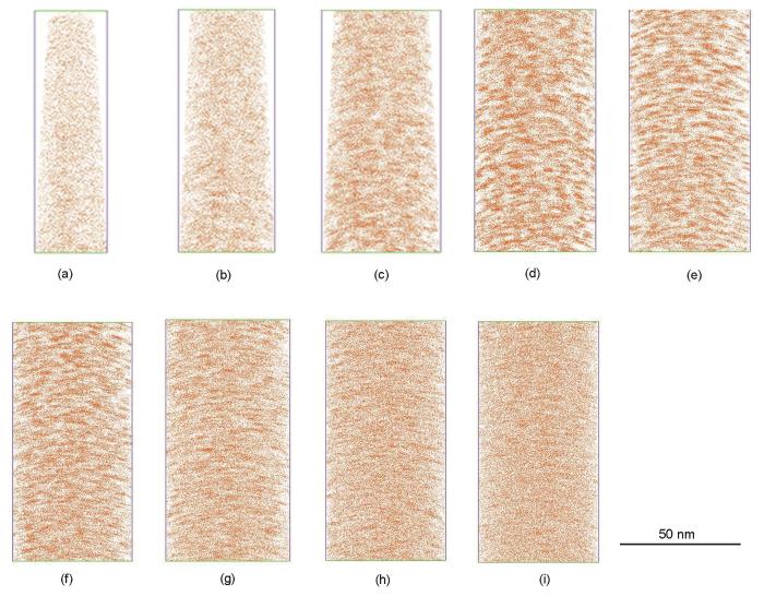
图3
氩离子辐照后Fe-Cu合金距辐照表面不同深度处的Cu原子分布
Fig.3
Cu atom distributions of Ar ions irradiated Fe-Cu alloys as a function of depth
(a) 100-200 nm (b) 200-300 nm (c) 300-400 nm (d) 400-500 nm (e) 500-600 nm
(f) 600-700 nm (g) 700-800 nm (h) 800-900 nm (i) 900-1000 nm
图4为辐照样品中Cu原子的第5近邻分布(nearest neighbor distribution,NND)曲线,代表相邻最近5个Cu原子的间距分布。其中虚线代表Cu原子随机分布于基体时Cu-Cu原子间距理论分布,实线为实际原子间距分布。当样品中溶质原子存在偏聚时,二者会发生偏离[17,18],偏聚区Cu原子间距小,实际分布曲线向左偏移,图中填充区域面积占比反映了Cu原子的偏聚程度。图4a~i中不同深度Cu原子偏聚比例分别为13.8%、24.7%、36.8%、55.5%、55.9%、40.1%、27.7%、16.5%和9.3%,随辐照深度增加,Cu原子偏聚比例先增加后降低,400~600 nm深度处Cu原子偏聚程度较大,这与图3中Cu原子的分布规律一致。
图4

图4
氩离子辐照后Fe-Cu合金距辐照表面不同深度的Cu原子第5近邻分布曲线
Fig.4
5-nearest neighbor distributions of Cu atom of Ar ion irradiated Fe-Cu alloys as a function of depth (Solid line shows distribution of Cu atoms in the reconstruction and dot line shows corresponding distribution for theoretical random distribution of Cu atoms. The area filled with black shows the clustered Cu atoms and corresponding proportion indicates the degree of Cu atoms clustering. D-pair—distance of atom pair)
(a) 100-200 nm (b) 200-300 nm (c) 300-400 nm
(d) 400-500 nm (e) 500-600 nm (f) 600-700 nm
(g) 700-800 nm (h) 800-900 nm (i) 900-1000 nm
进一步利用MSEM算法确定距表面200~300 nm (图3b)、500~600 nm (图3e)和800~900 nm(图3h)深度处的富Cu团簇,选择参数为团簇中原子最大间距Dmax = 0.8 nm,团簇中最小原子数量Nmin = 15,阶数Order = 5[10],并计算3个不同深度区域富Cu团簇的尺寸、数量密度及基体中的Cu含量,结果如表1所示。由表1中数据可看出,随着距表面距离增加,富Cu团簇尺寸和密度均先增加后降低,这与采用NND方法得到的深度方向Cu原子偏聚程度变化规律相同。而辐照样品基体中Cu含量远高于0.05%,与Shu等[10]和Zhu等[9]研究结果不同,表明氩离子辐照抑制了Cu原子的析出。
表1 距表面不同深度处富Cu团簇等效半径、数量密度及基体中的Cu含量
Table 1
| Depth / nm | Rp / nm | Nv / (1024 m-3) | CCu / % |
|---|---|---|---|
| 200-300 | 0.76 | 1.11 | 0.84 |
| 500-600 | 1.07 | 3.48 | 0.52 |
| 800-900 | 0.85 | 1.90 | 1.02 |
随着距表面深度增加至500~600 nm,富Cu团簇尺寸和数量密度均增加,根据SRIM模拟结果,该区域内样品中氩离子浓度比近表面处高,Ar为惰性气体原子,难溶于铁素体基体,会与空位结合形成Ar-V复合团簇或Ar泡(图2)。由于Cu原子与空位也具有较强的结合能力,Ar-V复合团簇迁移过程中会拖拽Cu原子一起扩散,提高了Cu原子的扩散能力,促进富Cu团簇的形成与长大。因此,富Cu团簇的尺寸和数量密度均增加,基体中Cu含量下降。
在氩离子浓度峰值附近(900~1000 nm),损伤剂量迅速降低,点缺陷浓度相应下降,Cu原子扩散能力减弱,团簇尺寸和数量均减小。
3 结论
(1) 1.8 MeV氩离子实际注入深度与模拟深度一致,约为900 nm,辐照层形成大量黑斑缺陷和尺寸为1.3 nm的Ar泡。
(2) 随距表面深度增加,富Cu团簇尺寸和数量密度也先增加后降低,但基体中Cu原子仍保持过饱和状态,Cu原子析出受到抑制。
(3) 近表面处损伤剂量率达到10-4~10-3 dpa/s,高损伤剂量率和大尺寸级联碰撞共同抑制了富Cu团簇的形成;损伤剂量峰附近高浓度Ar+离子形成Ar-V团簇,并在形成Ar泡过程中提高Cu原子扩散能力,促进Cu团簇形成与长大。
参考文献
On the history and status of reactor pressure vessel steel ductile to brittle transition temperature shift prediction models
[J].
Understanding thermally induced embrittlement in low copper RPV steels utilising atom probe tomography
[J].
Motivation for utilizing new high-performance advanced materials in nuclear energy systems
[J].
Opportunities and limitations for ion beams in radiation effects studies: Bridging critical gaps between charged particle and neutron irradiations
[J].
Hardening of reduced activation ferritic/martensitic steels under the irradiation of high-energy heavy-ion
[J].
高能重离子辐照的低活化钢硬化效应
[J].
Evaluation of radiation hardening in ion-irradiated Fe based alloys by nanoindentation
[J].
Evolution of B2 and Laves phases in a ferritic steel under Fe2+ ion irradiation at 475oC
[J].
Structural damage and phase stability of Al0.3CoCrFeNi high entropy alloy under high temperature ion irradiation
[J].
Hardening effects of He irradiation on Fe-Cu alloy
[J].
Precipitation in Fe-Cu and Fe-Cu-Mn model alloys under irradiation: Dose rate effects
[J].
Precipitate evolution in ion-irradiated HCM12A
[J].
On the use of SRIM for computing radiation damage exposure
[J].
Heavy-ion irradiation defect accumulation in ZrN characterized by TEM, GIXRD, nanoindentation, and helium desorption
[J].
Study of irradiation damage in domestically fabricated nuclear grade stainless steel
[J].
国产核用不锈钢辐照损伤研究
[J].
Strategies for fabricating atom probe specimens with a dual beam FIB
[J].
A FIB-based lift-out method for preparing atom probe specimens at site specific locations such as coarse precipitates, grain boundaries, interphase interfaces, denuded zones, heat affected zones, implanted, near surface and subsurface regions, shear bands, etc. has been developed. FIB-based methods for the fabrication of atom probe specimens from thin ribbons, sheet stock, and powders have been developed.
Damage behavior in helium-irradiated reduced-activation martensitic steels at elevated temperatures
[J].
The stability of γ' precipitates in a multi-component FeCoNiCrTi0.2 alloy under elevated-temperature irradiation
[J].
Mining information from atom probe data
[J].
Characterization and modeling of grain boundary chemistry evolution in ferritic steels under irradiation
[R].
The microstructure of “triple-beam” ion irradiated Fe and Fe-Cr alloys
[J].
Flux effects in precipitation under irradiation-simulation of Fe-Cr alloys
[J].
Ballistic effects on the copper precipitation and re-dissolution kinetics in an ion irradiated and thermally annealed Fe-Cu alloy
[J].
The radiation effect of ion species on the microstructure of nanoporous gold
[J].
