


还有很多研究者尝试采用X射线检测金属基复合材料中的缺陷,例如,Yancey和Baaklini[13]研究认为,在金属基复合材料制件的工艺开发过程中,使用电子计算机断层扫描(CT)能识别出增强截面内与纤维填充密度相关的变化,甚至能得到有关纤维间距和分布的信息;Mueller等[14]基于同步辐射X射线,开发了3维X-CT成像和X射线衍射成像相结合的检测技术,可检测出金属基复合材料中纤维/基体的分离缺陷;Hirano等[15]通过基于同步辐射的原位X射线计算机断层摄影术(SR-CT),研究了静态拉伸载荷下SiC纤维增强铝基复合材料的内部损伤扩展过程。本课题组也曾试图用高能加速器X-CT检测直径约600 mm、厚约100 mm的Ti-MMC环,没有得到理想的检测结果。该方法虽然可以对小尺寸内部的纤维断裂进行分析和表征,但是对于尺寸较大的叶环零件的检测却显得无能为力。
由于整体叶环中纤维断丝和断裂是最具危害性的缺陷,本工作针对整体叶环中的深埋型径向微裂纹检测难题,基于超声头波理论[18],提出了一种爬波与水浸聚焦技术相结合的检测方法,并进行了有限元仿真和实验验证研究,以期发展出一种简单快速的整体叶环制造质量检验技术。
1 检测对象与检测方法
1.1 检测对象
图1
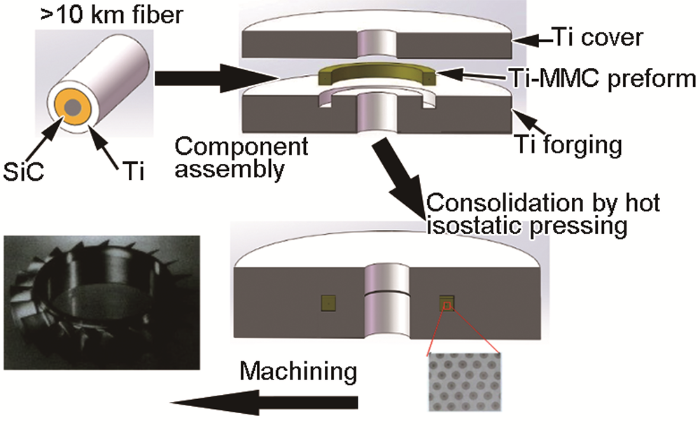
图1
整体叶环制造工艺示意图
Fig.1
The manufacturing process of the integral bladed ring (Ti-MMC—titanium alloy matrix composite)
Color online
在上述制备过程中,如果工艺设计或者控制不当,则可能产生纤维的集中断裂,并可能导致叶环零件的承载能力明显降低[22]。
航空发动机整体叶环坯直径一般为几百毫米,SiC纤维束距叶环坯表面十几到几十毫米不等。如图2将整体叶环坯360°展开,可将被检工件视为多层夹芯结构,断丝是纤维环径向开裂缺陷,因此大多垂直于工件表面。对超声检测而言,断丝缺陷属于垂直于表面的深埋型径向微裂纹,难以检测。
图2
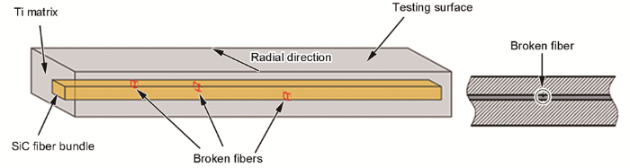
图2
SiC纤维增强钛合金基复合材料(Ti-MMC)整体叶环坯中缺陷形态示意图
Fig.2
Schematics of defect morphology of the integral bladed ring manufactured by SiC fiber-reinforced Ti-MMC
1.2 Heelan头波理论(the theory of head waves)
图3
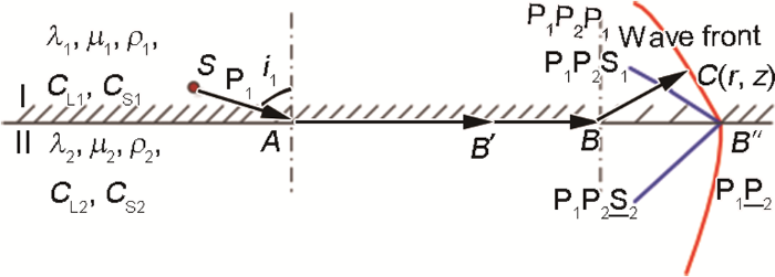
图3
一种特殊纵波P1入射形成的头波系统[23]
Fig.3
A head wave system formed by the incidence of a special longitudinal wave P1 (λ, μ—elastic constants; ρ—density; S—shear wave, P—longitudinal wave; CL—P-wave velocity, CS—shear wave velocity; 1—mediume Ⅰ, 2—mediume Ⅱ; point S—hypocenter; i1—first critical angle; point C(r, z)—arbitrary position on the wavefront in the first medium, r—the horizontal distance from point C to the source; z—vertical distance from point C to the interface)[23]
图3中,P表示纵波,S表示横波,点S表示震源;下角标1表示第一层介质,下角标2表示第二层介质;
从震源S发出的
(1) 随着折射纵波
(2)
(3) 在头波系统的传播过程中,3个头波
(4) 从震源S到第一介质中点C(r, z) (r表示C点到震源的水平距离,z表示C点到界面的垂直距离)的传播路径为:以声速
1.3 检测方案
图4
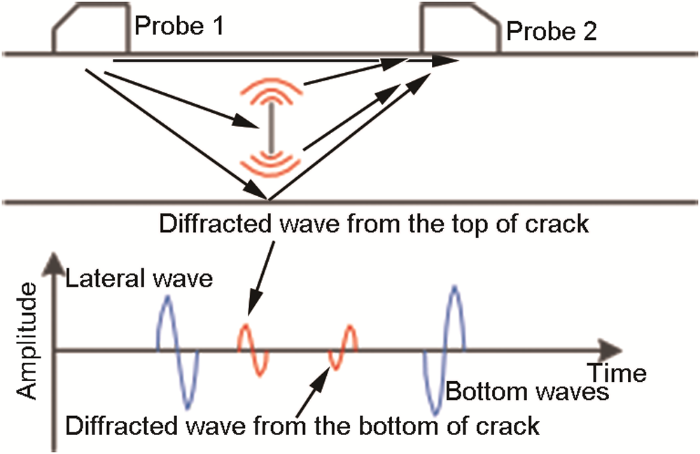
图4
TOFD检测原理示意图
Fig.4
Schematic of time of flight diffraction (TOFD) detection principle
作者课题组曾尝试用TOFD检测整体叶环坯中纤维断丝缺陷,但由于TOFD折射纵波入射到缺陷处的角度不理想,这时的微裂纹衍射信号会太弱,因此无法用TOFD技术进行检测。
本工作根据Heelan头波理论,利用纤维环与钛合金界面这一结构特征所形成的界面爬波沿界面传播的特性,使爬波垂直于微裂纹“撞击”产生衍射波,从而实施检测。
检测实施方案如图5所示。特别设计探头1使之在钛基介质中形成适当角度的折射纵波入射到钛合金-SiC纤维环界面,并在工件内部分层界面上激励出爬波。爬波在传播路径上遇到裂纹时会产生衍射波,以垂直于工件表面的方向向上传播。为了接收这种衍射波,采用垂直于工件表面的水浸聚焦探头以提高检测灵敏度。
图5
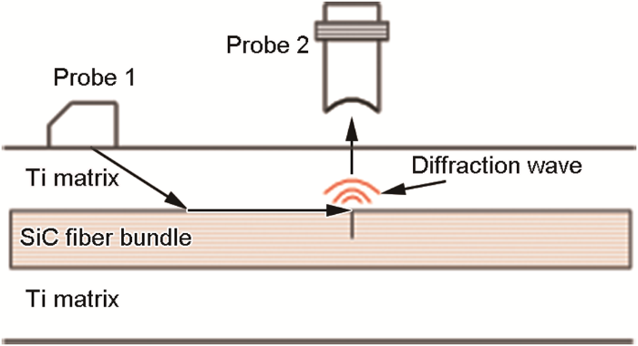
图5
整体叶环坯纤维断丝超声爬波与水浸聚焦组合检测法示意图
Fig.5
The detection method by creeping wave probe and water immersion focusing probe
2 有限元仿真分析
从Heelan头波理论可以看出,在图5所示的多层介质声检测系统中,其超声波型及其传播特性是很复杂的。为了以高灵敏度检测整体叶环坯中的断丝缺陷,需要较好地了解波系统中各种主要波的存在性、传播方向及其幅度分布规律,从而为在探头结构设计时提供参考,以便抑制不利于检测的波形发生。Heelan头波理论主要考虑的小圆柱状声源S,而一般超声检测采用片状的压电晶片,且本工作面对的是多层介质系统,无法直接采用Heelan头波理论进行全面分析,因此,本工作采用有限元法(有限元软件为Comsol Multiphysics)进行仿真分析。
仿真之前,采用多次脉冲回波法,对模拟SiC纤维环的长方条状钛基SiC纤维试样进行了超声测试,测得钛基SiC纤维试样的纤维方向的纵波声速为7969 m/s;另外测得钛合金中超声纵波声速为6100 m/s。仿真时,由于计算资源和能力有限,将仿真模型尺寸按照实际工件进行了缩小,用压电晶片模拟有机玻璃楔块超声探头,以进行原理性分析。
2.1 简单结构头波系统组成仿真与分析
图6

图6
简单结构头波系统组成仿真模型
Fig.6
The simulation model of head wave system in the simple structure
图7
图8
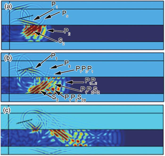
图8
不同时刻(t)的声场分布
Fig.8
The distributions of sound field at different time (t) (Ps—scattered longitudinal wave at the tip of piezoelectric wafer; 1—water medium; 2—Ti alloy medium; P1P2S2d—shear wave derived from the down-interface of Ti alloy board, where d—down)(a) t=1.25 μs (b) t=1.65 μs (c) t=2.75 μs
Color online
从图8a可以看出,超声波入射到钛合金板初期,在水中形成反射纵波P1,在钛合金板中形成折射纵波P2和折射横波S2。P2在水-Ti分界面处几乎与分界面相垂直,而在钛合金板内部向传播反向弯曲。S2波幅度明显高于P2。由于水中不能传播横波,没有横波S1。图中Ps是压电晶片端头的散射纵波,实际探头中,对这种波会处理得较弱。
从图8c可以看出,随着超声波在钛合金板中的继续传播,
从这种简单结构头波有限元模型仿真可以看出,爬波
2.2 整体叶环坯纤维断丝超声检测仿真模型与分析
图9
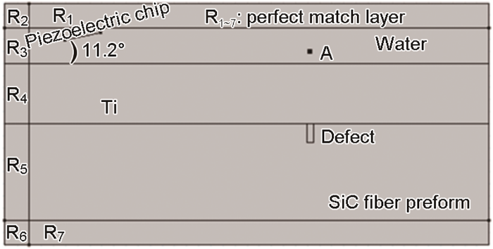
图9
整体叶环坯纤维断丝超声检测仿真模型
Fig.9
The simulation model of the ultrasonic detection for fiber fracture in the integral bladed rings
图10
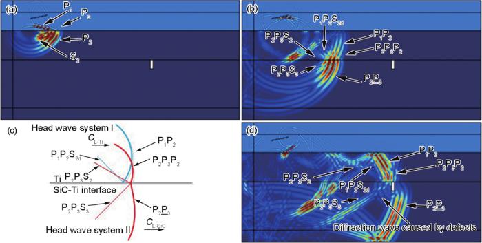
图10
不同时刻的声场分布
Fig.10
The distribution of sound field at different time (CL-Ti—sound velocity of ultrasonic longitudinal waves in titanium alloy; CL-SiC—velocity of ultrasonic longitudinal waves in SiC; 1—water medium; 2—Ti alloy medium; 3—SiC medium)
Color online
(a) t=2.2 μs (b) t=3.45 μs (c) simplified schematic of two head wave systems (d) t=4.9 μs
因此,在Ti-SiC纤维界面,有2个头波系统Ⅰ和Ⅱ分别以CL-Ti和CL-SiC向前传播,由于CL-SiC>CL-Ti,则在相同时间内,头波系统Ⅱ传播距离更远。这2个头波系统Ⅰ和Ⅱ的波型传播可表示为如图10c,图中粗线表示纵波,细线表示横波。
从有限元仿真结果还可以看出,爬波
随着超声波在钛合金板和SiC纤维体中的继续传播,2个头波系统都会在界面不断地发生波型转换并形成一连串“X”形声场。当爬波
当t=6.05 μs时,在缺陷的正上方的水中,可看到缺陷衍射波已进入到水中(图11),可被探头接收到。
图11
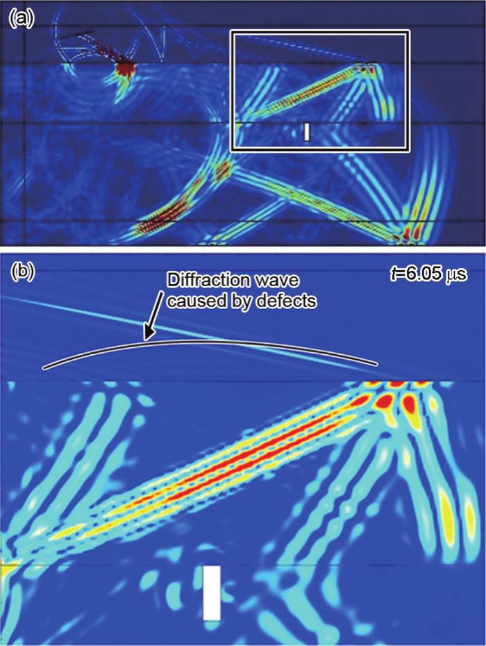
图11
缺陷衍射波进入水中时的声场
Fig.11
The sound fields of the defective diffraction wave incidencing water(a) total sound field(b) partial enlarged sound field
Color online
图12
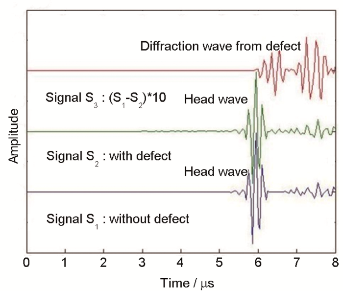
图12
有无缺陷时的信号对比
Fig.12
The comparison of ultrasonic signals with and without defects
2.3 检测影响因素仿真与分析
2.3.1 探头倾角的影响
实际拟采用有机玻璃楔块斜探头在纤维体中激励爬波,经计算,有机玻璃的倾角应为20°。将探头角度分别设为10°、15°、20°及25°,以相同的有限元仿真参数对该复合材料进行有限元仿真,并比较不同探头角度下A点处信号大小,结果如图13所示。结果表明,能激励爬波的探头倾角的合适参数窗口较窄,因此,对探头角度需要严格控制。
图13

图13
探头角度对检测信号幅度的影响
Fig.13
The detection signal amplitude affected by the probe angle
2.3.2 钛合金层厚度的影响
将钛合金层分别设定为5、10、15和20 mm进行有限元仿真,结果如图14所示。可以看出,随着钛合金层厚度的增加,信号幅度按指数衰减。因此,当检测较厚的钛合金层整体叶环时,需要较大的激励功率和较大的接收增益。
图14
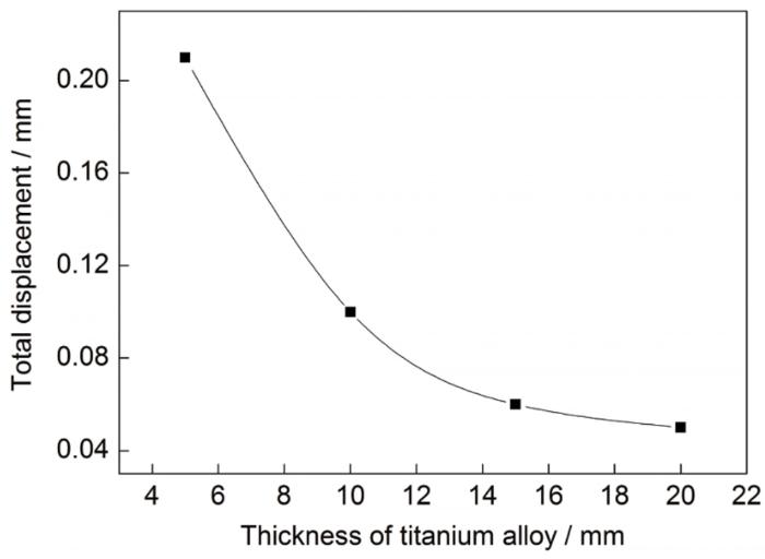
图14
钛合金层厚度对检测信号幅度的影响
Fig.14
The detection signal amplitude affected by the thickness of titanium alloy
3 实验验证及结果分析
上述仿真仅有助于理解纤维断丝爬波检测的主要声学现象,实际检测情况可能更加复杂,因此需要进一步设计制作人工预制缺陷试样,并制作探头组件,开展检测验证实验。
3.1 人工预制缺陷试样设计制作
采用真空热压的方法制备了含人工缺陷的Ti-MMC复合材料板,如图15所示。该复合材料板长152 mm,宽15 mm,厚6 mm,其中纤维芯厚约1 mm。纤维丝分9层,轴线沿板长度方向。在复合材料芯中从一端到另一端引入3处纤维集中断裂,每处贯穿3层纤维丝,分别在1~3层、4~6层和7~9层。
图15
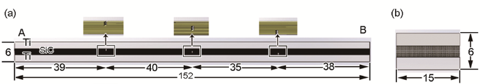
图15
带预制纤维断丝缺陷的Ti-MMC试样
Fig.15
Ti-MMC specimen with the defect of fiber fracture (unit: mm) (a) front view (b) left view
Color online
3.2 探头组件设计制作
根据Snell定律和有限元仿真结果,设计制作了一种特制爬波探头,压电晶片尺寸为10 mm×10 mm,频率为5 MHz;采用20°倾角的有机玻璃楔块固定压电晶片。接收探头为5 MHz水浸聚焦探头,晶片尺寸为直径6 mm,焦距为25 mm。水浸聚焦探头距检测面的距离设计为5 mm。探头组件如图16所示。
图16
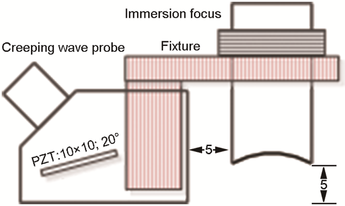
图16
探头组件示意图
Fig.16
The assembled probe (PZT—Pb(ZrTiO3) piezoelectric ceramics; unit: mm)
3.3 人工试样检测结果
利用课题组内自主设计的超声检测系统,采样频率25 MHz,采样深度设为1000个采样点数。将试样A端固定,探头从距离B端20 mm处开始扫查,扫查长度为100 mm,其中每0.02 mm采集一点,对扫查结果进行C扫成像(成像闸门位置:450~550采样点数),如图17所示。
图17
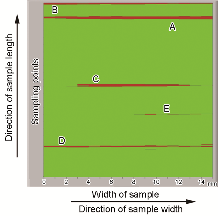
图17
人工试样C扫描检测结果
Fig.17
The C-scan test results of the artificial sample with the broken fiber
Color online
C扫图中A~D点所对应的A扫信号如图18所示。
图18
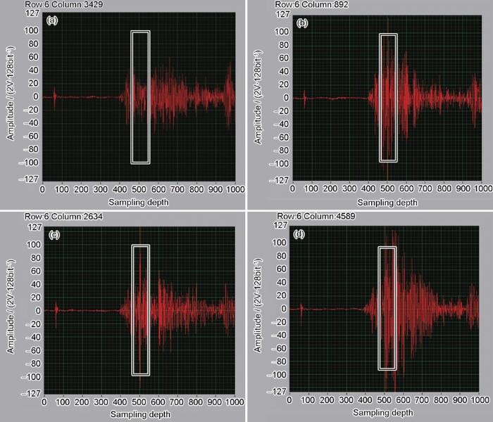
图18
人工试样中典型位置的A扫信号
Fig.18
The A-scan signals of the artificial sample on typical positions corresponding points A~D in Fig.17
Color online
(a) point A without fiber fracture (b) point D with fiber fracture in the lower layer
(c) point C with fiber fracture in the middle layer (d) point B with fiber fracture in the upper layer
从各个A扫信号图中可见,从第400个采样点开始就出现了信号,这是图10d中所标出的P1P2和P2P3P2头波在水中的折射波,在波信号的位置上与仿真分析是相符的,但幅度差别较大,其原因是,聚焦探头并不对准接收这些水中的折射波,而主要是对准接收缺陷的衍射波。因此,该方法能较好地检测出连续SiC纤维增强钛合金基复合材料中的断丝缺陷。
4 结论
(1) 针对整体叶环SiC纤维增强钛合金基复合材料中纤维束断丝缺陷难以检测的问题,基于Heelan头波理论,提出了在纤维层中激励出爬波的检测方法。
(2) 仿真分析表明:在产生爬波的同时会出现复杂的头波现象,其中Ti-水界面的头波以钛合金纵波速度传播,Ti-SiC界面的头波以纤维体纵波速度传播,通过调节入射角,可在SiC纤维体上界面得到较强幅度的纵波“撞击”可能存在的断丝缺陷。然而,与头波在水中的折射波幅度相比,爬波与断丝相互作用产生的衍射波信号仍然较弱。因此采用水浸聚焦探头以最有利于接收缺陷波,可抑制头波折射波对检测的不利影响。
(3) 人工缺陷模拟了三层断丝(自身高度为0.42 mm的断丝裂纹)。对预制SiC纤维断丝缺陷的人工试样的检测实验表明:可有效检测出人工试样中上、中、下层的断丝缺陷。本工作提出的检测方法可以检测航空发动机整体叶环中SiC纤维体中深埋型竖直断丝缺陷。
参考文献
Recent progress in SiC fibre reinforced titanium matrix composites
[J].
SiC纤维增强钛基复合材料研究进展
[J].
Advances in SiC fiber reinforced titanium matrix composites
[J].
α+β) type, metastable β type and near α type, as well intermetallic based γ-TiAl and orthorhombic Ti2AlNb. Along the fiber directions the obtained composites possess exceptional strength and stiffness, creating a large room and great flexibility for the design of higher performance components to be used in both aero engine and aircraft. The composites can be used by itself such as in sheet and bar form, or as a reinforcing module embedded in titanium alloy components, e.g., as a ring at the rim of a compressor disk. In this paper, recent progress in the development and application of SiC fiber reinforced titanium matrix composites was reviewed, emphasizing the work conducted at the Institute of Metal Research, Chinese Academy of Sciences. Five aspects of research were covered, the first is fiber manufacture and batch production, in which the influence of the chemical vapor deposition parameters on the quality of the W-core SiC fiber was discussed, and the relationship between the tungsten-SiC interface reaction and the high temperature stability of the fiber was described. The second part covers the composite interface, in which a detailed discussion was given to both the chemical and physical compatibility, followed by the design of different reaction layers between the SiC fiber and different titanium based matrixs. The mechanical property section presents tensile data of a range of composites developed in the authors' group and compares to literature reports where available, together with a comprehensive discussion of failure due to fatigue and creep. The fourth part deals with nondestructive testing, presenting new results of inspection on real size composite components using a combination of several techniques including X-ray, industrial CT and ultrasonic scanning. The limitations of each method were shown and the technical challenges were identified. The last part describes the development of structural parts and their verification testing. Titanium matrix composite sheets with [0/90] laminate prepared by both the foil-fiber-foil and matrix coated fiber methods were highlighted, followed by a description of the development of full size bladed ring and excess revolution testing. Future directions of research on SiC fiber reinforced titanium matrix composites were also discussed.]]>
连续SiC纤维增强钛基复合材料研究进展
[J].简述了近年来国内外SiC纤维增强钛基复合材料的发展进程和应用进展情况, 从纤维批量化生产、复合材料界面、主要力学性能、无损检测和结构件研制与考核5个方面对该类材料的研究进展进行了回顾. 在纤维批量化生产和复合材料结构件研制方面, 重点介绍了中国科学院金属研究所的研究工作, 并对该类复合材料未来的发展趋势进行了展望.
SiC fibre reinforced titanium matrix composite: Interface evolution and component manufacturing
[J].
SiC纤维增强钛基复合材料界面研究及构件研制
[J].
SiC reinforced titanium corrugated structures for high temperature application
[J].
The advanced design and manufacturing technology of the key component of titanium for aviation engine
[J].
航空发动机用关键钛合金部件先进设计及制造技术
[J].
Development of research on aeroengine bling structure
[J].
航空发动机整体叶环结构的研究进展
[J].
Testing of SiC/titanium composites by fragmentation and push-out tests: Comparison and discussion of test data
[J].
Theoretical analysis of the fiber pullout and pushout tests
[J].
In situ detection of damage in the SiCf/Ti6242 composite during the thermomechanical fatigue test
[J].
SiCf/Ti6242复合材料热机械疲劳损伤原位研究
[J].
Research progress of nondestructive testing for continuous fiber-reinforced metal-matrix composites
[J].
连续纤维增强金属基复合材料无损检测研究进展
[J].
In situ
Comparison of nondestructive microfailure evaluation of fiber-optic bragg grating and acoustic emission piezoelectric sensors using fragmentation test
[J].
Computed tomography evaluation of metal-matrix composites for aeropropulsion engine applications
[J].
Micro crack characterization of metal matrix composite by 3D refraction-computed-tomography
[Z]. https://www.ndt.net/article/wcndt2004/pdf/materials_characterization/262_mueller.pdf
In situ
Investigation of morphology techniques capability for the enhancement of ultrasonic C-scan images of composite patches
[J].
The rapid non-destructive inspection of large composite structures
[J].
The formation mechanism and characteristics of the delayed wave echoes in the slender piece by axial ultrasonic inspection
[J].
细长工件轴向超声检测中迟到波的形成机制及特性
[J].
Materials and design concepts for high performance compressor components
[J].
The interfacial thermal stability and element diffusion mechanism of SiCf/TC17 composite
[J].
SiCf/TC17复合材料界面热稳定性及元素扩散机理
[J].f/TC17复合材料, 并在973, 1023, 1073和1123 K进行长时热暴露实验. 结果表明, 在热压和热暴露过程中, 界面附近的元素扩散形式主要为化学反应和浓度梯度导致的界面互扩散, 以及基体相变扩散. 化学反应扩散是C和Ti扩散的主要动力, 也是反应层形成和长大的原因; 原子浓度梯度使Si, Al, Mo, Cr, Zr和Sn在C层/反应层界面进行下坡扩散, 但扩散程度有限; 基体相变扩散使Al向α相偏聚, Mo和Cr向β相偏聚, Sn向Ti3AlC偏聚, 同时使这些元素的界面互扩散受到抑制. 界面热稳定性研究表明, SiCf/TC17复合材料的反应层长大激活能为138 kJ/mol, 该材料界面在973 K及以下温度是长时稳定的.]]>
Effects of sputtering parameter on the microstructure of Ti-6Al-4V coating on SiC fibre
[J].The effects of sputtering parameters on the microstructure of Ti--6Al--4V coating on SiC(f) prepared by magnetron sputtering were studied. The results show that the deposition rate is related to the working pressure at a given power density. The morphologyof the deposited layer and its binding with the fibre are dependent on temperature. The composition of the coat is close to Ti--6Al--4V, and is uniform throughout the thickness of the coat. The deposited layerconsists of crystallites with nonequilibrium hcp structure with grain size of 20---50 nm. The interface between SiC fibre and Ti--6Al--4V coating was investigated by scanning electron microcopy and energy dispersive X--ray spectroscopy. The examinationreveals no chemical reaction at the fibre--coat interface which is in nature a sharp interface formed by bonding of the two substances.
溅射参量对SiC涂层Ti-6Al-4V显微组织的影响
[J].利用磁控溅射法在SiC纤维上沉积Ti--6Al--4V涂层制备成先驱丝. 在功率密度一定时, 沉积速率和工作气压有关. 环境温度对涂层表面形貌及涂层与纤维结合的影响较大. 涂层成分接近Ti--6Al--4V,沿涂层厚度方向成分分布均匀. 涂层中柱晶晶粒尺寸为20---50 nm, 为α--Ti固溶体.
Room and elevated temperature tensile properties of SiCf/TC17 composite
[A].
An investigation of the relationship between subsurface and head waves by finite element modeling
[J].
Modeling of ray paths of head waves on irregular interfaces in TOFD inspection for NDE
[J].
