


在DMWJ力学性能的表征方面,Ming等[4,5,6,7]通过光学显微镜(OM)、扫描电子显微镜及其能谱仪(SEM/EDS)和电子背散射衍射系统(EBSD)等对三代核电接管安全端DMWJ进行了详细的显微表征。Dong等[8,9]通过慢应变速率拉伸实验,研究了DMWJ的微观结构与晶间应力腐蚀开裂(IGSCC)敏感性的相关性。Wang等[10,11]采用小型平板和三点弯曲试样对DMWJ分别进行了拉伸力学性能实验和不同位置的断裂力学实验,并对不同位置处的断裂模式进行了研究。Blouin等[12]对2种DMWJ进行了低温力学性能表征实验,并测试了不同类型、不同尺寸试样的断裂韧性。Chen等[13,14]通过OM和SEM表征接头微观结构,发现马氏体/焊缝金属边界为熔合边界,而马氏体的形成主要取决于合金元素的分布。Jahanzeb等[15]通过微观观测技术对DMWJ未变形和变形试样的微观结构分别进行了表征,并研究了微观结构对接头硬度不均匀性的影响。
在DMWJ不同位置裂纹的断裂行为方面,各国学者也进行了详细的研究,发现当初始裂纹位于母材或焊缝中心时,裂尖塑性区、损伤区呈对称分布,裂纹基本沿初始裂纹面向前以直线形式扩展,J积分阻力曲线(J-R阻力曲线)较高[16];当初始裂纹位于界面及近界面区时,裂尖塑性区、损伤区呈非对称分布,此时裂纹扩展路径有显著偏离现象,裂纹倾向于向界面两侧屈服应力低的一侧偏转,J-R阻力曲线较低[17,18];当初始裂纹位于熔合线位置时,裂尖两侧形成基本对称的塑性区,随着裂纹的起裂与扩展,塑性区逐渐变得不对称,裂纹扩展路径也随之发生偏转[19,20];当初始裂纹位于热影响区时,裂尖两侧形成非对称的塑性区,局部区域裂纹起裂后,裂纹迅速向焊缝界面偏转,裂纹扩展路径和扩展速率与其微观组织密切相关[19,20,21]。
在几何拘束对DMWJ裂尖力学场与断裂行为的影响方面,Kim等[22]定量表征了面内拘束和面外拘束对裂纹尖端应力三轴度的影响,发现对于高拘束几何试样,试样厚度对裂纹尖端应力三轴度的影响明显,而对于低拘束几何试样,这种影响则不明显。Østby等[23,24]研究了浅裂纹拉伸试样和深裂纹弯曲试样的韧性裂纹扩展行为,发现对于深裂纹弯曲试样,裂纹扩展阻力随着试样宽度的增大而减小,而浅裂纹拉伸试样则相反。本文作者等[25,26,27]曾以核电安全端DMWJ中热影响区裂纹和熔合区裂纹为研究对象,对面内拘束、面外拘束及其交互作用下异种金属焊接接头的断裂机理进行了研究。发现随着面内、面外拘束的增加,DMWJ的断裂机理从延性断裂经由混合断裂转变为脆性断裂,并导致J-R阻力曲线快速降低。
以上研究为构建适用于DMWJ的结构完整性评定方法奠定了基础。然而,针对现役核电站DMWJ中材料拘束的影响,尚缺乏系统性的研究。且此基础上,如何通过对DMWJ的材料拘束进行优化设计以提高其抗断裂能力还需要进一步研究。鉴于此,本工作以核电站DMWJ为研究对象,系统研究了DMWJ中热影响区(HAZ)、熔合区(FZ)和近界面区(NIZ)强度失配引起的材料拘束对DMWJ断裂行为的影响。并在此基础上,对核电站DMWJ各区域的材料拘束进行了优化设计。
1 异种金属焊接接头与试样设计
1.1 异种金属焊接接头
选用新一代核电安全端52M镍基合金DMWJ,其与核电压力容器接管嘴及安全端的连接示意图如图1所示。
图1

图1
异种金属焊接接头与核电压力容器接管嘴及安全端的连接示意图
Fig.1
Connection diagram of the dissimilar metal welded joint (DMWJ) with nozzle and safety end of nuclear pressure vessel
Color online
该DMWJ材料中,接管嘴材料为SA508Gr.3Cl.2低合金钢(简称为A508);安全端过渡短管材料为F316LN奥氏体不锈钢(简称为316L);隔离层和对接焊缝材料均采用52M/ERNiCrFe-7A镍基合金,但焊接工艺不同。制造DMWJ时,先对A508接管嘴进行预热,预热温度为125 ℃,然后通过热丝非熔化极气体保护焊在A508接管嘴上进行多道堆焊,堆焊形成的隔离层宽度约为20 mm,将堆焊形成的隔离层材料记为52Mb。堆焊后,对52Mb隔离层进行焊后热处理。热处理工艺为在610 ℃下退火15 h,之后炉冷到300 ℃。完成热处理后,对52Mb隔离层进行100%涡流无损检测。检测满足质量要求后,进一步进行52Mb隔离层与316L安全端过渡短管之间的对接多道焊。对接多道焊采用多道自动脉冲钨极惰性气体保护焊进行,形成的多道焊缝宽度大约为16 mm,将对接多道焊形成的焊缝材料记为52Mw。焊接完成后,再次对焊缝进行100%涡流无损检测,达到质量要求后,即完成52M镍基合金DMWJ的制作,如图2a所示。A508、316L、52Mb和52Mw 4种材料的化学成分如表1[35]所示。
图2

图2
异种金属焊接接头及A508/52Mb界面附近子区域的细分
Fig.2
The DMWJ (a) and different subareas near the A508/52Mb interface (b) (HAZ—heat affected zone, FZ—fusion zone, NIZ—near interface zone; unit: mm)
表1 异种金属焊接接头4种材料的化学成分[35] (mass fraction / %)
Table 1
| Material | C | S | P | Si | Mn | Ni | Cr | Mo | Cu | Al | Ti | Co | Fe | Nb |
|---|---|---|---|---|---|---|---|---|---|---|---|---|---|---|
| A508 | 0.200 | 0.001 | 0.005 | 0.20 | 1.36 | 0.96 | 0.17 | 0.47 | - | - | - | - | Bal. | - |
| 316L | 0.025 | 0.001 | 0.005 | 0.52 | 1.73 | 11.69 | 17.89 | 2.43 | - | - | - | - | Bal. | - |
| 52Mb | 0.020 | <0.001 | 0.003 | 0.14 | 0.25 | 60.39 | 28.91 | 0.01 | 0.01 | 0.67 | 0.56 | 0.01 | 9.03 | <0.01 |
| 52Mw | 0.025 | 0.001 | 0.004 | 0.18 | 0.24 | 58.00 | 29.18 | 0.01 | 0.02 | 0.75 | 0.53 | 0.02 | 10.23 | <0.01 |
按照力学性能的不同,将该焊接接头A508/52Mb界面附近区域分为HAZ、FZ和NIZ 3区,并按照微观组织和硬度的分布将HAZ进一步细分为A、B、C、D 4个子区域,将NIZ进一步细分为F、G 2个子区域,FZ为单一的E区,如图2b所示。
1.2 材料的力学性能
图3

图3
异种金属焊接接头中所有材料及各子区域的真应力-真应变曲线
Fig.3
The true stress-strain curves of the four materials composed of the DMWJ and different subareas
1.3 试样设计
图4

图4
SENB单边缺口弯曲试样的取样与尺寸示意图
Fig.4
The sampling (a) and geometry (b) of the single edge-notched bend (SENB) specimen (L—distance between the two support points, W—specimen width, B—specimen thickness, F—load)
Color online
分别单独改变HAZ、FZ和NIZ的真应力-真应变曲线以获得不同的材料拘束。在相同真应变下,将变化后材料的真应力与变化前材料的真应力的比值定义为材料拘束失配系数(Ms)。Ms取值为:0.5、0.6、0.7、0.8、0.9、1.0、1.2、1.4、1.6、1.8和2.0。Ms<1时,即在目前DMWJ的基础上降低某一区域的强度;Ms>1时,即在目前DMWJ的基础上增加某一区域的强度;Ms=1时,即为目前DMWJ的实际性能。需要强调的是,在单独改变3个区域中某一区域的真应力-真应变曲线时,该区域内各子区域的真应力-真应变曲线同比例变化,其它2个区域保持不变。
2 有限元数值计算
表2 不同材料的Gurson-Tvergaard-Needleman (GTN)损伤参数[36]
Table 2
| Material | q1 | q2 | q3 | εΝ | SN | fN | f0 | fC | fF |
|---|---|---|---|---|---|---|---|---|---|
| A508 | 1.5 | 1 | 2.25 | 0.3 | 0.1 | 0.002 | 0.00008 | 0.04 | 0.25 |
| 316L | 1.5 | Variable | 2.25 | 0.3 | 0.1 | 0.002 | 0.000001 | 0.04 | 0.25 |
| 52Mb | 1.5 | Variable | 2.25 | 0.3 | 0.1 | 0.002 | 0.000001 | 0.04 | 0.25 |
| 52Mw | 1.5 | 1 | 2.25 | 0.3 | 0.1 | 0.002 | 0.00015 | 0.04 | 0.25 |
| HAZ | 1.5 | 1 | 2.25 | 0.3 | 0.1 | 0.002 | 0.00015 | 0.04 | 0.25 |
| FZ | 1.5 | 1 | 2.25 | 0.3 | 0.1 | 0.008 | 0.00080 | 0.01 | 0.15 |
| NIZ | 1.5 | 1 | 2.25 | 0.3 | 0.1 | 0.002 | 0.00004 | 0.04 | 0.25 |
图5

图5
SENB单边缺口弯曲试样的整体网格与裂尖局部网格
Fig.5
The whole meshes of the SENB specimen (a) and the local meshes at the crack tip (b)
3 核电站DMWJ中材料拘束改变对断裂行为的影响
3.1 HAZ材料拘束改变对断裂行为的影响
单独改变HAZ区域内各子区域真应力-真应变曲线所得到的不同材料拘束下DMWJ的J-R阻力曲线和裂纹扩展路径如图6所示。
图6

图6
HAZ区域材料拘束改变对J-R阻力曲线与裂尖扩展路径的影响
Fig.6
The effects of material constraint changing in HAZ on the J-resistance (J-R) curves (a) and crack growth paths (b) (Δa—crack extension, Ms—ratio of the strength after deformation to the strength before deformation under the same strain)
从图6a中可以看出,在HAZ区域,随着Ms的不断增大即HAZ区域强度的不断增加,J-R阻力曲线不断增高:Ms=0.5时J-R阻力曲线最低,Ms=2.0时J-R阻力曲线最高,且似乎并没有达到极限。由于裂纹位于HAZ区域内,改变HAZ区域的强度将会对DMWJ抗断裂能力有直接的影响,且在现有基础上提高HAZ区域的强度将明显有助于DMWJ抗断裂能力的提升。
从图6b中可以看出,所有的裂纹扩展路径均向左侧偏转,这是因为位于裂纹左侧的B区域的强度低于裂纹右侧C区域强度的缘故。在改变HAZ区域的强度时,4个子区域A、B、C、D的强度同时增加或减小,B区域的强度始终低于C区域,且随着Ms同比例的增加,二者的强度差越来越大,这也是裂纹扩展路径的偏转角度随Ms的增加而逐渐增大的原因。
3.2 FZ材料拘束改变对断裂行为的影响
单独改变FZ区域内各子区域真应力-真应变曲线,得到不同材料拘束下DMWJ的J-R阻力曲线和裂纹扩展路径,如图7所示。
图7
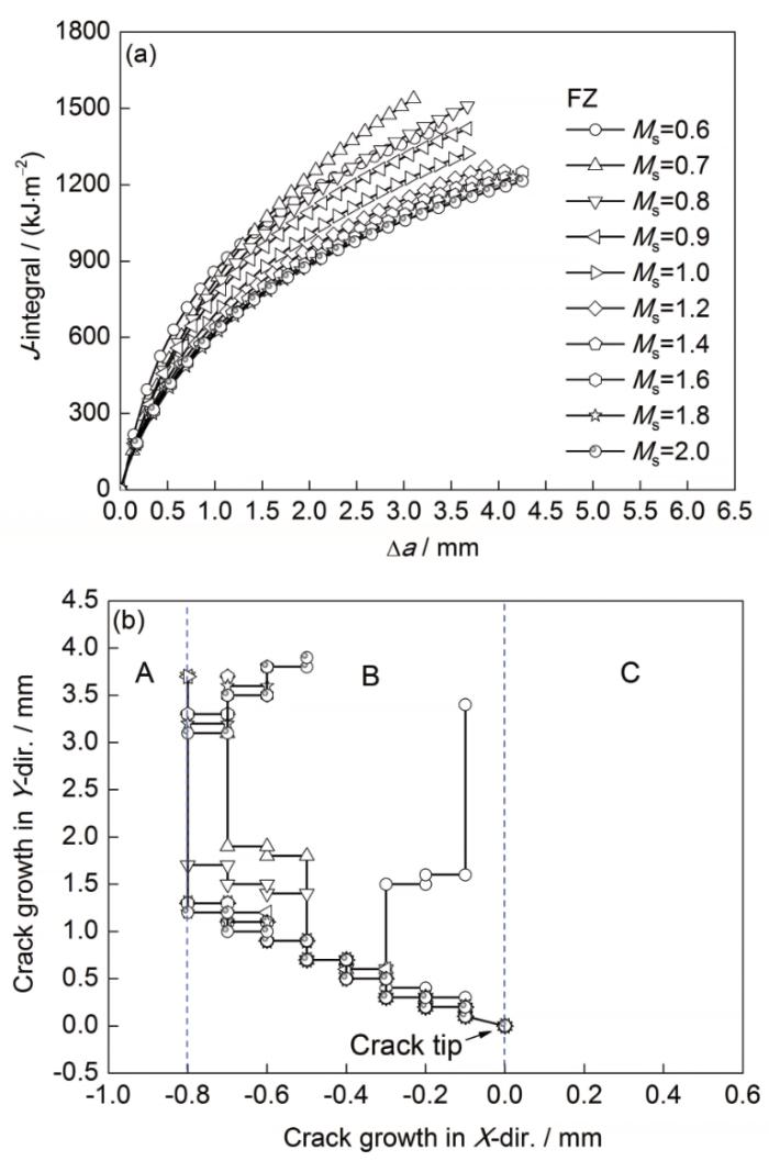
图7
FZ区域材料拘束改变对J-R阻力曲线与裂尖扩展路径的影响
Fig.7
The effects of material constraint changing in FZ on the J-R curves (a) and crack growth paths (b)
从图7a中可以看出,与改变HAZ区域材料拘束不同,随着FZ区域Ms的不断增大即FZ区域强度的不断增加,J-R阻力曲线呈现出先增加后降低最后趋于稳定的变化趋势。在FZ区域,Ms=0.7时J-R阻力曲线最高;当1.6>Ms>0.7时,J-R阻力曲线随着Ms的增大而降低;而Ms≥1.6时J-R阻力曲线趋于稳定,不再随着FZ区域Ms的增大而改变,且此时J-R阻力曲线最低。这说明对于HAZ裂纹而言,在现有基础上适当降低FZ区域的强度反而有助于DMWJ抗断裂能力的提升,而一味提高FZ区域的强度对DMWJ抗断裂能力的提高无益,甚至会起反作用。
从图7b中可以看出,受裂纹两侧材料拘束的影响,所有的裂纹扩展路径依然向左侧偏转,且随着Ms的增加,裂纹右侧的强度逐渐增加,裂纹扩展路径偏转角度也随之增加。当裂纹偏转至A子区域与B子区域界面时,因A子区域的强度高于B子区域,裂纹又向强度较低的右侧偏转。当Ms≥1.6时,裂纹的扩展路径几乎一致。与之明显不同的是,当Ms=0.6时,位于裂纹右侧E子区域的强度明显降低,此时裂纹在局部材料拘束的影响下先向左侧偏转,再转向右侧,最终沿着平行于初始裂纹的方向扩展。
图8
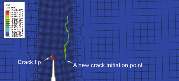
图8
材料拘束失配系数Ms=0.5时的裂纹扩展路径
Fig.8
The crack growth path at Ms=0.5 (VVF—void volume fraction)
Color online
3.3 NIZ材料拘束改变对断裂行为的影响
单独改变NIZ区域内各子区域真应力-真应变曲线所得到的不同材料拘束下DMWJ的J-R阻力曲线和裂纹扩展路径如图9所示。
图9

图9
NIZ区域材料拘束改变对J-R阻力曲线与裂尖扩展路径的影响
Fig.9
The effects of material constraint changing in NIZ on the J-R curves (a) and crack growth paths (b)
从图9a中可以看出,与FZ区域材料拘束改变非常一致,随着NIZ区域Ms的不断增大即NIZ强度的不断增加,J-R阻力曲线呈现出先增加后降低最后趋于稳定的变化趋势。在NIZ区域,Ms=0.6时,J-R阻力曲线最高;1.4>Ms>0.6时,J-R阻力曲线随着材料拘束失配系数的增大而降低;Ms≥1.4时,J-R阻力曲线趋于稳定,不再随着材料拘束失配系数的增大而改变,且此时J-R阻力曲线最低。这同样说明对于该HAZ裂纹而言,在现有基础上适当降低NIZ区域的强度反而有助于DMWJ抗断裂能力的提升,而一味提高NIZ区域的强度同样对DMWJ抗断裂能力的提高无益。
通过对比HAZ、FZ、NIZ区域材料拘束改变所引起的J-R阻力曲线的变化可以看出,当改变裂纹所在区域HAZ区域的强度时,所带来的J-R阻力曲线的改变最为明显,J-R阻力曲线随着该区域材料拘束失配系数的增加而单调增加;当改变裂纹周边区域FZ、NIZ区域的强度时,J-R阻力曲线随着该区域材料拘束失配系数的增加先增加后降低再不变。对本DMWJ而言,适当增加HAZ区域的强度,降低FZ、NIZ区域的强度有助于J-R阻力曲线的提高。
从图9b中可以看出,当Ms=0.5时,裂纹向右侧偏转,这应该是受到右侧NIZ区域强度过低的影响,此时NIZ区域的强度仅为原来的一半,即便裂纹左侧子区域B的强度低于右侧子区域C,裂纹依然向右侧偏转。当Ms=0.6时,右侧NIZ的强度有所提升,此时裂纹在扩展过程中出现了分叉现象,如图10所示。裂纹扩展过程中的分叉现象一般发生在脆性材料中或动载荷加载下的延性材料中,而在准静态加载下的延性材料中较为少见。在脆性材料中或动载荷加载下,这种分叉现象产生的机制与裂纹的扩展速率[37]或裂尖能量释放率[38]有关。本工作中发生的准静态加载下焊接接头中的裂纹分叉现象可能与裂纹左右两侧均存在非常明显的强度失配且左右两侧的强度失配又相对均衡有关。当NIZ区域Ms=0.6时,位于裂纹右侧的F、G子区域的真应力-真应变曲线与位于裂纹左侧的B子区域的真应力-真应变曲线相近,且均弱于中间的C区域,这使得裂纹同时具有向2个方向扩展的动力,从而在裂纹扩展过程中形成了2条裂纹。2条裂纹竞争起裂,最终裂纹主要向左侧扩展,左侧裂纹稍长,右侧裂纹稍短。
图10

图10
Ms=0.6时裂纹的扩展路径
Fig.10
The crack growth path of un-deformed meshes (a) and deformed meshes (b) at Ms=0.6
Color online
这种竞争机制增加了DMWJ的断裂阻力,形成了最高的J-R阻力曲线,如图9a所示。当Ms>0.6后,右侧区域强度增加,裂纹开始向左侧偏转,且随着Ms的增加,裂纹扩展路径偏转角度也随之增加。当Ms≥1.4时,所有裂纹的扩展路径几乎一致。
4 核电站DMWJ中材料拘束的优化设计
由以上结果可以看出,单独变化HAZ、FZ和NIZ区域的材料拘束时,当:
Ms (HAZ):Ms (FZ):Ms (NIZ)=2:1:1;
Ms (HAZ):Ms (FZ):Ms (NIZ)=1:0.7:1;
Ms (HAZ):Ms (FZ):Ms (NIZ)=1:1:0.6
时,分别得到了最高的J-R阻力曲线。
为了寻找DMWJ各区域材料拘束的最佳匹配,在上述结果的基础上,同时改变各区域的材料拘束,进行了如下9组设计:
(1) Ms (HAZ):Ms (FZ):Ms (NIZ)=2:0.7:0.6;
(2) Ms (HAZ):Ms (FZ):Ms (NIZ)=2:0.7:1;
(3) Ms (HAZ):Ms (FZ):Ms (NIZ)=2:1:0.6;
(4) Ms (HAZ):Ms (FZ):Ms (NIZ)=1:0.7:0.6;
(5) Ms (HAZ):Ms (FZ):Ms (NIZ)=1.4:0.7:0.42;
(6) Ms (HAZ):Ms (FZ):Ms (NIZ)=0.84:0.42:0.6;
(7) Ms (HAZ):Ms (FZ):Ms (NIZ)=2:1.4:2;
(8) Ms (HAZ):Ms (FZ):Ms (NIZ)=2:2:1.2;
(9) Ms (HAZ):Ms (FZ):Ms (NIZ)=2:1.4:0.84。
然而,只有第7~9组得到了有效的J-R阻力曲线。将其与单独变化HAZ、FZ和NIZ区域材料拘束时所得的J-R阻力曲线以及实际焊接接头的J-R阻力曲线进行对比,结果如图11所示。
图11

图11
不同材料拘束优化设计所得到的J-R阻力曲线
Fig.11
The J-R curves under different optimized material constraints
从图11可以看出,无论是对各区域材料拘束进行单独优化还是整体优化,材料拘束优化后DMWJ的J-R阻力曲线均明显高于实际DMWJ的J-R阻力曲线,这说明对DMWJ进行优化设计是必要的。
当Ms (HAZ):Ms (FZ):Ms (NIZ)=2:1.4:0.84时所得到的J-R阻力曲线最高,达到了目前焊接接头J-R阻力曲线的几倍之多,此匹配可以作为该DMWJ的最佳匹配。通过对比还可以看出,Ms (HAZ)=2时所得到的J-R阻力曲线均明显高于Ms (HAZ)=1时,这说明对于该DMWJ中的HAZ裂纹,提高裂纹所在区域即HAZ区域的强度,对提高J-R阻力曲线效果最为显著。
最后,必须说明的是,在焊接过程中,仅改变其中一个子区域的性能而保持其它子区域的性能不变很难实现。但本研究结果可为实际焊接接头的优化设计提供一定的方向与参考,为提高DMWJ的可靠性提供一定的借鉴。
5 结论
(1) 对于HAZ裂纹,当单独改变裂纹所在HAZ区域的强度时,J-R阻力曲线随着HAZ区域材料拘束失配系数Ms的增加而单调增加;当单独改变裂纹周边FZ或NIZ区域的强度时,J-R阻力曲线随着FZ或NIZ区域Ms的增加先增加后降低再不变。
(2) 对本DMWJ而言,单独变化HAZ、FZ、NIZ区域的强度时,适当增加HAZ区域的强度、降低FZ与NIZ区域的强度有助于J-R阻力曲线的提高;同时改变HAZ、FZ、NIZ区域的强度时,当Ms (HAZ):Ms (FZ):Ms (NIZ)=2:1.4:0.84时,得到了几倍于目前DMWJ的J-R阻力曲线。材料拘束优化后DMWJ的J-R阻力曲线均明显高于实际DMWJ的J-R阻力曲线,对DMWJ进行优化设计是必要的。
(3) 在裂纹左右两侧均存在非常明显的强度失配且左右两侧的强度失配又相对均衡的影响下,裂纹在扩展过程中将会出现分叉现象。分叉后2条裂纹竞争起裂,这种竞争机制将增加DMWJ的断裂阻力,形成高的J-R阻力曲线。
参考文献
A review of corrosion failure of welded structural metallic materials for light water reactor plant
[J].
核电焊接结构材料腐蚀失效研究现状与进展
[J].
综述了轻水堆 (LWR) 核电站焊接结构材料环境促进开裂 (EAC) 的研究现状,分析了环境、材料、应力等相关影响因素,讨论了几种主要高温高压水EAC机理及考虑EAC效应的设计模型,最后指出了核电焊接结构材料EAC研究面临的问题及进一步的研究方向。
Degradation of a Ni-Cr-Fe alloy in a pressurised-water nuclear power plant
[J].
Fracture assessment for a dissimilar metal weld of low alloy steel and Ni-base alloy
[J].
Microstructure of a domestically fabricated dissimilar metal weld joint (SA508-52M-309L-CF8A) in nuclear power plant
[J].
Microstructure of a safe-end dissimilar metal weld joint (SA508-52-316L) prepared by narrow-gap GTAW
[J].
Microstructure, local mechanical properties and stress corrosion cracking susceptibility of an SA508-52M-316LN safe-end dissimilar metal weld joint by GTAW
[J].
Microstructure and local properties of a domestic safe-end dissimilar metal weld joint by using hot-wire GTAW
[J].3BO3 and 2.3 mg/L Li as LiOH with 2 mg/L dissolved oxygen at 325 ℃. A large amount of type I boundaries and type II boundaries which are susceptible to stress corrosion cracking (SCC) exist in 52Mb near the SA508/52Mb interface and result in the highest SCC susceptibility of this interface. Microstructure transition was found in the SA508 heat affected zone (HAZ). In 316LN HAZ, increasing the distance from the fusion boundary, the number fraction of CSL boundaries increase while the residual strain decreases, resulting in the second-highest SCC susceptibility of 316LN HAZ. In 52M, residual strain distributes randomly but not uniformly, the residual strain is prone to accumulate at the grain boundaries. Dramatic changes of mechanical properties are observed across the joint, especially at the SA508/52M interface. The differences of the local microstructure and chemical composition lead to the differences of the local properties of the weld joint.]]>
国产核电安全端异种金属焊接件的微观结构及局部性能研究
[J].利用OM、SEM、显微硬度仪、微小试样拉伸实验及慢应变速率拉伸实验对国产带热丝隔离层核电安全端焊接件不同部位的微观结构及局部的力学性能和应力腐蚀敏感性进行了研究。发现,在SA508/52Mb界面处的52Mb中具有大量的对应力腐蚀敏感的I型晶界及II型晶界,导致此界面具有最高的应力腐蚀敏感性;SA508热影响区存在明显的组织过渡;316LN热影响区中随着距熔合线距离的增加,重位点阵(CSL)晶界的数量分数逐渐增大,Σ3晶界与理想的Σ3晶界的偏差角减小,残余应变逐渐减小,残余应变的最高值出现在对接焊底焊位置处的316LN热影响区中,导致316LN的热影响区也具有较高的应力腐蚀敏感性。焊接件不同部位的力学性能存在较大的差异。对于硬度分布而言,显微硬度变化最剧烈的位置在SA508/52Mb界面附近,且此界面附近的52Mb具有最高的硬度,此界面附近的SA508脱C区具有最低的硬度。强度的变化趋势与硬度的变化趋势类似。一般强度高的地方断裂应变低。焊接件不同位置的性能差异主要取决于不同部位的微观结构(包含组织、成分等)差异。
Microstructure and intergranular stress corrosion cracking susceptibility of a SA508-52M-316L dissimilar metal weld joint in primary water
[J].
Correlation of microstructure and stress corrosion cracking initiation behaviour of the fusion boundary region in a SA508 Cl. 3-Alloy 52M dissimilar weld joint in primary pressurized water reactor environment
[J].
Local mechanical properties of a dissimilar metal welded joint in nuclear power systems
[J].
Fracture mechanism of a dissimilar metal welded joint in nuclear power plant
[J].
Brittle fracture analysis of dissimilar metal welds
[J].
TEM observation of martensite layer at the weld interface of an A508III to inconel 82 dissimilar metal weld joint
[J].
Microstructural and hardness investigations on a dissimilar metal weld between low alloy steel and Alloy 82 weld metal
[J].
Effect of microstructure on the hardness heterogeneity of dissimilar metal joints between 316L stainless steel and SS400 steel
[J].
An experimental investigation of local fracture resistance and crack growth paths in a dissimilar metal welded joint
[J].
Investigation of failure behavior of ferritic-austenitic type of dissimilar steel welded joints
[J].
Local fracture resistance behavior of interface regions in a dissimilar metal welded joint
[J].
Use of bimetallic welds in nuclear reactors: Associated problems and structural integrity assessment issues
[J].
Characteristics relevant to ductile failure of bimetallic welds and evaluation of transferability of fracture properties
[J].
In-situ SEM study of short fatigue crack propagation behavior in a dissimilar metal welded joint of nuclear power plant
[J].
3-D constraint effects on J testing and crack tip constraint in M(T), SE(B), SE(T) and C(T) specimens: Numerical study
[J].
Numerical simulations of specimen size and mismatch effects in ductile crack growth-Part I: Tearing resistance and crack growth paths
[J].
Numerical simulations of specimen size and mismatch effects in ductile crack growth-Part II: Near-tip stress fields
[J].
An experimental investigation of in-plane constraint effect on local fracture resistance of a dissimilar metal welded joint
[J].
Out-of-plane constraint effect on local fracture resistance of a dissimilar metal welded joint
[J].
Fracture mechanism of cracks in the weakest location of dissimilar metal welded joint under the interaction effect of in-plane and out-of-plane constraints
[J].
Two-parameter characterization of the near-tip stress fields for a bi-material elastic-plastic interface crack
[J].
A constraint based parameter for quantifying the crack tip stress fields in welded joints
[J].
Study on micro region of crack tip of welded joints under different matches of yield stress
[J].
不同屈服强度匹配下焊接接头裂纹尖端微观区域的研究
[J].
Micromechanical assessment of mismatch effects on fracture of high-strength low alloyed steel welded joints
[J].
Unified correlation of in-plane and out-of-plane constraint with fracture resistance of a dissimilar metal welded joint
[J].
Effect range of the material constraint-I. Center crack
[J].
Effect range of the material constraint-II. Interface crack
[J].
Local mechanical properties and Microstructures of Alloy52M dissimilar metal welded joint between A508 ferritic steel and 316L stainless steel
[J].
Micromechanical analysis of in-plane constraint effect on local fracture behavior of cracks in the weakest locations of dissimilar metal welded joint
[J].
Finite elements with embedded branching
[J].AbstractThis paper is concerned with the numerical modeling of crack branching in brittle materials using finite elements with embedded strong discontinuities, that is, discontinuities in the displacement field defining the solution of the underlying boundary-value problem. In particular, new finite elements are developed in this framework accommodating the different branches of the bifurcating discontinuity in the element interior. The key aspect of these developments is the correct representation of the kinematics of these configurations. This is accomplished through the identification of the proper separation modes characterizing these solutions and their incorporation in the discrete strain field of the finite element. The resulting enhanced modes are activated based on a branching criterion depending on the velocity of the crack tip. The performance of the new elements is illustrated with several numerical simulations involving other approaches for the treatment of branching and comparisons with available experimental results.]]>
Strain injection techniques in dynamic fracture modeling
[J].
