


高速工具钢(简称高速钢)是一类特殊的高合金工具钢,具有高硬度、高耐磨性和优良的红硬性等优点,广泛应用于高速切削工具、高载荷模具等。高速钢的微观组织通常由回火马氏体和大量碳化物组成[1,2],碳化物的尺寸、形貌以及分布是决定高速钢综合力学性能的关键[3]。在高速钢发展的早期(传统模铸工艺),研究者便开始通过改善成分、冶炼条件、锻造技术以及热处理工艺制度等方法解决高速钢中粗大共晶碳化物的问题[4~9],但效果甚微。电渣重熔(electroslag remelting,ESR)工艺取代模铸工艺生产高品质高速钢是一个巨大的进步,特别是在改善冶金质量方面效果尤为显著,但其面临的问题仍难以克服:一方面是耗能高、环境污染严重、生产效率低等问题;另一方面,始终无法解决高速钢中碳化物粗化和网状分布等问题[10,11]。粉末冶金(powder metallurgy,PM)工艺是第一个用来提高高速钢凝固过程冷却速率的工业生产技术,可有效解决高速钢制备过程中存在的碳化物粗大和偏析问题,但粉末冶金工艺不仅工序复杂、成本高,且仍存在粉末氧化严重和产品规格受尺寸限制等问题[12,13]。喷射成形(spray forming,SF)是目前高速钢工业化生产的第3种制备技术[14],喷射成形工艺将雾化、沉积过程相结合,具有一步成形的工艺特征,不仅极大地节约了制造工序与生产成本,而且由于兼具半固态和近终形加工技术的特点,还能明显改善工模具钢中碳化物的偏析问题[15~18]。目前,虽然国内喷射成形工艺在高速钢领域的应用已初具规模化,但相关报道和研究成果仍局限于实验室研究阶段[19~21],对工业化生产的喷射成形高速钢组织和性能特征的了解不够深入。
本工作以工业化生产的电渣重熔、喷射成形、粉末冶金M3高速钢为研究对象,首先进行了不同制备工艺M3高速钢的微观组织对比分析,明确喷射成形M3高速钢的组织特征;然后通过力学性能(硬度、抗弯强度、冲击韧性和耐磨性)的对比,分析碳化物尺寸、形貌和分布对力学性能的影响,明确喷射成形M3高速钢的性能优势;最后结合喷射成形M3高速钢中碳化物的形貌和分布特征,研究高速钢在喷射成形过程中的碳化物析出行为。上述研究可为国产喷射成形高速钢的生产提供理论支撑。
1 实验方法
图1
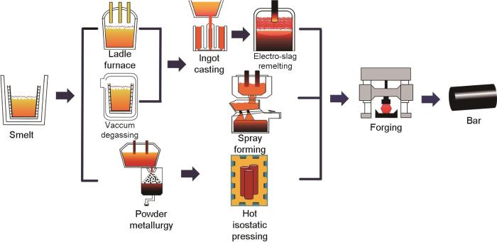
图1
电渣重熔(ESR)、喷射成形(SF)和粉末冶金(PM)工艺流程图
Fig.1
Process flow chart of electro-slag remelting (ESR), spray forming (SF), and powder metallurgy (PM)
表1 不同制备工艺M3高速钢的化学成分 (mass fraction / %)
Table 1
| Steel | C | W | Mo | Cr | V | Fe |
|---|---|---|---|---|---|---|
| SF-M3 | 1.32 | 5.80 | 5.80 | 4.42 | 3.10 | Bal. |
| ESR-M3 | 1.24 | 6.22 | 5.31 | 4.16 | 2.90 | Bal. |
| PM-M3 | 1.32 | 6.00 | 5.60 | 4.02 | 2.97 | Bal. |
利用MEF-4M型光学显微镜(OM)观察退火组织中碳化物的形貌及分布;利用D8 ADVANCE X射线衍射仪(XRD,Co靶,电压35 kV,电流40 mA,扫描角度30°~90°)进行物相分析;利用Quanta 650FEG扫描电镜(SEM)观察钢的退火和淬火组织、断口和磨痕形貌,并使用SEM附带的能谱分析仪(EDS)测定化学成分;利用Image-pro-plus软件结合等效圆面积法统计不同制备工艺样品中的碳化物粒径分布,统计样本为10张SEM照片。考虑到像素等客观因素的影响,仅统计粒径大于0.5 μm的碳化物。
力学性能实验包括:硬度、冲击韧性、抗弯强度和耐磨性。硬度实验热处理工艺为:选取1160、1180、1200和1220 ℃ 4个温度分别进行淬火处理(保温30 min,油冷),之后进行560 ℃的回火处理(保温60 min,空冷),回火次数为3次。冲击韧性、抗弯强度和耐磨性等力学性能实验的热处理工艺为:1180 ℃淬火(保温30 min,油冷) + 560 ℃回火(回火次数为3次,每次保温60 min,其间均以空冷的方式冷却至室温)。利用FR-3E洛氏硬度计测试样品硬度;冲击韧性测试采用尺寸为10 mm × 10 mm × 55 mm的无缺口样品,按照GB/T 229—2007《金属材料 夏比摆锤冲击试验方法》在NI300型冲击试验机上进行;抗弯强度实验采用直径5 mm、长度35 mm的圆棒形非标件在EL0053型疲劳万能试验机上进行三点弯曲测试,变形速率0.02 s-1。“球-板”模式往复对磨摩擦磨损实验在RTEC MFT-5000型摩擦磨损试验机上进行,样品尺寸15 mm × 10 mm × 5 mm,实验参数为:载荷300 N,频率3 Hz,行程3 mm,时间60 min,室温,对磨副为直径9.525 mm的Si3N4陶瓷球。磨损实验完成后,将样品放在无水乙醇中超声清洗,空气吹干。利用UP-2000型白光干涉仪观察磨痕形貌,并测量磨痕深度和磨损体积。
2 实验结果与讨论
2.1 退火组织
图2
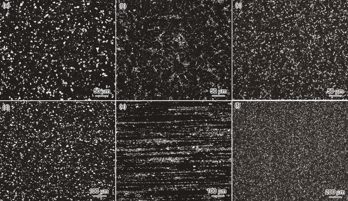
图2
不同制备工艺退火态M3高速钢横截面和纵截面中碳化物形貌及分布的OM像
Fig.2
OM images showing the carbide morphologies and distributions of annealed SF-M3 (a, d), ESR-M3 (b, e), and PM-M3 (c, f) high-speed steels in cross section (a-c) and longitudinal section (d-f)
不同制备工艺M3高速钢的XRD谱如图3a所示。可见,不同制备工艺M3高速钢退火组织中的相组成没有明显差异,均以α-Fe基体、M6C和MC型碳化物为主。不同制备工艺M3高速钢退火组织中碳化物形貌的SEM像如图3b~d所示。与SF-M3 (图3b)和PM-M3 (图3d)高速钢中碳化物呈颗粒状、弥散分布状态不同,ESR-M3 (图3c)高速钢中大尺寸碳化物以复合型片条形貌存在。研究[22,23]表明,这种片条状复合型碳化物是M2C型碳化物的分解产物。M2C型碳化物是常规熔铸工艺凝固过程中析出的主要产物,作为一种亚稳相,通常在后续的退火以及锻轧过程中进一步分解,形成M6C与MC的复合型碳化物。不同制备工艺M3高速钢经1180 ℃淬火后碳化物的粒径分布如图3e所示。可见,PM-M3高速钢中碳化物尺寸基本在2 μm以下;ESR-M3高速钢中碳化物粒径与PM-M3高速钢相当,但存在少量大尺寸碳化物;SF-M3高速钢中碳化物在各粒度区间分布相对均匀,这意味着组织中大尺寸碳化物相对较多。
图3
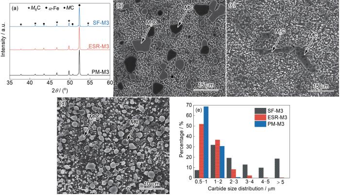
图3
不同制备工艺M3高速钢中碳化物的定性和定量分析
Fig.3
Qualitative and quantitative analyses of carbides in M3 high-speed steel prepared by different processes
(a) XRD spectra (b-d) SEM images of SF-M3 (b), ESR-M3 (c), and PM-M3 (d) high-speed steels (e) carbide particle size distributions of M3 high-speed steels after quenching at 1180 oC
以上实验结果表明,制备工艺对M3高速钢退火组织中的碳化物类型没有影响,但对碳化物的形貌、尺寸与分布的影响较为明显。对于W-Mo系高速钢而言,由于电渣重熔工艺凝固过程中冷却速率相对缓慢,碳化物易在晶界高溶质浓度位置以共晶反应的方式呈网状析出,通过后续锻、轧处理,虽能一定程度上改善网状形貌,但仍有较为严重的碳化物偏聚情况。与此同时,锻造过程中的纵向截面组织中,碳化物将沿加工方向拉长并聚集,演变为带状分布的特征。粉末冶金高速钢精细的微观组织与其工艺密不可分。由于气雾化过程中的冷却速率极高,使基体和第二相的组织明显细化。后续通过热等静压进行粉末的加压烧结,仍然能够保持原始粉末颗粒组织细化的特点,因而退火组织中碳化物尺寸和分布均最为理想。对于喷射成形高速钢,虽与粉末冶金高速钢类似,碳化物具有弥散、颗粒状分布的特征,但粒径明显粗化,这显然与快速凝固抑制组织粗化的行为不相符。
2.2 力学性能
2.2.1 硬度
图4
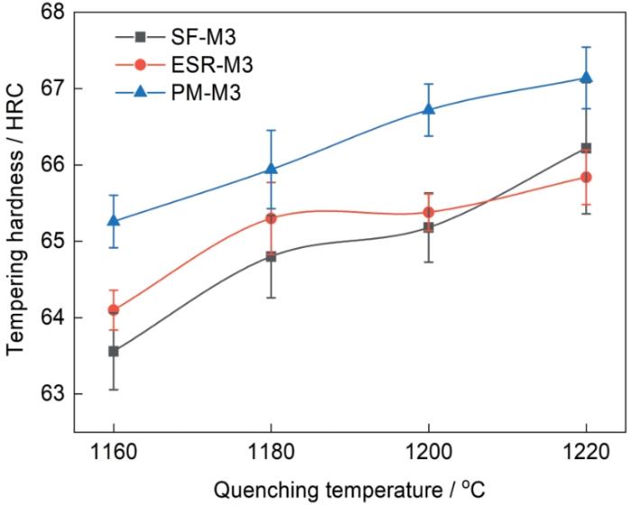
图4
不同制备工艺M3高速钢560 ℃回火后的淬火温度-回火硬度曲线
Fig.4
Quenching temperature-tempering hardness curves of SF-M3, ESR-M3, and PM-M3 high-speed steels tempered at 560 oC
2.2.2 冲击韧性及抗弯强度
不同制备工艺M3高速钢的冲击韧性、抗弯强度和横、纵向力学性能比值如图5所示。可见,PM-M3高速钢具有最优异的综合力学性能;ESR-M3高速钢纵向力学性能相对较好,但较差的横向力学性能,导致其横、纵向力学性能比值最低。SF-M3高速钢的冲击韧性和抗弯强度均较低,但横、纵向的力学性能比值没有明显差异,具有较优的各向同性。
图5
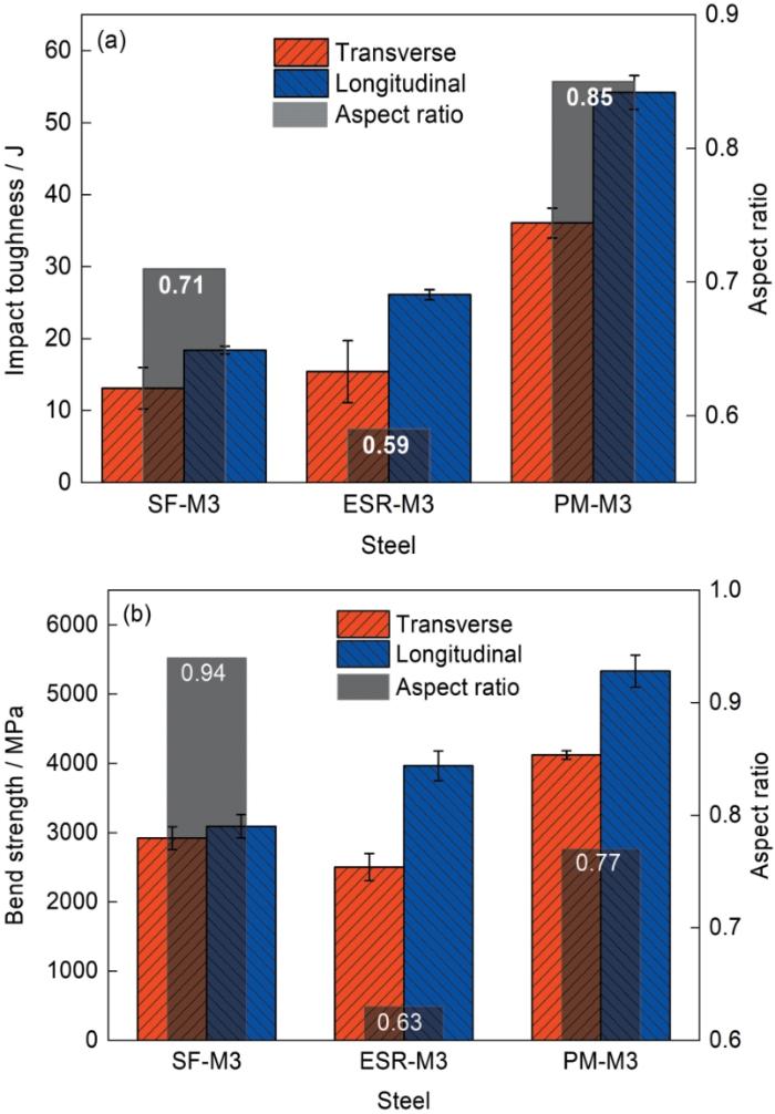
图5
不同制备工艺M3高速钢的力学性能
Fig.5
Mechanical properties of SF-M3, ESR-M3, and PM-M3 high-speed steels
(a) impact toughness
(b) bend strength
图6
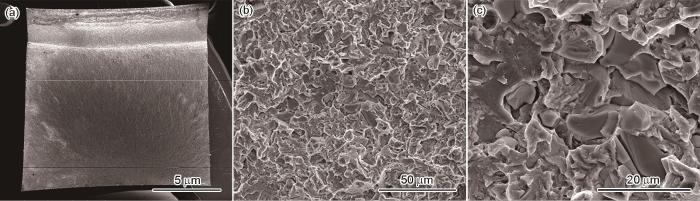
图6
SF-M3高速钢纵向试样冲击断口形貌的SEM像
Fig.6
SEM images of impact fracture in longitudinal SF-M3 high-speed steel specimen
(a) macro fracture morphology
(b) high magnification fracture morphology
(c) secondary fracture of carbides
图7
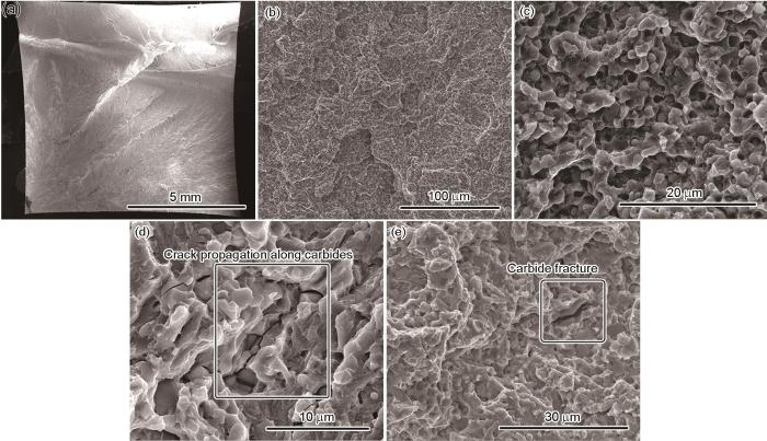
图7
ESR-M3高速钢纵向试样冲击断口形貌的SEM像
Fig.7
SEM images of impact fracture of longitudinal ESR-M3 high-speed steel specimen
(a) macro fracture morphology
(b) micro fracture morphology
(c) characteristics of quasi cleavage fracture morphology
(d) cracks propagate along carbides
(e) large scale carbide fracture
图8
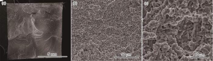
图8
PM-M3高速钢纵向试样冲击断口形貌的SEM像
Fig.8
SEM images of impact fracture of longitudinal PM-M3 high-speed steel specimen
(a) macro fracture morphology
(b) micro fracture morphology
(c) characteristics of quasi cleavage fracture morphology
不同制备工艺M3高速钢的冲击试样受冲击载荷时,试样中产生一定量的应变,基体发生塑性变形,即发生位错的移动和增殖。当位错移动到碳化物颗粒周围时,由于位错塞积作用,将在位错塞积处产生局部应力集中[27],碳化物颗粒断裂所需切应力(τ)可由下式求出:
式中,γ为碳化物解理断裂表面的比表面能;E和ν分别为材料的弹性模量和Poisson比;d为碳化物尺寸。由
ESR-M3高速钢横向试样冲击断口形貌的SEM像及EDS面扫描图如图9所示。与纵向试样断口(图7b)中裂纹扩展呈随机朝向的准解理断裂模式不同,在横向试样冲击断口表面,部分裂纹出现了明显的带状扩展特征,如图9a所示。结合高倍下带状裂纹的观察(图9b)以及相应的EDS面扫描结果(图9c)可以看出,带状裂纹区域内聚集了大量富V、W元素的碳化物,可知带状裂纹的形成与组织中碳化物呈条带分布密切相关。受冲击载荷力时,由于碳化物自身抗断裂强度较低以及与基体的不协调变形,裂纹将优先于碳化物自身断裂处或者碳化物与基体的界面处产生。在带状组织区域内,碳化物聚集程度高,彼此间距近,源于碳化物形成的微裂纹在扩展过程中极易发生交汇、合并等情况,形成宏观裂纹[28,29],加速钢失效行为的发生,导致冲击韧性明显下降。可见,M3高速钢中碳化物的分布状态,对横向力学性能的影响更为明显。
图9
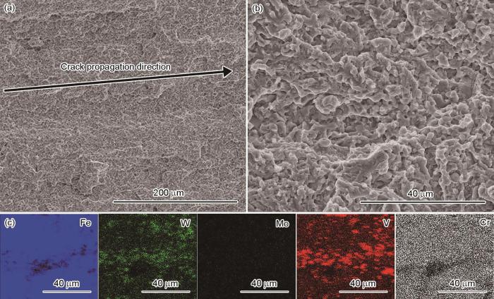
图9
ESR-M3高速钢横向试样冲击断口形貌的SEM像及EDS面扫描图
Fig.9
Low (a) and high (b) magnified SEM images of impact fracture in ESR-M3 high-speed steel specimen for transverse direction, and EDS mapping results (c)
2.2.3 耐磨性能
图10为不同制备工艺M3高速钢磨痕的三维形貌和二维截面深度轮廓图。由图10a、c和e可见,不同制备工艺M3高速钢磨痕区域内均出现大量平行于磨痕方向的犁沟形貌,表现出明显的磨粒磨损特征。测量结果表明,ESR-M3与PM-M3高速钢的磨损体积相近,分别约为0.0295和0.0275 mm3;SF-M3高速钢的磨损体积约为0.0144 mm3,耐磨性能提高了近一倍。为进一步观察磨痕形貌,图10b、d和f给出了不同制备工艺高速钢磨痕在X轴方向的中心位置(1.5 mm)和向左(1.2 mm)、右(1.8 mm)移动0.3 mm位置的磨痕二维截面深度轮廓图。可见,不同制备工艺M3高速钢的磨痕深度存在较大差异,SF-M3高速钢的磨痕深度只有13.5 μm,而ESR-M3和PM-M3高速钢的磨痕深度分别达到了18和19 μm。磨痕深度的增加,意味着ESR-M3和PM-M3高速钢的抗塑性变形能力相对较弱。
图10
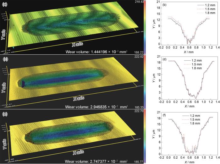
图10
不同制备工艺M3高速钢摩擦磨损样品磨痕三维形貌和二维截面深度轮廓图
Fig.10
White light interference morphologies (a, c, e) and 2D depth contour profiles of cross-section (b, d, f) of wear scar in SF-M3 (a, b), ESR-M3 (c, d), and PM-M3 (e, f) high-speed steels
图11为不同制备工艺高速钢摩擦系数(COF)随滑动时间变化曲线。可见,不同制备工艺高速钢的COF随时间变化趋势可大致分为先上升,后下降,再上升至平稳4个阶段。可见,ESR-M3和PM-M3高速钢COF变化的时间节点较为相近,30 s达到COF峰值(阶段Ⅰ);30~170 s时COF曲线整体呈下降趋势(阶段Ⅱ);70~400 s时COF曲线整体呈上升状态(阶段Ⅲ);500~3600 s时COF曲线整体呈稳定状态(阶段Ⅳ),稳态下ESR-M3和PM-M3高速钢的COF分别约为0.54和0.52。SF-M3高速钢COF曲线呈下降趋势的持续时间相对较长(阶段Ⅱ),约30~500 s,且在此时间段内,COF曲线起伏变化较为明显;500~850 s时COF曲线整体呈上升状态(阶段Ⅲ);850~3600 s时COF曲线整体呈稳定状态(阶段Ⅳ),稳态下SF-M3高速钢的COF约为0.46。
图11
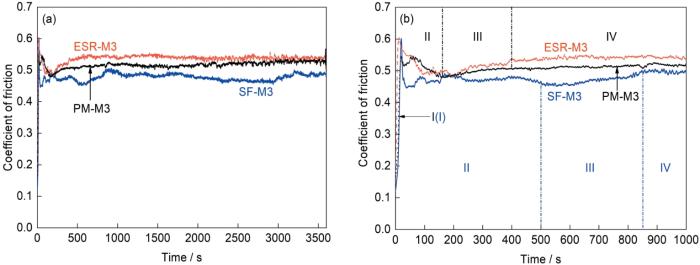
图11
不同制备工艺M3高速钢摩擦系数随滑动时间的变化
Fig.11
Changes of friction coefficient with sliding time for SF-M3, ESR-M3, and PM-M3 high-speed steels (I—break-in stage; II—formation stage of oxidation layer; III—failure stage of oxidation layer; IV—failure-formation dynamic equilibrium stage of oxidation layer)
(a) 3600 s (b)1000 s
图12
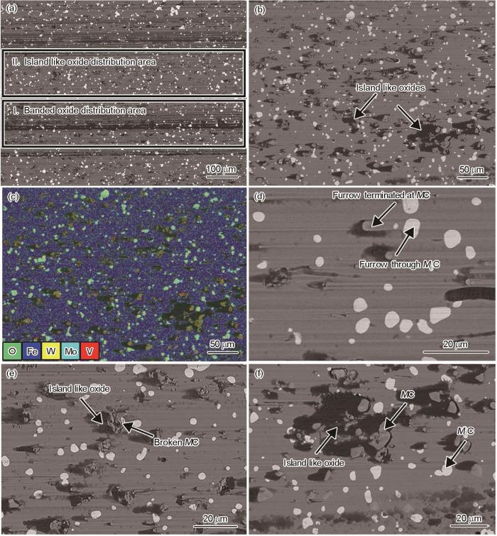
图12
SF-M3高速钢表面磨痕的SEM分析
Fig.12
SEM analyses of wear scar in SF-M3 high-speed steel
(a) SEM image of wear scar morphology
(b) high magnification SEM image of region II in Fig.12a
(c) EDS mapping
(d) crushed MC type carbides
(e) complete MC type carbides
(f) plow morphology
从图12d~f可见,SF-M3高速钢中不同类型碳化物在磨损过程中的表现存在明显差异。对于MC型碳化物,一方面是犁沟形貌的终止点(图12d)表明对磨球的切削以及磨粒的刮擦具有明显的阻碍作用,虽然在磨痕区域内观察到部分MC型碳化物出现破碎的情况(图12e),但源于MC碳化物的裂纹并没有向基体组织中发生扩展,说明在磨损过程中,SF-M3高速钢基体组织仍能起到良好的增韧效果,与碳化物保持较高的结合强度[30,31];另一方面,氧化产物更倾向于在MC型碳化物周围聚集(图12f)。而对于M6C型碳化物,一方面在M6C型碳化物表面能够清楚地观察到犁沟划过的痕迹(图12d),说明M6C型碳化物对抵抗磨削的作用相对较弱;另一方面,也没有起到类似于MC型碳化物聚集氧化物的效果。
图13
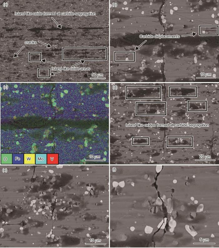
图13
ESR-M3高速钢表面磨痕的SEM分析
Fig.13
SEM analyses of wear scar in ESR-M3 high-speed steel
(a) SEM image of wear scar morphology
(b) morphology of banded oxide and displacement phenomenon of carbides
(c) EDS mapping
(d) oxide layer distributed at the location of carbide segregation
(e) cracks originating from the carbide/matrix interface
(f) cracks through carbides
图14为PM-M3高速钢表面磨痕的SEM分析。从图14a~c可见,PM-M3高速钢的磨痕区域同样存在大量氧化物,但氧化产物具有相对均匀的分布特征,这可能与PM-M3高速钢中碳化物的均匀分布有关。结合PM-M3高速钢磨痕表面出现大量与滑动方向平行犁沟特征观察结果(图10e),基本可以判断PM-M3高速钢的磨损机制也以磨粒磨损和氧化磨损为主。PM-M3高速钢磨损表面同样存在大量垂直于滑动方向的裂纹,但裂纹尺寸较ESR-M3高速钢小,如图14a所示。从图14d可见,源于碳化物断裂或碳化物与基体界面处形成的裂纹,有逐渐向基体中发生扩展的趋势。除上述特征外,在ESR-M3和PM-M3高速钢中,均能够观察到小尺寸碳化物发生位移的情况(图13b和14b)。
图14

图14
PM-M3高速钢表面磨痕的SEM分析
Fig.14
SEM analyses of wear scar in PM-M3 high-speed steel
(a) SEM image of wear scar morphology
(b) uniformly distributed oxides and displacement phenomenon of carbides
(c) EDS mapping
(d) crack initiation and propagation
图15为不同制备工艺M3高速钢磨损过程中的磨痕表面组织演变示意图。在金属摩擦副干滑动磨损的初始阶段,首先直接接触的是磨损表面的微凸体,当剪切应力超过材料的屈服极限时,微凸体将发生断裂,产生大量摩擦颗粒。部分硬质相颗粒(氧化磨屑、Si3N4)或Si3N4球的微凸体将作用于摩擦样品表面,发生强烈的犁削作用,形成大量的犁沟,并随着磨损过程的进行持续发生。大量高硬度的碳化物在基体被磨削后逐渐露出表面。这些露出表面的碳化物将作为主要的承载物承受法向载荷及摩擦,从而有效保护基体不被快速磨损[35] (图15a~c中的阶段I)。从本工作SEM观察结果来看,相比于M6C型碳化物,硬度更高的MC型碳化物对阻碍磨屑犁削的作用更为显著。但需要注意的是,相比于大尺寸碳化物,ESR-M3和PM-M3高速钢中尺寸相对较小的碳化物在硬质相不断切削基体的过程中暴露出基体表面时,在循环往复的载荷下更容易脱离基体,发生滚动、拖尾等行为(图13b和14b),这将加剧磨粒磨损的作用[36],使得磨损体积进一步上升。
图15
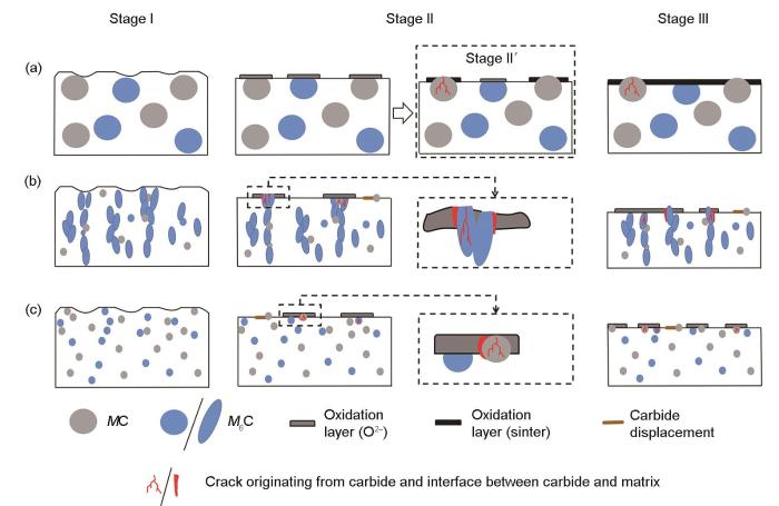
图15
不同制备工艺M3高速钢磨损机制示意图
Fig.15
Schematics of wear mechanisms of SF-M3 (a), ESR-M3 (b), and PM-M3 (c) high-speed steels
随着磨损过程的进行,摩擦所产生的热量逐渐增多,磨面整体和接触点的温度将不断升高[37],极易与大气环境接触发生氧化反应,形成氧化层。氧化物高硬度的特征使其能在摩擦副间起到固体润滑剂的作用,有利于摩擦系数的降低以及磨损体积的减少[38]。磨损过程中氧化层的形成方式主要为以下2种:(1) 原位反应形成机制[39],氧化膜通过O2-的空位扩散机制成形,随着O2-的扩散,氧化过程由氧化物-金属界面向金属基体推进,最终形成具有一定厚度的氧化层,为材料的磨损提供保护;(2) 磨屑聚集烧结形成机制[40],磨损过程中形成的氧化层容易剥落,成为磨屑颗粒,如果磨屑能够堆积在一起,且在摩擦力和压应力的作用下被进一步压实、烧结,形成致密的氧化釉质层,则具有较强的承载能力,能够对基体起到较好的保护作用。
在ESR-M3和PM-M3高速钢磨损过程中,氧化层的形成更倾向于原位扩散机制。在磨损过程中,碳化物硬度远高于基体,起主要抗磨作用。瞬时的摩擦热将会集中于碳化物位置处,首先发生氧化反应,形成氧化层。研究[41]表明,在10~100 N载荷力、滑移速率2~5 m/s的无润滑条件下,低合金钢形成的氧化层厚度通常为1~5 μm。ESR-M3和PM-M3高速钢组织中的碳化物较小且尺寸小于形成的氧化层厚度,这意味着当氧化层生长至一定厚度后发生断裂时,碳化物将随着氧化层的失效与氧化层一起脱落。可见,小尺寸碳化物只能为氧化层的形成提供条件,但不能对氧化层起到良好的相互支撑、保护作用。除此之外,在往复摩擦过程中循环载荷导致的热软化作用以及O2-不断扩散进入组织中附带的高晶格应变的条件下,不仅基体和碳化物自身强度会不断降低,2者间的结合力也进一步下降[41]。这便导致了在碳化物/基体界面处或碳化物自身发生破碎的情况下裂纹的形成,并在循环的载荷作用下,进一步加剧了裂纹在基体组织中的扩展(图15b和c中的阶段Ⅱ)。由此可以判断,磨痕区域内大量裂纹的存在是载荷的反复作用以及氧化加剧内应变的综合结果。对于ESR-M3高速钢,组织中碳化物聚集程度较高,源于碳化物形成的裂纹在扩展过程中更易交互、合并成宏观尺度的裂纹[42]。裂纹在基体组织中的萌生与扩展进一步加剧了磨损失效,磨损体积上升。
对于SF-M3高速钢,磨损过程中氧化膜更倾向于由磨屑堆积、烧结而成(图15a中的阶段Ⅱ)。磨损过程中由于基体不断被磨削,以及依靠原位反应形成的氧化层不断地生成、破碎,使得MC型碳化物逐渐突出于基体表面。由于SF-M3高速钢中MC型碳化物尺寸较大,因而随着摩擦磨损过程的进行,MC型碳化物将突出基体表面并在高度方向上与基体组织存在高度差。正是由于这种高度差的存在,使MC型碳化物逐渐成为磨屑颗粒聚集的位置[43],并且在摩擦力和压应力的作用下,堆积在MC型碳化物周围的磨屑颗粒将被压实、烧结形成氧化釉质层,与MC型碳化物共同抵抗磨损(图15a中的阶段Ⅱ')。随着磨损过程的进行,这种釉质层将沿滑动方向堆积生长,如图12a中区域Ⅰ与区域Ⅱ所示,推测这是不同阶段氧化釉质层的动态形成过程。在氧化釉质层以及MC型碳化物的共同保护下,氧化层以下的基体组织仍能保持相对较高的强度和稳定性,在为MC型碳化物提供支撑的同时,阻止了源于MC型碳化物的裂纹进一步向基体中扩展,因而硬度较低的SF-M3高速钢却具有更优的耐磨性能。
当M3高速钢磨痕区域形成一定量的氧化层后,随着磨损过程进行,氧化层的形成将处于失效-形成的平衡动态过程(图15a~c中的阶段Ⅲ)。
2.3 SF-M3高速钢凝固过程中碳化物析出行为
早期对喷射成形工艺的了解大多基于实验室阶段的研究成果,由于样品规格小、重量低(通常在20 kg范围内),雾化液滴通过与雾化气和沉积基板交换热量的方式将具有极高的冷却速率,因而样品表现出明显的快速凝固组织特征,晶粒和碳化物尺寸均能够得到明显细化。但当喷射成形工艺应用于工业生产时,随着产品规格和重量不断增大,喷射成形沉积阶段的凝固冷却速率亦将发生截然不同的变化。Zepon等[45]利用热电偶测试了喷射成形D2冷作模具钢(重量100 kg)的糊状区随沉积过程进行的温度场变化情况,发现在沉积、凝固过程中,表面糊状区温度的变化可大致分为4个阶段:(Ⅰ) 沉积、凝固初期阶段,当雾化液滴沉积于基板时,可通过与基板的热量交换实现快速散热,沉积表面糊状区温度通常低于200 ℃;(Ⅱ) 沉积稳态阶段,随着喷射、沉积时间的推移,沉积坯高度不断增加,逐渐失去与基板的传热效应,沉积坯表面糊状区温度快速上升,并维持在近似恒定的某一固/液两相区温度(糊状区温度约1335 ℃);(Ⅲ) 沉积结束阶段,此时不再有熔融金属液滴作用于沉积坯表面,但雾化气仍未停止,糊状区通过与雾化气接触的方式散热,糊状区表面温度快速下降(糊状区表面温度从1335 ℃快速降低至1025 ℃);(Ⅳ) 缓慢冷却、凝固阶段,当雾化气体中断后,沉积表面约以20 ℃/min的速率自然冷却。通过结合沉积过程中的Ⅱ和Ⅳ阶段温度场变化情况的分析不难推断,在沉积的稳态阶段,当雾化液滴不断作用于糊状区表面时,不仅提供了源源不断的热量输入,使糊状区的冷却速率较20 ℃/min的自然冷却速率更低,而且持续冲击作用引起的液相流动也将使糊状区的化学成分和温度进一步均匀化。因而可近似认为,喷射成形稳态阶段的凝固行为,更倾向于以一种近平衡固态凝固的方式进行。
基于上述观点,通过Thermal-Calc软件中的Equilibrium模型,计算得到的喷射成形M3高速钢沉积过程中碳化物析出行为,如图16所示。可以看出,平衡凝固过程后期,M3高速钢组织中的M6C和MC型碳化物可直接由沉积坯糊状区液相直接析出。形核后的碳化物,一方面其长大过程受合金元素扩散的影响,在沉积、凝固阶段的缓慢冷却条件下,碳化物拥有足够长的生长时间,以满足其生长所需合金原子远程扩散的成分需求,导致碳化物在糊状区发生长大、粗化;另一方面,碳化物的生长与局部奥氏体的生长快慢也有很大的关系,2者生长速率的匹配关系将影响碳化物以块状孤立或者片层共晶形貌析出。当碳化物的生长快于邻近奥氏体生长时,主要形成块状孤立碳化物,而当2者的生长速率相近时,或者液析碳化物生长速率慢于奥氏体时,将倾向于形成片层共晶碳化物。在喷射成形沉积阶段的缓慢冷却条件下,奥氏体生长较碳化物更为缓慢,使得喷射成形M3高速钢中碳化物更容易形以块状、孤立状的方式出现[46,47]。由此,便解释了喷射成形M3高速钢退火组织中液析碳化物尺寸大,弥散、独立分布的特征。
图16
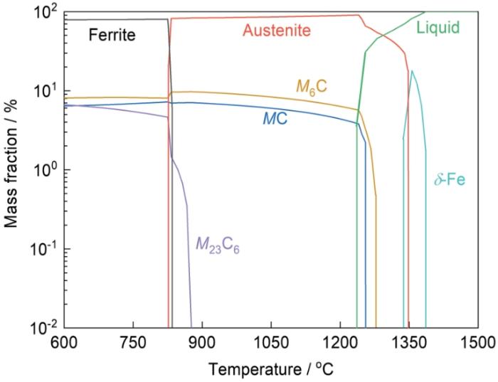
图16
Thermol-Calc软件中Equilibrium模型的碳化物析出计算结果
Fig.16
Calculation results of carbide precipitation obtained by Equilibrium model in Thermol-Calc software
3 结论
(1) 不同制备工艺M3高速钢中碳化物的类型相同,但形貌、尺寸以及分布存在较为明显的差异。粉末冶金高速钢横、纵截面组织中碳化物均表现出最精细的微观结构和最均匀的分布状态;电渣重熔高速钢横截面组织中碳化物呈断网状分布,纵截面组织中碳化物呈条带状分布;喷射成形高速钢横、纵截面组织中碳化物呈弥散的颗粒状分布,但碳化物尺寸较为粗大。
(2) 钢中碳化物尺寸是决定M3高速钢硬度、冲击韧性和抗弯强度的主要因素,碳化物分布均匀性决定M3高速钢的横、纵向力学性能比值。高速钢中碳化物颗粒尺寸越小,分布越均匀,钢的综合力学性能越高。
(3) 喷射成形高速钢具有最优的耐磨性能,粉末冶金高速钢和电渣重熔高速钢耐磨性能相近。喷射成形高速钢中大尺寸的MC型碳化物是影响耐磨性能的关键,一方面在磨损过程中起到优异的抗磨效果;另一方面可以改变氧化层的形成方式,以减少裂纹在基体组织中的形成与扩展。
(4) 喷射成形M3高速钢中碳化物尺寸较大与喷射成形沉积阶段的近平衡凝固特征密切相关。M3高速钢中M6C和MC型碳化物可由沉积坯糊状区液相直接析出,在沉积、凝固阶段的缓慢冷却条件下,导致碳化物粗化行为发生。
参考文献
Solidification of M2 high speed steel
[J].
Solidification of high-speed tool steels
[J].
Different carbide types and their effect on bend properties of a spray-formed high speed steel
[J].
Recent innovations in electroslag remelting
[J].
Electroslag remelting of high technological steels
[J].
On the increase of intrinsic workability and hot working temperature range of M42 ledeburitic super high steel in as-cast and wrought states
[J].
Effects of alloying elements on microstructure and fracture properties of cast high speed steel rolls: Part II. Fracture behavior
[J].
Refining carbide size distributions in M1 high speed steel by processing and alloying
[J].
Influence of heat treatment on the microstructural evolution and mechanical properties of W6Mo5Cr4V2Co5Nb (825 K) high speed steel
[J].
Control of carbide precipitation during electroslag remelting-continuous rapid solidification of GCr15 steel
[J].
Carbide segregation control in electro-slag remelting withdrawal process of large cross-section high-speed steels
[J].
抽锭电渣重熔大截面高速钢过程的碳化物偏析控制
[J].
Problems in high-speed steel manufacture and use: A challenge for economic powder metallurgy processing
[J].
Development of robust processing routes for powder metallurgy high speed steels
[J].
Why is spray forming a rapid solidification process?
[J].
High-speed steels produced by conventional casting, spray forming and powder metallurgy
[J].
Analysis of spray formed tool steels
[J].
Advanced tool steels produced via spray forming
[A].
Research of microstructure and properities of spray formed high alloyed high speed steel
[D].
喷射成形高合金高速钢的组织与性能研究
[D].
Microstructures and properties of spray formed Nb-containing M3 high speed steel
[J].
The billets of M3 high speed steel (HSS) with or without niobium addition were prepared via spray forming and compared with traditional cast steels with same composition, followed by hot forged and heat treated. The corresponding microstructure evolutions of steels induced by niobium have been investigated using SEM with EDS, XRD, OM, TEM and HRTEM. The results show that finer and uniformly-distributed grains without macrosegregation appear in the as-deposited HSS that are different to the as-cast HSS, 1% (mass fraction) niobium addition can promote the formation of primary MC-type carbides before onset of eutectic reaction, which can make the MC particles refined and evenly distributed. Niobium mainly contribute to the primary MC-type carbides by consuming carbon, the eutectic reaction is suppressed and the quantity of M2C eutectic carbides decrease, leading to more W and Mo atoms dissolve into matrix. Compared to spray formed M3 HSS, the niobium alloying M3 HSS possesses higher stability during austenitization, induced by the high stabilization of Nb-containing MC carbides, which can pin the grain boundaries and keep the grain size of primary austenite below that of spray formed M3 HSS. The quenched hardness of niobium-containing steel is remarkably higher, while the over tempering hardness of it is a little below than that of M3 HSS, it is related to the difference of dissolution rate of carbides during austenitization and the precipitation behavior of the secondary carbides after tempering. The amount of Nb-containing MC carbides are hard to dissolve into matrix, additionally, lower content of M2C carbides are in the as-deposited steel, leading to the larger numbers of nano-scaled M2C secondary carbides precipitate after tempering. Spray formed niobium-containing steel has a more advanced hardness and bending strength compared with ASP23, but possesses a lower impact toughness due to that the stress concentration can easily caused by mass of harder MC carbides distributed in matrix.
喷射成形含铌M3型高速钢组织与性能研究
[J].采用喷射成形快速凝固技术制备了M3型高速钢和以Nb代V的M3型高速钢. 利用SEM(EDS), XRD, OM, TEM, HRTEM研究了Nb对M3型高速钢组织的影响和其组织演变. 结果表明, 喷射成形消除了宏观偏析, 细化了组织, 以Nb代V, 可在共晶反应前析出MC型碳化物, 使其球形化、均匀分布, 由于消耗大量C, 共晶M<sub>2</sub>C碳化物数量减少, 促使更多W和Mo固溶进基体. 均匀分布的高热稳定性含Nb-MC型碳化物能阻碍奥氏体化过程中晶粒长大, 但难以固溶, 使得回火过程中主要析出与基体共格的M<sub>2</sub>C型碳化物. 喷射成形含Nb钢硬度和弯曲强度高于ASP23钢, 大量硬质MC碳化物易于产生应力集中, 使其韧性稍低于ASP23.
Microstructure and properties of high vanadium steel with 9% vanadium fabricated by spray forming- hot isostatic pressing
[J].
喷射成形—热等静压9V高钒钢的组织与性能研究
[J].
Research on preparation technology of high-vanadium HSS by spray forming
[J].
喷射成形高钒高速钢环坯制备技术研究
[J].
Microstructural changes in as-cast M2 grade high speed steel during hot forging
[J].
Solidification microstructure and M2C carbide decomposition in a spray-formed high-speed steel
[J].
Tempering characteristics of conventional high-speed steel EM42 and powder metallurgical high-speed steel ASP2042
[J].
传统冶炼高速钢EM42与粉末冶金高速钢ASP2042的回火特性
[J].
Tempering and secondary hardening of M42 high-speed steel
[J].
Heat treatment related microstructure evolution and low hardness issure of spray forming M3 high speed steel
[J].
喷射成形M3高速钢热处理过程中组织的演变和硬度偏低问题
[J].对喷射成形M3高速钢进行不同制度的热处理,使用OM、SEM、TEM、EDS、XRD以及硬度测试等手段研究了这种钢在淬、回火过程中的组织和硬度变化以及硬度偏低问题。结果表明,随着淬火温度的提高组织中的M<sub>6</sub>C型碳化物百分占比呈降低的趋势,而MC型碳化物的百分占比只有在淬火温度高于1200℃时才稍有降低;在淬火温度不高于1230℃的条件下仍能保证组织中碳化物尺寸细小且均匀分布。组织中的MC型碳化物成分分布的不均匀与其生成和工艺的雾化过程相关。随着淬火温度由1200℃提高到1230℃,钢的回火硬度显著提高。淬火温度的提高使MC型碳化物的溶解量提高,可有效解决喷射成形高速钢硬度偏低的问题。
Microstructure and properties of spray forming FGH4095 superalloy and 9V high speed steel
[D].
喷射成形FGH4095高温合金及9V高速钢组织性能研究
[D].
Effect of large-size carbides on the anisotropy of mechanical properties in 11Cr-3Co-3W martensitic heat-resistant steel for turbine high temperature blades in ultra-supercritical power plants
[J].
Fracture behaviour and fracture toughness of M2 high speed steel
[J].
Microstructure and room-temperature dry sliding wear behavior of Mo2Ni3Si/γ dual-phase alloy
[J].
Mo2Ni3Si/γ双相合金的显微组织及室温干滑动磨损行为研究
[J].本文设计并采用激光熔炼技术制备出镍基固溶体γ增韧的Mo2Ni3Si三元金属硅化物合金,其显微组织由Mo2Ni3Si初生枝晶及枝晶间的Mo2Ni3Si/γ共晶组成。室温干滑动磨损试验结果表明,由于Mo2Ni3Si的hp12 Laves相晶体结构及强韧性基体γ相的牢固支持,Mo2Ni3Si/γ合金具有十分优异的耐磨性能,其磨损机理是硬度较低的γ/Mo2Ni3Si共晶组织被优先磨损;凸出于磨损表面的部分Mo2Ni3Si初生相失去了γ的有力支持而发生开裂及剥落现象;另一方面,Mo2Ni3Si初生相保护基体免于严重磨损,其磨损速率最终控制合金的总磨损速率。
The effect of heat treatment on the abrasive and erosive wear behaviour of laser metal deposited Fe-28Cr-2.7C alloy
[J].
Effect of carbon and vanadium content on microstructure and mechanical properties of high vanadium high speed steel
[J].
碳、钒含量对高钒高速钢组织和力学性能的影响
[J].
Investigation of the wear resistance of high carbon high vanadium high speed steel
[J].
高碳高钒系高速钢的耐磨性研究
[J].
A quantitative analysis of the influence of carbides size distributions on wear behaviour of high-speed steel in dry rolling/sliding contact
[J].
The influence of primary carbides and test parameters on abrasive and erosive wear of selected PM high speed steels
[J].
Effect of hardness on three very different forms of wear
[J].
The influence of normal load and sliding speed on dry sliding friction of steel GCr15
[J].
法向载荷和滑动速度对GCr15钢干滑动摩擦的影响
[J].
The influence of oxides on the friction and wear of alloys
[J].
Oxidational wear modelling Part III. The effects of speed and elevated temperatures
[J].
The development of wear-protective oxides and their influence on sliding friction
[J].
The role of hard second phases in the mild oxidational wear mechanism of high-speed steel-based materials
[J].
Investigation of microstructural damage to eutectic carbides from scratch tests of a heat-treated Fe-Cr-W-Mo-V-C alloy
[J].
Evaluation of wear mechanisms in additive manufactured carbide-rich tool steels
[J].
Powder metallurgy T15 tool steel: Part I. Characterization of powder and hot isostatically pressed material
[J].
Solidification sequence of spray-formed steels
[J].
Crystal nucleation in metallic alloys using X-ray radiography and machine learning
[J].
Effect of cooling rate on the precipitation mechanism of primary carbide during solidification in high carbon-chromium bearing steel
[J].Bearing is one of the most technologically important engineering components in machines. With the development of several advanced steel-refining technologies to suppress the detrimental effect of nonmetallic inclusions on the mechanical properties of materials, the impact of carbides on the service life of bearings has gradually highlighted. The carbides have become a key factor in determining the performance of a bearing, particularly for primary carbides formed during the solidification of high carbon-chromium bearing steel. Therefore, exploring the formation mechanism of primary carbides and their control strategies is vital to improve the manufacturing process of bearing steel as well as the service life and reliability of bearings. To clarify the formation mechanism of primary carbides and the effects of the processing technique, as well as the addition of rare earth elements, a modified type of GCr15 high carbon-chromium bearing steel with and without rare earth elements was remelted and solidified at different cooling rates. After solidification, the quantity, area, average size, and chemical composition of the primary carbide in the as-cast bearing steel were characterized and analyzed via OM, EPMA, SEM, and XRD. The results show that the type of carbide in GCr15 series bearing steel is M3C cementite with high Cr content (more than 15%, mass fraction). The nucleation rate of M3C cementite increased with the increase in the cooling rate; thus, the number of carbides increased considerably. However, at very high cooling rates, the primary austenite was refined and the diffusion time of C and Cr elements required to form carbides declined; therefore, the size of carbides was reduced significantly, resulting in more uniform dispersion of the carbides. Moreover, the addition of rare earth elements could refine the primary austenite, and subsequently, refine the carbide to some extent. Considering the properties of the primary carbides at different cooling rates, the kinetic formation mechanism for the primary carbide in high carbon-chromium bearing steel during solidification is proposed.
冷速对高碳铬轴承钢液析碳化物凝固析出机制的影响
[J].为明确液析碳化物的形成与工艺的关系和产生机制,以及受添加稀土元素的影响,对添加稀土元素和未添加稀土元素的GCr15系连铸高碳铬轴承钢进行了不同冷却速率下的重熔凝固实验。试样凝固完毕后,采用OM、EPMA、SEM和XRD等表征和分析了铸态轴承钢中的液析碳化物的数量、面积、平均尺寸和化学成分等与冷却速率的关系,以及添加稀土元素的影响效果。结果表明,GCr15系轴承钢液析碳化物的类型为M<sub>3</sub>C型渗碳体,Cr含量较高,可达15% (质量分数)以上,并且随冷速增加,其数量明显增加。但是,当冷却速率较快时,初生奥氏体细化,同时因形成碳化物所需的C、Cr元素扩散时间减少,碳化物尺寸显著减小,且分布更加弥散均匀。通过对比分析添加稀土元素对凝固组织的影响,发现稀土元素有细化奥氏体进而细化液析碳化物的作用。根据不同冷速下液析碳化物的特点,提出了高碳铬轴承钢凝固过程一次碳化物形成的动力学机制。
