Corresponding authors:ZHENG Chengwu, professor, Tel:(024)23971973, E-mail:cwzheng@imr.ac.cn;LI Dianzhong, professor, Tel:(024)23971281, E-mail:dzli@imr.ac.cn
Received:2022-12-30Revised:2023-06-02
Fund supported:
National Natural Science Foundation of China(52301181) National Natural Science Foundation of China(52071322)
Chemical boundaries (CBs) delineate two areas within a continuous lattice that have same structures but exhibit a sharp chemical discontinuity. CBs can be seen as a unique planar defect that is distinct in certain aspects from traditional physical interfaces such as phase boundaries and grain boundaries (GBs). Recently, GBs have been established within the austenite of medium Mn steels; they have been proven to substantially enhance the stability of austenite. This allows austenite to be easily retained at room temperature and offers additional possibilities for managing its mechanical stability. In this study, a crystal plasticity modeling was performed to simulate the deformation behavior of austenite containing a CB. First, an extended dislocation-based crystal plastic model that incorporates the deformation-induced martensitic transformation and stacking fault energy was developed. The inverse Nishiyama-Wassermann (N-W) relation was used to accurately describe the orientation relationship between austenite and newly formed martensite. The Mn content on both sides of the CB is taken as a state variable to calculate the stacking fault energy. This leads to varying responses in the deformation-induced martensitic transformation and dislocation slip within a single austenite grain. Results reveal a strain incompatibility between Mn-rich and Mn-poor austenite that causes a geometrically necessary dislocation to accumulate near the CB. Furthermore, the deformation-induced martensitic transformation on both sides of the CB behaves differently, leading to a “spectral” distribution of mechanical stability within a single austenite grain. This heterogeneity in the mechanical stability of austenite is highly beneficial. It allows a gradual deformation-induced phase transformation throughout the entire deformation process, which is crucial for enhancing the strength and plasticity of transformation induced plasticity (TRIP)-aided steels simultaneously.
JIA Chunni, LIU Tengyuan, ZHENG Chengwu, WANG Pei, LI Dianzhong. Micro-Deformation Behavior of Austenite Containing Chemical Boundary in a Medium Mn Steel: A Crystal Plasticity Modeling[J]. Acta Metallurgica Sinica, 2025, 61(2): 349-360 DOI:10.11900/0412.1961.2023.00004
在晶体塑性变形理论中,为了方便细观尺度本构建模,通常将晶体的弹性变形与塑性变形过程进行分解,如图1所示,将质点的变形分为3个构形:初始构形(即未变形态)、中间构形和当前构形(即变形态)。进行变形梯度乘法分解时,晶粒首先从初始构形通过沿滑移面的塑性剪切变形至中间构形,再经刚性旋转变形至当前构形。晶体变形过程中,总变形梯度( F )可分解为弹性和塑性2部分[18]:
Fig.1
Illustration of the intermediate configurations resulting from multiplicative decomposition of the deformation gradient in crystal plasticity model ( Fe——elastic deformation gradient, Fp—plastic deformation gradient)
Table 2 Martensite transformation systems of the fcc crystal following the inverse Nishiyama-Wassermann (N-W) relation used in the crystal plasticity model
式中,xi (i = Fe、Mn、C)为纯组元i的摩尔分数,为纯组元i在γ、ε两相中的摩尔Gibbs自由能之差,为由相的铁磁性状态所决定的自由能,为Fe-Mn混合所致的过剩自由能,为Fe-C混合所致的过剩自由能,为Mn-C混合所致的过剩自由能。
式中的各项可由以下公式来计算:
由于γ和ε均为反铁磁相,因此单相φ中的磁自由能()可由其Néel温度()表示:
式中,,R为气体常数,βφ 为磁矩,μB为Bohr磁子。奥氏体的Néel温度()为:
马氏体的Néel温度()为:
奥氏体中的自旋量子数可表示为:
式中,βγ 为奥氏体的磁矩。
马氏体中的自旋量子数可表示为:
式中,βε 为马氏体的磁矩。
为以为自变量的多项式函数,可表示为:
式中,P和D为常数,P = 0.28,D = 2.342356517。
2 晶体塑性计算的模型设置
2.1 晶体塑性计算流程
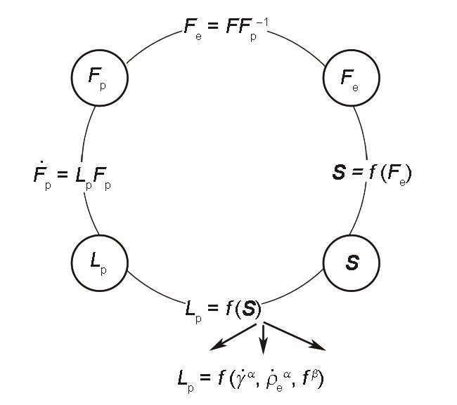
本工作采用图2所示的自洽方法求解如上所述的 F 及其内部相关变量[32]。首先由奥氏体晶粒的初始状态确定初始 Fp,之后再从总变形增量中去除塑性变形部分,计算 Fe。随后通过弹性变形Hooke定律计算 S。进一步将 S 作为诱导滑移和形变诱导相变的驱动力而发生塑性变形,由此便可计算一个时间步内的,同时获得下一个时间步的 Fp。再将计算所得的 Fp作为下一个时间步的初始塑性变形梯度,重复上述步骤持续迭代至变形结束,即可实现变形全过程的晶体塑性计算。本工作的建模和计算是在DAMASK软件理论框架下完成的[10]。
Fig.2
Self-consistent integration of kinematic quantities within fixed internal material state parameters ( F —deformation gradient, —tangent of plastic deformation gradient, Lp—velocity gradients of plastic deformation gradient, S —second Piola-Kirchhoff stress, —plastic slip rate, —evolution rate of edge dislocation, —martensite fraction)
S 是发生滑移和形变诱导相变这2种塑性变形的核心驱动力[10,18]。如图2所示,通过将 S 投影至各滑移系上,可以根据 式(13)及 式(17)计算塑性变形过程中各滑移系上的及;通过将 S 投影至等效相变系上,即可根据 式(25)计算变形过程中各等效相变系上形变诱导相变的分数。
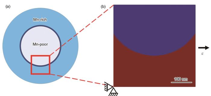
Fig.3
Geometric model of the Mn chemical boundary in austenite
(a) schematic of the chemical boundary
(b) representative volume element model (The red part represents the Mn-rich region with Mn content of 13% (mass fraction) and the blue part represents the Mn-poor region with Mn content of 5% (mass fraction). ε—strain)
Fig.4
Simulated microzone strain distributions across the chemical boundary within an austenite grain at strains of 0.025 (a), 0.05 (b), 0.075 (c), and 0.10 (d)
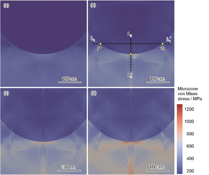
Fig.5
Simulated microzone stress distributions across the chemical boundary within an austenite grain at strains of 0.025 (a), 0.05 (b), 0.075 (c), and 0.1 (d)
Table 5
表5
表5奥氏体内部Mn化学界面两侧的微区应力及应变差统计值
Table 5 Statistics of the difference value of microzone strain and stress across the chemical boundary
ε
εmax - εmin
τmax - τmin / MPa
0.025
0.05 × 10⁻²
00.8
0.050
0.05 × 10⁻²
04.4
0.075
1.41 × 10⁻²
20.4
0.100
2.78 × 10⁻²
71.1
Note:εmax and εmin are the maximun and minumum strains within a single austenite grain, respectively; τmax and τmin are the maximun and minumum stresses within a single austenite grain, respectively
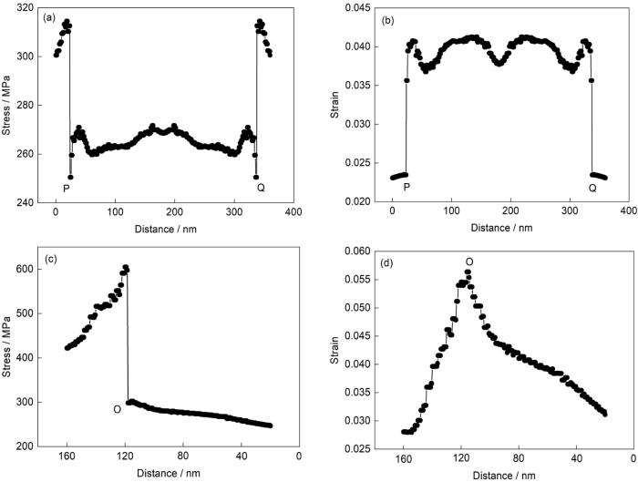
Fig.6
Microzone stress (a, c) and microzone strain (b, d) distributions along the lines L1-L (a, b) and L2-L (c, d) in Figs.4b and 5b at strain of 0.025
Fig.7
Simulated dislocation density distributions across the chemical boundary at strain of 0.1 (a) and profile of the dislocation density along the black line in Fig.7a (b)
Fig.8
Distribution of the martensite volume fraction at strain of 0.05 (a) and kinetics of the martensite transformation within austenite grain on both side of the chemical boundary during deformation (b)
Alloying is conventionally used for advancing properties of engineering materials. But with increasing degree of alloying, materials become more resource dependent and more costly, and recycling and reuse of materials become more difficult. As nowadays sustainability is becoming a more and more important index for materials development, novel strategies for sustainable materials development is highly desired. In this paper, a sustainable “plain” approach to advancing materials without changing chemical compositions is proposed, i.e., architecturing imperfections across different length-scales. Novel properties and performance can be achieved in the “plain” materials with less alloying or even non-alloying. Basic concept, principle, as well as potential applications of the “plain materials” approach will be introduced.
Strong and tough metallic materials are desired for light-weight structural applications in transportation and aerospace industries. Recently, heterostructures have been found to possess unprecedented strength-and-ductility synergy, which is until now considered impossible to achieve. Heterostructured metallic materials comprise heterogeneous zones with dramatic variations (> 100%) particularly in mechanical properties. The interaction in these hetero-zones produces a synergistic effect wherein the integrated property exceeds the prediction by the rule-of-mixtures. More importantly, the heterostructured materials can be produced by current industrial facilities at large scale and low cost. The superior properties of heterostructured materials are attributed to the heterodeformation induced (HDI) strengthening and strain hardening, which is produced by the piling-up of geometrically necessary dislocations (GNDs). These GNDs are needed to accommodate the strain gradient near hetero-zone boundaries, across which there is high mechanical incompatibility and strain partitioning. This paper classifies the types of heterostructures and delineates the deformation behavior and mechanisms of heterostructured materials.
Grain boundaries (GBs) are important planar defects in polycrystalline materials, and they are crucial in plastic deformation and recrystallization of materials. A fundamental understanding of GB deformation kinetics is critical for material design using GB engineering. Although GB dominated structural evolutions have been reported to proceed via different modes, the disconnection-based model has recently become a widely acknowledged approach to unify the GB dominated plasticity. In this paper, recent progresses of GB dominated plasticity in metallic materials based on disconnection-mediated GB migration have been reviewed. Disconnection dynamics, including nucleation, propagation and interactions between different disconnections, were found dominating the shear-coupled GB migration. Lateral motion of different GB disconnections contributes to the overall GB migration, during which dynamic interactions prevail. In the three-dimensional network of GBs, GB-defect interaction and triple junctions can further influence the shear-coupled GB migration by providing extra disconnection sources, which readily change the intrinsic disconnection dynamics. These disconnection-based GB kinetics are generally applicable in the migration of GBs with different structures, as well as other modes of GB dominated deformation. Based on the aforementioned, the effects of GB plasticity on mechanical properties and deformation of metallic materials are further discussed. This review provides a unified understanding of disconnection-based GB plasticity, which not only enriches mechanistic understanding of interface plasticity in metallic materials but also holds important implications for GB engineering toward advanced high-performance metallic materials.
DAMASK—The Düsseldorf advanced material simulation kit for modeling multi-physics crystal plasticity, thermal, and damage phenomena from the single crystal up to the component scale
Dislocation slip and twinning are the main deformation mechanisms dominating plastic behavior of crystalline materials, such as twinning-induced plasticity steel, Cu, Mg, and their alloys. The influence of twinning and interaction between dislocations and twins on the plastic deformation of crystal materials is complex. On the one hand, a sudden stress drop in the stress-strain curve during twin nucleation, propagation, and growth (TNPG) of crystal materials, i.e., the twinning softening effect, is evident. On the other hand, the interaction between twins and dislocations demonstrates the strengthening effect of plastic deformation. Polycrystalline materials are used in engineering applications, and twin nucleation corresponds to different strains in each grain. Therefore, determining the influence of twin softening and strengthening effects on plastic deformation of polycrystalline materials is difficult. In this work, a crystal plastic finite element model of Cu, considering the twinning softening effect, was developed to describe the TNPG process based on the crystal plasticity theory. The method was used to reveal the influence of twins' activation and their interaction with dislocations on strain hardening during the tension of Cu single crystal and polycrystal. The results show that twinning has an evident orientation effect. Under twinning favorable orientation, a sudden stress drop in the stress-strain curve caused by twinning propagation during plastic deformation of Cu single crystal is evident, and the total plastic deformation can be divided into three stages: slip, twinning, and interaction between dislocations and twins. Compared with Cu single crystal, the stress-strain curve changes smoothly and the strain hardening rate is higher during the tension of Cu polycrystal. Meanwhile, the dislocation density is concentrated at the grain boundary, and twins are easy to form at the grain boundary during the plastic deformation of Cu polycrystal.
Twinning induced plasticity (TWIP) steel exhibits high strength and exceptional plasticity due to the formation of extensive twin under mechanical load and its ultimate tensile strength and elongation to failure ductility-value can be as high as 5×10⁴ MPa%, which provide a new choice for automobile in developing the lightweight and improving safety. Generally, due to the texture was formed during process of plastic deformation, metal material appear anisotropic behavior. The deformation mechanisms, responsible for this high strain hardening, are related to the strain-induced microstructural changes, which was dominated by slip and twinning. Different deformation mechanisms, which can be activated at different stages of deformation, will strongly influence the stress strain response and the evolution of the microstructure. In this work, to predict the texture evolution under different loading conditions and understand these two deformation mechanisms of plastic deformation process, a polycrystal plasticity constitutive model of TWIP steel coupling slip and twinning was developed based on the crystal plasticity theory and single crystal plasticity constitutive model. A polycrystal homogenization method to keep geometry coordination and stress balance adjacent grains was used, which connected the state variables of single crystal and polycrystal. And then the model was implemented and programed based on the ABAQUS/UMAT platform. The texture evolution was obtained by EBSD at strain 0.27 and 0.60, respectively. The finite element models of tensile, compression and torsion processes were built by using the constitutive model. The mechanical response and texture evolution during plastic deformation process of TWIP steel were analyzed. The results show that with the increasing of the strain, the strain hardening phenomenon and texture density enhanced during the tensile process. Although texture types changed, texture density unchanged during the compression process. Owing to deformation increasing along the diameter direction, there is no obvious texture inside the cylinder when torsion deformation is small, texture emerged and enhanced gradually with the increasing of strain.
Near 50 years ago, transformation induced plasticity (TRIP) effect was proposed and TRIP steels as an advanced high strength one are widely investigated. However, the mechanism of TRIP effect can be only qualitatively explained, and has not been experimentally and theoretically verified so far. In this work, a strain equivalent model for strain-induced martensitic transformation was built in a microstructure-based finite element model of novel quenching-partitioning-tempering (Q-P-T) steel. With the model, the TRIP effect under the condition of uniaxial tension was simulated, from which the micro-mechanism of TRIP effect is revealed. Stress relaxation from TRIP relieves the stresses within untransformed retained austenite and its adjacent martensite and blocks the formation of cracks, meanwhile, a considerable retained austenite still exists at higher strain level, which is the origin of TRIP effect. Compared with original (thermal-induced) martensite, fresh (strain-induced) martensite bears higher stress. Therefore, it could be predicted that cracks form at first in fresh martensite or its boundaries. Moreover, stress relaxation makes strain-induced martensite formed in intermittent and slow way, and this is consistent with experimental results. However, in stress-free relaxation state fresh martensite appears in successive and quick way, not consistent with experiments, and thus this verifies in opposite way that TRIP effect inevitably produces stress relaxation.
Solving material mechanics and multiphysics problems of metals with complex microstructures using DAMASK—The Düsseldorf advanced material simulation kit
We revisit the meaning of stacking fault energy (SFE) and the assumptions of equilibrium dissociation of lattice dislocations in concentrated alloys. SFE is a unique value in pure metals. However, in alloys beyond the dilute limit, SFE has a distribution of values depending on the local atomic environment. Conventionally, the equilibrium distance between partial dislocations is determined by a balance between the repulsive elastic interaction between the partial dislocations and a unique value for SFE. This assumption is used to determine SFE from experimental measurements of dislocation splitting distances in metals and alloys, often contradicting computational predictions. We use atomistic simulations in a model NiCo alloy to study the dislocation dissociation process in a range of compositions with positive, zero, and negative average SFE and surprisingly observe a stable, finite splitting distance in all cases at low temperatures. We then compute the decorrelation stress and examine the balance of forces on the partial dislocations, considering the local effects on SFE, and observe that even the upper bound of SFE distribution alone cannot satisfy the force balance in some cases. Furthermore, we show that in concentrated solid solutions, the resisting force caused by interaction of dislocations with the local solute environment becomes a major force acting on partial dislocations. Here, we show that the presence of a high solute/dislocation interaction, which is not easy to measure and neglected in experimental measurements of SFE, renders the experimental values of SFE unreliable.
AshbyM F.
The deformation of plastically non-homogeneous materials
DAMASK—The Düsseldorf advanced material simulation kit for modeling multi-physics crystal plasticity, thermal, and damage phenomena from the single crystal up to the component scale
DAMASK: The Düsseldorf advanced material simulation kit for studying crystal plasticity using an Fe based or a spectral numerical solver
2
2012
... 在晶体塑性变形理论中,为了方便细观尺度本构建模,通常将晶体的弹性变形与塑性变形过程进行分解,如图1所示,将质点的变形分为3个构形:初始构形(即未变形态)、中间构形和当前构形(即变形态).进行变形梯度乘法分解时,晶粒首先从初始构形通过沿滑移面的塑性剪切变形至中间构形,再经刚性旋转变形至当前构形.晶体变形过程中,总变形梯度( F )可分解为弹性和塑性2部分[18]: ...
... S 是发生滑移和形变诱导相变这2种塑性变形的核心驱动力[10,18].如图2所示,通过将 S 投影至各滑移系上,可以根据 式(13)及 式(17)计算塑性变形过程中各滑移系上的及;通过将 S 投影至等效相变系上,即可根据 式(25)计算变形过程中各等效相变系上形变诱导相变的分数. ...
A molecular dynamics study of the fcc→bcc transformation at fault intersections
Solving material mechanics and multiphysics problems of metals with complex microstructures using DAMASK—The Düsseldorf advanced material simulation kit
1
2020
... 本工作采用图2所示的自洽方法求解如上所述的 F 及其内部相关变量[32].首先由奥氏体晶粒的初始状态确定初始 Fp,之后再从总变形增量中去除塑性变形部分,计算 Fe.随后通过弹性变形Hooke定律计算 S.进一步将 S 作为诱导滑移和形变诱导相变的驱动力而发生塑性变形,由此便可计算一个时间步内的,同时获得下一个时间步的 Fp.再将计算所得的 Fp作为下一个时间步的初始塑性变形梯度,重复上述步骤持续迭代至变形结束,即可实现变形全过程的晶体塑性计算.本工作的建模和计算是在DAMASK软件理论框架下完成的[10]. ...


