增材制造铝合金技术能够直接制备具有复杂结构的轻量化零件,且零件力学性能优异,在航空航天、汽车和轨道交通等领域应用广泛。其中,激光粉末床熔合(LPBF,又被称为选区激光熔化(SLM))技术最受关注[1 ,2 ] 。目前,增材制造领域中研究和应用最广泛的铝合金是Al-Si-Mg合金,这是由于它们具有良好的综合力学性能、出色的焊接性能及良好的抗热裂性和抗腐蚀性[1 ,3 ] 。
LPBF过程中的温度梯度极大,容易产生显著的残余应力[4 ] ,对零件的形状尺寸精度、服役安全性能和抗腐蚀性能等产生不利影响[3 ,5 ~7 ] ,因此在实际应用中,需要采用热处理(如去应力退火)等方法降低或消除残余应力[7 ] 。
目前,已有较多研究探讨了热处理制度对增材制造Al-Si-Mg合金微观结构和力学性能的影响。例如,Huang等[8 ] 发现,LPBF制备的AlSi10Mg合金在270℃去应力退火2 h后,Al-Si共晶网络部分断裂,Si相发生半球化,导致强度降低而延伸率提高。Takata等[9 ] 研究表明,LPBF制备的AlSi10Mg合金在300℃退火2 h后,屈服强度和拉伸强度分别由279和475 MPa降为180和285 MPa,延伸率由7.5%提高至18.6%。Chen等[10 ] 研究表明,LPBF制备的AlSi10Mg合金在280℃退火2 h后强度降低而延伸率提高,且力学性能各向异性明显降低。Zhang等[11 ] 研究发现,LPBF制备的AlSi10Mg合金在300℃退火2 h后,Al-Si共晶网络断裂,Si相球化,导致屈服强度、拉伸强度和疲劳强度均明显降低。Tridello等[12 ] 的研究指出,不同的退火温度会显著影响LPBF制备的AlSi10Mg合金的超高周疲劳性能,适当的退火处理(244℃退火2 h)能够保持共晶网络的完整性,从而提高合金的疲劳强度。这些研究表明了热处理制度在调控增材制造Al-Si-Mg合金性能中的重要作用。
尽管现有研究已涉及增材制造Al-Si-Mg合金的宏观力学性能和微观组织分析,但对其微观力学行为及其机制理解仍显不足。同步辐射X射线衍射(XRD)和中子衍射原位变形实验技术能够更精确地分析金属材料在变形过程中的微观力学参量变化,从而为理解材料变形行为和力学性能提供新的、深刻的见解。Xie等[13 ] 采用中子衍射原位循环变形实验揭示了6061铝合金的变形诱导损伤各向异性,探测到了晶体取向相关的晶格应变行为。本课题组[14 ] 前期采用同步辐射XRD原位变形实验分析了增材制造AlSi10Mg打印态合金的晶格应变、相应力和位错密度演化行为,发现Si相存在庞载荷传递效应(giant load transfer effect),Si相最大晶格应变高达约12000 × 10-6 ,约为铸造合金对应值的4倍,对合金力学行为有显著影响;同时还发现了多级位错强化行为。随后,Takata等[15 ] 采用同步辐射XRD原位变形实验分析了增材制造Al-12%Si (质量分数)打印态和300℃、2 h退火态及530℃、6 h退火态合金的晶格应变、相应力和位错密度演化行为。Li等[16 ] 也采用同步辐射XRD原位变形实验分析了增材制造AlSi10Mg打印态合金的晶格应变和相应力演化行为。目前,增材制造AlSi10Mg合金在退火后的晶格应变、应力和位错密度演化行为还需进一步研究。
值得注意的是,Takata等[15 ] 在分析位错密度时采用了传统Williamson-Hall (WH)方法,分析结果显示打印态和300℃、2 h退火态试样的初始位错密度非常接近,这与实验观察结果不相符[10 ] ;打印态合金在3%应变左右时位错密度明显降低,但并未对此给出合理解释;而后位错密度又增大,9%应变时,打印态和300℃、2 h退火态试样的位错密度也仅相差约20%,这些结果难以解释打印态和300℃、2 h退火态试样在加工硬化率上的显著差异[15 ] 。这应该与传统WH方法的局限性相关,导致位错密度分析误差较大。
为了提高位错密度分析的准确性,可以联合修正的Williamson-Hall (mWH)方法与修正的Warren-Averbach (mWA)方法[17 ,18 ] ,或者采用近年新发展的卷积多重全型(convolutional multiple whole profile,CMWP)方法[19 ] 。这些方法都考虑了衍射峰宽化的各向异性行为,并对衍射峰线型进行了整体考虑,而不仅仅是半高宽,从而能够更精确地分析位错密度。
本工作基于同步辐射XRD原位变形实验技术,对LPBF垂直制备的AlSi10Mg打印态和退火态合金进行了分析,探讨合金变形过程中的晶格应变与相应力,同时采用CMWP方法量化了位错密度的演化。通过对加工硬化行为进行对比分析,阐明了退火热处理对载荷传递行为与位错行为的影响,旨在为建立精确的力学性能预测模型(如晶体塑性模型)提供参考依据。
1 实验方法
1.1 材料制备
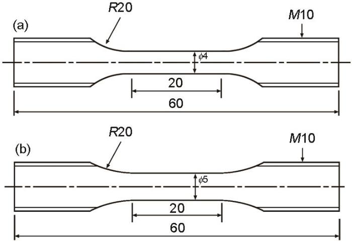
AlSi10Mg合金棒状试样由LPBF方法垂直打印(这与前期研究[14 ] 不同(其试样为水平打印方式)),所用设备为Concept Laser M2 cusing激光系统,实验激光参数[14 ] 为:激光功率370 W,激光直径150 μm,激光扫描速率1500 mm/s,层厚30 μm,基板未预热。垂直打印样品分为2部分,一部分保持打印态,不进行热处理,通过机械加工制成哑铃型棒状试样,试样总长60 mm,平行段长度20 mm、直径4 mm,见图1a ;另一部分样品在270℃去应力退火2 h,再机械加工成哑铃状棒型试样,试样总长60 mm,平行段长度20 mm、直径5 mm,见图1b 。虽然打印态试样与去应力退火试样的平行段直径有所不同,但并不影响对实验结果的分析。
图1
图1
原位变形实验试样尺寸
Fig.1
Sample dimensions for the in situ deformation experiment (unit: mm)
(a) as-printed sample
(b) stress-relieved annealed sample
1.2 微观组织观察
打印态和去应力退火态试样经机械研磨和抛光后,采用Thermo Fischer Quattro S型扫描电镜(SEM)观察试样的微观组织。为了获得最佳的物相和晶粒取向对比,使用了圆形背散射电子探测器。对于2500放大倍数,所使用的电压为4.0 kV,电子束斑尺寸6.0,光圈直径20 μm;对于15000放大倍数,所使用的电压为10.0 kV,电子束斑尺寸4.0,光圈直径20 μm。
1.3 同步辐射X 射线衍射原位拉伸变形实验
在DESY PETRA III光源的P07B线站(由亥姆霍兹联合会运行)开展同步辐射XRD原位拉伸变形实验。拉伸变形过程通过位移控制,拉伸速率0.3 mm/min,相当于2.5 × 10-4 s-1 的名义应变速率。试样平行段应变由Instron 2620-602型引伸计测量。同步辐射X射线能量为87.1 keV,X射线波长0.014235 nm,光束尺寸0.7 mm × 0.7 mm。面探测器型号为PerkinElmer XRD 1622。二维衍射图的180° ± 5°和270° ± 5°分区分别用于计算横向(TD)和加载方向(LD)的衍射强度-2θ 曲线。
1.4 晶格应变、应力与位错密度分析
s 方向(s 为LD或TD)的{hkl }晶格应变ε h k l i , s i 为Al或Si相)由下式计算[14 ] :
ε h k l i , s = s i n θ h k l , 0 i , s s i n θ h k l i , s - 1 (1)
式中,θ h k l i , s [14 ] 。需要指出的是,由于采用的是未加载状态作为参考状态,因此所计算的晶格应变/应力结果仅反映对外部加载条件的力学响应,不反映残余应变/应力或绝对应变/应力[14 ] 。
由衍射峰拟合误差所带来的晶格应变误差u ε , h k l i , s [14 ] :
u ε , h k l i , s = c o s θ h k l , 0 i , s s i n θ h k l i , s δ θ h k l , 0 i , s 2 + c o s θ h k l i , s s i n θ h k l , 0 i , s s i n 2 θ h k l i , s δ θ h k l i , s 2 1 / 2 (2)
式中,δ θ h k l , 0 i , s δ θ h k l i , s θ h k l , 0 i , s θ h k l i , s
采用CMWP方法分析位错密度。在CMWP方法中,物理线型函数通过尺寸宽化和微观应变宽化函数的卷积计算获得,均方应变ε 2 [20 ] :
ε 2 = ρ C ¯ b 4 π f η (3)
式中,ρ C ¯ b 为位错的Burgers矢量模,f η
2 实验结果和分析讨论
2.1 宏观力学性能
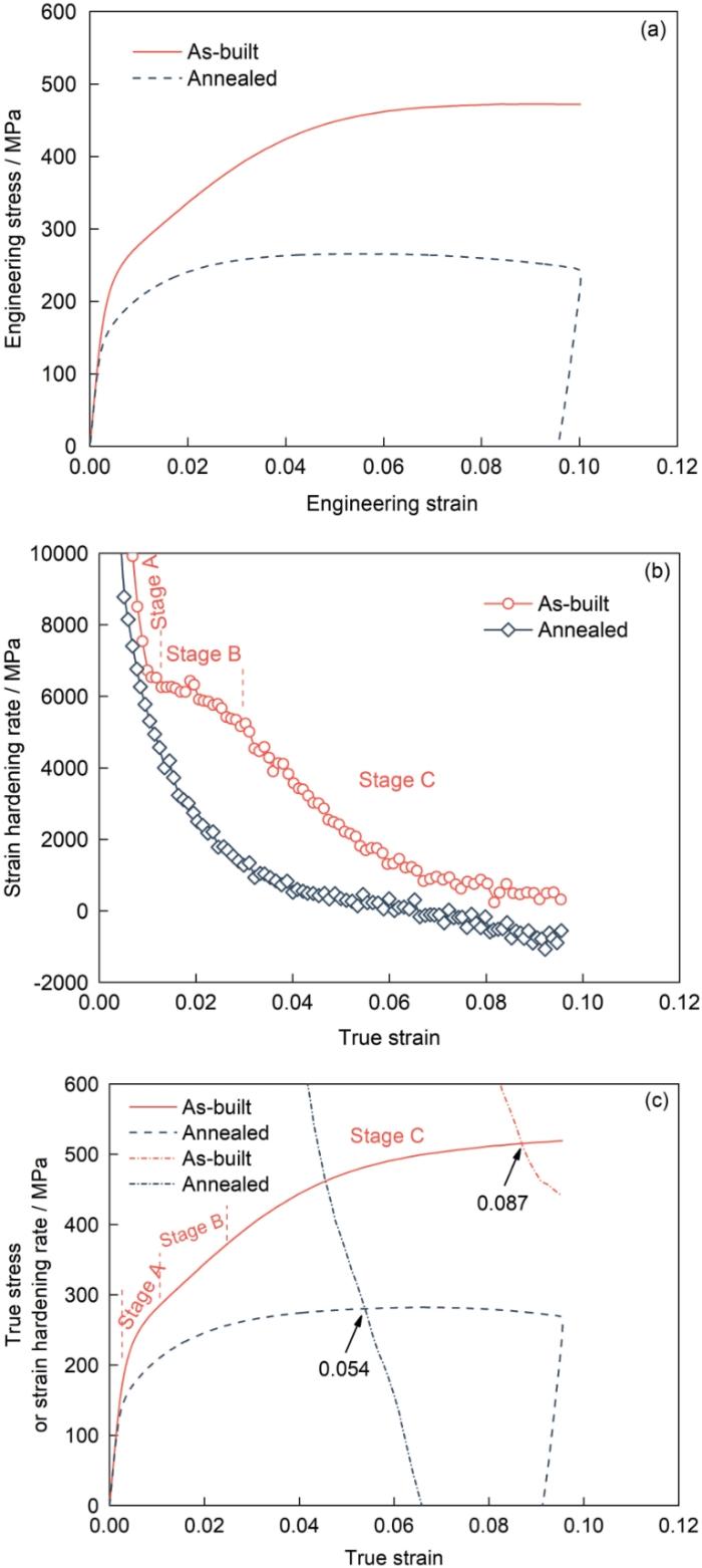
图2a 显示了打印态和退火态试样的宏观拉伸曲线。其中,打印态试样拉伸至断裂,断裂时工程应变为0.10;退火态试样拉伸至0.10工程应变后卸载。图2b 显示了试样的加工硬化率曲线。图2 表明,打印态试样的塑性变形行为可以分为3个阶段,分别记为A、B和C阶段。阶段A的加工硬化率非常高,但随应变增加而快速降低;阶段B的加工硬化率变化很小,约为6000 MPa,因此阶段B的真应力-应变曲线近似为直线;阶段C的加工硬化率随着应变增大而逐步减小,当真应变大于0.07后,加工硬化率趋于定值。退火态试样的加工硬化率随着应变增加持续平滑减小。上述结果表明,退火后,宏观力学行为的改变不仅体现在强度降低和加工硬化率降低方面,加工硬化率的演化路径形态也发生了改变。这些变化与微观结构和微观力学行为的改变有关。
图2
图2
打印态和退火态试样的宏观力学行为
Fig.2
Macroscopic behaviors of as-built and annealed samples
(a) engineering stress-strain curves
(b) hardening coefficient curves
(c) determination of uniform true strain
根据Considère颈缩判据d σ t r u e / d ε t r u e = σ t r u e σ t r u e ε t r u e 图2c 。当应变超过均匀真应变后,材料发生颈缩,即产生局部变形。因此,在后续的衍射数据分析时,只对均匀真应变以前的数据进行分析,即针对均匀变形阶段。
2.2 微观组织
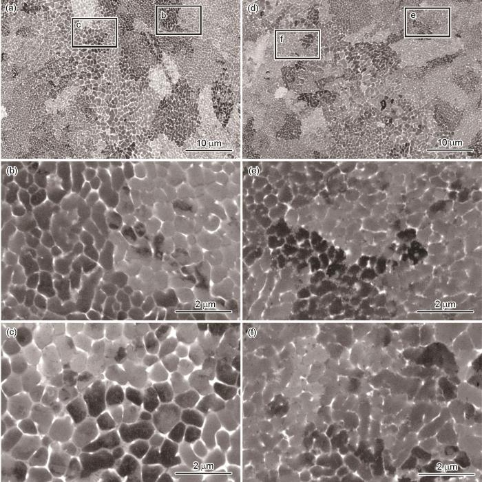
图3a ~c 所示为打印态试样显微组织的SEM像,可以看到完整的Al-Si共晶网络。图3a 和d 还显示出Al基体不同亚晶的衬度差别,熔池边界处的晶胞尺寸大于熔池内部。图3b 和c 分别为打印态试样熔池内部和熔池边界处显微组织的高倍SEM像,显示Al-Si共晶网络连续且清晰。而图3e 和f 显示,经过270℃去应力退火2 h后,退火态试样Al-Si共晶网络已被部分破坏,Al-Si共晶网络不再连续,Si相发生球化,这些变化与文献报道[3 ,8 ,9 ] 吻合。
图3
图3
打印态试样和退火态试样显微组织的SEM像
Fig.3
SEM images of microstructures of as-built (a-c) and annealed (d-f) samples
(a, d) microstructures at low magnification
(b, e) microstructures within the melt-pool
(c, f) microstructures on the melt-pool boundary
2.3 晶格应变与应力演化
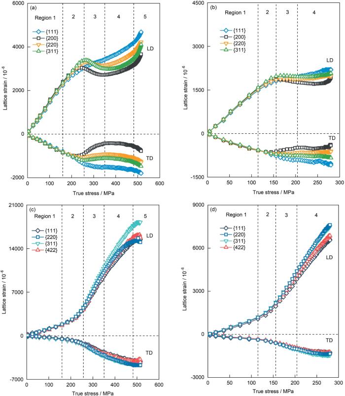
图4 展示了打印态和退火态试样的{hkl }晶格应变演化,其中,图4a 和b 为Al基体,图4c 和d 为Si相。晶格应变的最大误差列在表1 中。晶格应变的最大误差是指在整个变形过程中各{hkl }晶格应变误差的最大值,变形过程中的晶格应变误差小于等于该值。
图4
图4
打印态和退火态试样Al基体和Si相的{hkl }晶格应变演化
Fig.4
Evolutions of lattice strains of as-built (a, c) and annealed (b, d) samples (LD—loading direction, TD—transverse direction)
(a, b) Al matrix (c, d) Si phase
根据图4a 和c ,打印态试样Al、Si两相的晶格应变演化可细分为5个阶段。
(1) 阶段1为纯弹性变形阶段:在这一阶段,Al、Si两相的{hkl }晶格应变随着加载应力的增加而线性变化。
(2) 阶段2为弹塑性转变前期:此时,Al基体开始出现塑性变形,虽然程度很小,但已导致晶格应变曲线略微偏离了原有的直线轨迹。同时,由于Al基体的塑性变形,载荷传递作用使得Si相在加载方向上的晶格应变开始加速增大。
(3) 阶段3为弹塑性转变后期:在这个阶段,Al基体的各个晶面已经发生了明显的塑性变形,晶格应变曲线显著偏离直线。其中Al{111}晶面表现出加工硬化的特性,而Al{200}、{220}和{311}晶面则呈现出加工软化的特征。同时,Si相在加载方向上的各晶格应变几乎是线性且迅速地增加。
(4) 阶段4为宏观塑性变形阶段:此阶段,Al基体中的所有晶格应变均显示出加工硬化的特征,而Si相在加载方向上的各晶格应变则继续保持快速增长。
(5) 阶段5为损伤阶段:在这一阶段,Si相在加载方向上的晶格应变缓慢增加,随后开始下降。这是由于Si相的损伤导致其承载能力减弱,部分载荷因此转移到Al基体上,使得Al基体中的各晶格应变随着加载应力的增加而迅速上升。
如图4b 和d 所示,去应力退火显著改变了增材制造AlSi10Mg合金的微观力学特性,具体表现在以下几个方面。
(1) 在阶段3,退火态试样在加载方向上的Al{200}、{220}和{311}晶面虽然也表现出加工软化现象,但晶格应变的降低幅度相对较小。
(2) 在阶段4,退火态试样在加载方向上的Al{111}与{200}晶格应变最大差异约为444 × 10-6 ,远小于打印态试样的1047 × 10-6 。这表明退火处理有助于缓解Al基体晶粒尺度的塑性变形各向异性。
(3) 值得注意的是,退火态试样在加载方向上的Si相最大晶格应变出现在{220}晶面,为7619 × 10-6 。相比之下,打印态试样的最大晶格应变出现在Si的{311}晶面,高达18267 × 10-6 ,是退火态试样的2倍以上。这种差异可能与退火过程中Si相球化有关,退火改变了Si相的形态、尺寸和晶体取向,进而影响其微观力学行为。
(4) 退火态试样的Si相晶格应变未出现损伤阶段,这与其较小的晶格应变有关。退火导致Al基体发生回复,降低了其强度,使得流变应力偏低,不足以支撑足够强的载荷传递效应。因此,退火态试样中Si相承受的最大载荷小于打印态,未达到引发损伤所需的临界载荷。
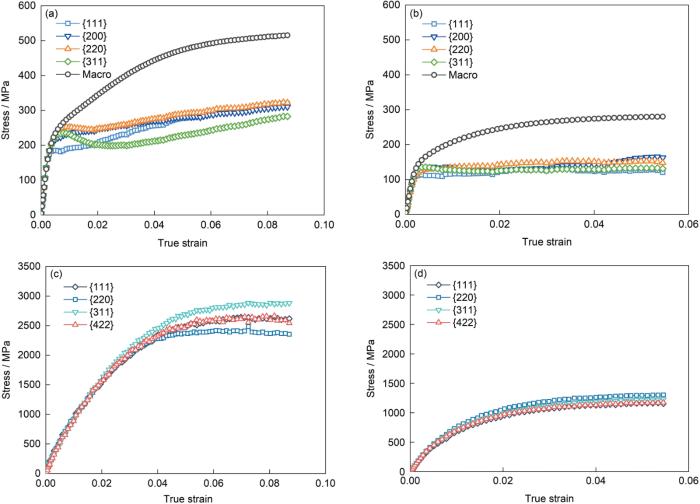
根据晶格应变和Hook定律可以计算出Al和Si两相中不同{hkl }晶格的应力,如图5 所示。图5a 和b 比较了Al基体中各{hkl }晶格应力与合金的宏观应力。可以看出,在弹性变形阶段,Al基体的应力与宏观应力基本一致;而进入塑性变形阶段,合金的宏观应力明显大于Al基体中的应力,这一差异主要由Si相应力所引起。图5c 和d 表明,在均匀变形阶段,打印态和退火态合金中Si{311}晶格应力最大值分别达到了2885和1224 MPa。前者远远超过了前期研究结果[14 ,21 ,22 ] 所报道的数值,在前期研究中,LPBF水平打印的AlSi10Mg合金中Si{311}晶格应力的最大值约为1948 MPa (此时合金宏观真应变为0.058)[14 ] ,而LPBF垂直打印的AlSi3.5Mg2.5合金中Si{311}晶格应力的最大值约为2363 MPa (此时合金宏观真应变为0.090)[21 ] 。通过对比分析,并结合图5c 和d 结果,推断Si相中的最大应力与合金塑性密切相关:合金的应变越大,Si相应力也随之增大[23 ] 。
图5
图5
打印态退火态样品Al基体和Si相的不同{hkl }晶格的应力演化
Fig.5
Evolutions of phase stresses of as-built (a, c) and annealed (b, d) samples
(a, b) Al matrix (c, d) Si phase
考虑到AlSi10Mg合金中Si相的体积含量约为9.63%[14 ] ,可以推算出,在打印态和退火态合金中,Si相对最大载荷的贡献率分别为2885 × 9.63% ÷ 505 = 55%和1224 × 9.63% ÷ 280 = 42%,其中,505和280 MPa分别是打印态和退火态合金中Si相Si{311}晶格应力最大时所对应的合金宏观真应力。该结果揭示了Si相的庞载荷传递强化效应,即仅仅以9.63%的体积分数,便能分别承担高达55%和42%的外加载荷。
2.4 位错密度演化
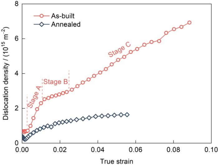
位错密度演化的分析结果见图6 。在开始变形前,打印态和退火态合金中的Al基体位错密度分别为6.83 × 10¹⁴ 和3.85 × 10¹⁴ m-2 。在塑性变形阶段,打印态合金中Al基体的位错密度变化可分为3个阶段,这与图2 中划分的3个阶段相吻合。因此,可以推测位错密度的这种阶段性演化是导致打印态合金加工硬化行为呈现三阶段特征的根本原因。具体来说,阶段A的位错密度迅速上升,阶段B增长放缓,而到了阶段C,位错密度再次以较快的速度增加。对于退火态合金,随着宏观应变的增加,Al基体的位错密度最初增长较快,但随后增速逐渐放缓。在整个加载变形过程中,位错密度的变化相对平稳。在均匀变形阶段,打印态和退火态合金中Al基体的位错密度最大值分别为6.92 × 10¹⁵ 和1.63 × 10¹⁵ m-2 。
图6
图6
打印态和退火态合金中Al基体的位错密度演化
Fig.6
Dislocation density evolutions of Al matrix of as-built and annealed samples
2.5 去应力退火对合金变形行为的影响
2.5.1 退火前后Al和Si相对合金加工硬化率的贡献
合金在加载方向的宏观应力σ L D m a c r o [14 ,24 ] :
σ L D m a c r o = 1 - f S i σ A l , L D + f S i σ S i , L D (4)
式中,σ A l , L D σ S i , L D f S i 图4a 和b )均出现了加工软化行为,如果用Al{311}晶格应变/应力代表打印态合金中Al基体的整体行为,则根据载荷传递效应,Si相中的晶格应变/应力也应该跟随下降,实际情况是在阶段3,打印态和退火态合金及其Si相均表现为加工硬化行为,因此在这里选择Al{111}晶格应变/应力代表合金中Al基体的整体行为。根据 式(3),合金的加工硬化率d σ L D m a c r o / d ε m a c r o
d σ L D m a c r o d ε m a c r o = 1 - f S i d σ A l , L D d ε m a c r o + f S i d σ S i , L D d ε m a c r o (5)
式中,ε m a c r o 1 - f S i d σ A l , L D / d ε m a c r o f S i d σ S i , L D / d ε m a c r o
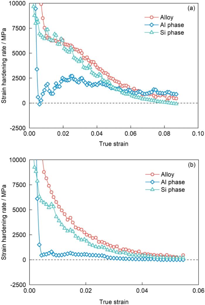
根据 式(5)计算的Al和Si两相对合金加工硬化率的贡献如图7 所示。图7a 表明,对于打印态合金,当宏观真应变在0.005~0.050区间时,Si相贡献的加工硬化率占主导;当宏观真应变大于0.050后,Al基体的加工硬化率占主导;当宏观真应变大于0.084后,Si相损伤使其加工硬化率转为负值,而合金和Al基体的加工硬化率仍为正值。图7b 表明,对于退火态合金,在整个均匀塑性变形阶段,Si相贡献的加工硬化率占主导。
图7
图7
Al和Si两相对合金加工硬化率的贡献(这里重新绘制了图2b中的合金数据用于对比)
Fig.7
Contributions of Al and Si phases to the strain hardening rate of the alloys (The data of alloys in Fig.2b was plotted here again for comparison)
(a) as-built sample (b) annealed sample
2.5.2 退火热处理对位错行为的影响
图6 表明去应力退火处理显著降低了合金的初始位错密度,这个结果与Chen等[10 ] 的电子背散射衍射(EBSD)观察结果一致:增材制造AlSi10Mg合金在280℃退火2 h后,核平均取向差(KAM)减小,证实了位错密度的降低。同时,变形过程中的位错密度演化表明,退火态合金的位错密度增长率远低于打印态合金,这与前期研究[25 ] 中位错密度的演化趋势相符:前期对增材制造AlSi3.5Mg2.5合金的研究表明,直接时效态和退火态AlSi3.5Mg2.5合金的初始位错密度分别为6.00 × 10¹⁴ 和1.40 × 10¹⁴ m-2 ;变形5.7%后,位错密度分别增加到2.47 × 10¹⁵ 和3.22 × 10¹⁴ m-2 。
此外,可以看到,打印态合金的位错密度演化路径也有明显差别,打印态合金表现出多级特性,这与前期研究结果[14 ,21 ,26 ,27 ] 类似,即增材制造合金表现出了多级位错强化行为,该行为与增材制造所形成的Al-Si共晶网络对位错运动的强烈阻碍作用有关。退火热处理后,Al-Si共晶网络出现局部断裂,Si相发生部分球化,对位错的阻碍作用降低,因此位错密度演化曲线较为平滑[21 ] 。
3 结论
(1) LPBF制备的AlSi10Mg打印态合金的加工硬化率可分为3个阶段:阶段A的加工硬化率非常高,但随应变增加而快速降低;阶段B的加工硬化率变化很小;阶段C的加工硬化率随着应变增大而逐步减小。LPBF制备的AlSi10Mg合金在270℃退火2 h后,强度和加工硬化率均降低,且加工硬化率随应变呈光滑连续降低。微观结构方面,退火态合金中Al-Si共晶网络局部断裂,Si相发生球化,且Al基体发生了回复,位错密度降低。
(2) AlSi10Mg打印态合金的Al、Si 2相的晶格应变演化可细分为5个阶段:纯弹性变形阶段、弹塑性转变前期、弹塑性转变后期、宏观塑性变形阶段和损伤阶段。对于AlSi10Mg退火态合金,Al、Si两相在加载阶段的晶格应变演化可细分为4个阶段:纯弹性变形阶段、弹塑性转变前期、弹塑性转变后期和宏观塑性变形阶段。
(3) Al{111}晶格应变的演化行为与宏观变形行为最接近,且其残余晶格应变最小,因此用Al{111}晶格应变/应力代表Al基体的整体行为比Al{311}更合适。均匀变形阶段,打印态和退火态合金中Si{311}晶格应力最大值分别达到了2885和1224 MPa,表明Si相产生了庞载荷传递强化效应。对加工硬化率的分析表明,无论是打印态合金还是退火态合金,在塑性变形前期,Si相对加工硬化率的贡献均占主导。
(4) 打印态合金的位错密度演化分为3个阶段:阶段A的位错密度迅速上升;阶段B增长放缓;而到了阶段C,位错密度再次以较快的速度增加。对于退火态合金,Al-Si共晶网络出现局部断裂,Si相发生部分球化,对位错的阻碍作用降低,随着宏观应变的增加,Al基体的位错密度最初增长较快,但随后增速逐渐放缓。
参考文献
View Option
[1]
Aboulkhair N T Simonelli M Parry L et al 3D printing of aluminium alloys: Additive manufacturing of aluminium alloys using selective laser melting
[J]. Prog. Mater Sci. , 2019 , 106 : 100578
[本文引用: 2]
[2]
Martin J H Yahata B D Hundley J M et al 3D printing of high-strength aluminium alloys
[J]. Nature , 2017 , 549 : 365
[本文引用: 1]
[3]
Fiocchi J Tuissi A Biffi C A Heat treatment of aluminium alloys produced by laser powder bed fusion: A review
[J]. Mater. Des. , 2021 , 204 : 109651
[本文引用: 3]
[4]
Zhao L Macías J G S Dolimont A et al Comparison of residual stresses obtained by the crack compliance method for parts produced by different metal additive manufacturing techniques and after friction stir processing
[J]. Addit. Manuf. , 2020 , 36 : 101499
[本文引用: 1]
[5]
Schröder J Evans A Mishurova T et al Diffraction-based residual stress characterization in laser additive manufacturing of metals
[J]. Metals , 2021 , 11 : 1830
[本文引用: 1]
[6]
Fang Z C Wu Z L Huang C G et al Review on residual stress in selective laser melting additive manufacturing of alloy parts
[J]. Opt. Laser Technol. , 2020 , 129 : 106283
[7]
Laleh M Sadeghi E Revilla R I et al Heat treatment for metal additive manufacturing
[J]. Prog. Mater Sci. , 2023 , 133 : 101051
[本文引用: 2]
[8]
Huang N Luo Q X Bartles D L et al Effect of heat treatment on microstructure and mechanical properties of AlSi10Mg fabricated using laser powder bed fusion
[J]. Mater. Sci. Eng. , 2024 , A895 : 146228
[本文引用: 2]
[9]
Takata N Kodaira H Sekizawa K et al Change in microstructure of selectively laser melted AlSi10Mg alloy with heat treatments
[J]. Mater. Sci. Eng. , 2017 , A704 : 218
[本文引用: 2]
[10]
Chen S Q Tan Q Y Gao W Q et al Effect of heat treatment on the anisotropy in mechanical properties of selective laser melted AlSi10Mg
[J]. Mater. Sci. Eng. , 2022 , A858 : 144130
[本文引用: 3]
[11]
Zhang C C Zhu H H Liao H L et al Effect of heat treatments on fatigue property of selective laser melting AlSi10Mg
[J]. Int. J. Fatigue , 2018 , 116 : 513
[本文引用: 1]
[12]
Tridello A Fiocchi J Biffi C A et al Influence of the annealing and defects on the VHCF behavior of an SLM AlSi10Mg alloy
[J]. Fatigue Fract. Eng. Mater. Struct. , 2019 , 42 : 2794
[本文引用: 1]
[13]
Xie Q G Lian J H Sidor J J et al Crystallographic orientation and spatially resolved damage in a dispersion-hardened Al alloy
[J]. Acta Mater. , 2020 , 193 : 138
[本文引用: 1]
[14]
Zhang X X Lutz A Andrä H et al Evolution of microscopic strains, stresses, and dislocation density during in-situ tensile loading of additively manufactured AlSi10Mg alloy
[J]. Int. J. Plast. , 2021 , 139 : 102946
[本文引用: 12]
[15]
Takata N Liu M L Hirata M et al Microstructural origins of high strength of Al-Si alloy manufactured by laser powder bed fusion: In-situ synchrotron radiation X-ray diffraction approach
[J]. J. Mater. Sci. Technol. , 2024 , 178 : 80
[本文引用: 3]
[16]
Li C Zhang W X Yang H O et al Microstructural origin of high strength and high strain hardening capability of a laser powder bed fused AlSi10Mg alloy
[J]. J. Mater. Sci. Technol. , 2024 , 197 : 194
[本文引用: 1]
[17]
Hong Y Y Gao J Liu X Q et al Investigation of the high-temperature fatigue mechanism related to altered local short-range order in AL6XN austenitic stainless steel
[J]. Mater. Des. , 2023 , 236 : 112504
[本文引用: 1]
[18]
Masumura T Inami K Matsuda K et al Quantitative evaluation of dislocation density in as-quenched martensite with tetragonality by X-ray line profile analysis in a medium-carbon steel
[J]. Acta Mater. , 2022 , 234 : 118052
[本文引用: 1]
[19]
Ribárik G Jóni B Ungár T Global optimum of microstructure parameters in the CMWP line-profile-analysis method by combining Marquardt-Levenberg and Monte-Carlo procedures
[J]. J. Mater. Sci. Technol. , 2019 , 35 : 1508
DOI
[本文引用: 1]
Line profile analysis of X-ray and neutron diffraction patterns is a powerful tool for determining the microstructure of crystalline materials. The Convolutional-Multiple-Whole-Profile (CMWP) procedure is based on physical profile functions for dislocations, domain size, stacking faults and twin boundaries. Order dependence, strain anisotropy, hkl dependent broadening of planar defects and peak shape are used to separate the effect of different lattice defect types. The Marquardt-Levenberg (ML) numerical optimization procedure has been used successfully to determine crystal defect types and densities. However, in more complex cases like hexagonal materials or multiple phases the ML procedure alone reveals uncertainties. In a new approach the ML and a Monte-Carlo statistical method are combined in an alternative manner. The new CMWP procedure eliminates uncertainties and provides globally optimized parameters of the microstructure.
[20]
Zhang X X Bauer P P Lutz A et al Microplasticity and macroplasticity behavior of additively manufactured Al-Mg-Sc-Zr alloys: In-situ experiment and modeling
[J]. Int. J. Plast. , 2023 , 166 : 103659
[本文引用: 1]
[21]
Zhang X X Lutz A Andrä H et al An additively manufactured and direct-aged AlSi3.5Mg2.5 alloy with superior strength and ductility: Micromechanical mechanisms
[J]. Int. J. Plast. , 2021 , 146 : 103083
[本文引用: 4]
[22]
Li Y Yu J Y Li S L et al The influence of post-aging treatment on the microstructure and micromechanical behaviors of additively manufactured maraging steel investigated by in situ high-energy X-ray diffraction
[J]. J. Mater. Sci. Technol. , 2024 , 200 : 1
[本文引用: 1]
[23]
Zhang X X Knoop D Andrä H et al Multiscale constitutive modeling of additively manufactured Al-Si-Mg alloys based on measured phase stresses and dislocation density
[J]. Int. J. Plast. , 2021 , 140 : 102972
[本文引用: 1]
[24]
Harjo S Tsuchida N Abe J et al Martensite phase stress and the strengthening mechanism in TRIP steel by neutron diffraction
[J]. Sci. Rep. , 2017 , 7 : 15149
DOI
PMID
[本文引用: 1]
Two TRIP-aided multiphase steels with different carbon contents (0.2 and 0.4 mass%) were analyzed in situ during tensile deformation by time-of-flight neutron diffraction to clarify the deformation induced martensitic transformation behavior and its role on the strengthening mechanism. The difference in the carbon content affected mainly the difference in the phase fractions before deformation, where the higher carbon content increased the phase fraction of retained austenite (γ). However, the changes in the relative fraction of martensitic transformation with respect to the applied strain were found to be similar in both steels since the carbon concentrations in γ were similar regardless of different carbon contents. The phase stress of martensite was found much larger than that of γ or bainitic ferrite since the martensite was generated at the beginning of plastic deformation. Stress contributions to the flow stress were evaluated by multiplying the phase stresses and their phase fractions. The stress contribution from martensite was observed increasing during plastic deformation while that from bainitic ferrite hardly changing and that from γ decreasing.
[25]
Zhang X X Lutz A Andrä H et al Strain hardening behavior of additively manufactured and annealed AlSi3.5Mg2.5 alloy
[J]. J. Alloys Compd. , 2022 , 898 : 162890
[本文引用: 1]
[26]
Santos Macías J G Douillard T Zhao L et al Influence on microstructure, strength and ductility of build platform temperature during laser powder bed fusion of AlSi10Mg
[J]. Acta Mater. , 2020 , 201 : 231
[本文引用: 1]
[27]
Dan C Y Cui Y C Wu Y et al Achieving ultrahigh fatigue resistance in AlSi10Mg alloy by additive manufacturing
[J]. Nat. Mater. , 2023 , 22 : 1182
DOI
PMID
[本文引用: 1]
Since the first discovery of the fatigue phenomenon in the late 1830s, efforts to fight against fatigue failure have continued. Here we report a fatigue resistance phenomenon in nano-TiB-decorated AlSi10Mg enabled by additive manufacturing. This fatigue resistance mechanism benefits from the three-dimensional dual-phase cellular nanostructure, which acts as a strong volumetric nanocage to prevent localized damage accumulation, thus inhibiting fatigue crack initiation. The intrinsic fatigue strength limit of nano-TiB-decorated AlSi10Mg was proven to be close to its tensile strength through the in situ fatigue tests of a defect-free microsample. To demonstrate the practical applicability of this mechanism, printed bulk nano-TiB-decorated AlSi10Mg achieved fatigue resistance more than double those of other additive manufacturing Al alloys and surpassed those of high-strength wrought Al alloys. This strategy of additive-manufacturing-assisted nanostructure engineering can be extended to the development of other dual-phase fatigue-resistant metals.© 2023. The Author(s), under exclusive licence to Springer Nature Limited.
3D printing of aluminium alloys: Additive manufacturing of aluminium alloys using selective laser melting
2
2019
... 增材制造铝合金技术能够直接制备具有复杂结构的轻量化零件,且零件力学性能优异,在航空航天、汽车和轨道交通等领域应用广泛.其中,激光粉末床熔合(LPBF,又被称为选区激光熔化(SLM))技术最受关注[1 ,2 ] .目前,增材制造领域中研究和应用最广泛的铝合金是Al-Si-Mg合金,这是由于它们具有良好的综合力学性能、出色的焊接性能及良好的抗热裂性和抗腐蚀性[1 ,3 ] . ...
... [1 ,3 ]. ...
3D printing of high-strength aluminium alloys
1
2017
... 增材制造铝合金技术能够直接制备具有复杂结构的轻量化零件,且零件力学性能优异,在航空航天、汽车和轨道交通等领域应用广泛.其中,激光粉末床熔合(LPBF,又被称为选区激光熔化(SLM))技术最受关注[1 ,2 ] .目前,增材制造领域中研究和应用最广泛的铝合金是Al-Si-Mg合金,这是由于它们具有良好的综合力学性能、出色的焊接性能及良好的抗热裂性和抗腐蚀性[1 ,3 ] . ...
Heat treatment of aluminium alloys produced by laser powder bed fusion: A review
3
2021
... 增材制造铝合金技术能够直接制备具有复杂结构的轻量化零件,且零件力学性能优异,在航空航天、汽车和轨道交通等领域应用广泛.其中,激光粉末床熔合(LPBF,又被称为选区激光熔化(SLM))技术最受关注[1 ,2 ] .目前,增材制造领域中研究和应用最广泛的铝合金是Al-Si-Mg合金,这是由于它们具有良好的综合力学性能、出色的焊接性能及良好的抗热裂性和抗腐蚀性[1 ,3 ] . ...
... LPBF过程中的温度梯度极大,容易产生显著的残余应力[4 ] ,对零件的形状尺寸精度、服役安全性能和抗腐蚀性能等产生不利影响[3 ,5 ~7 ] ,因此在实际应用中,需要采用热处理(如去应力退火)等方法降低或消除残余应力[7 ] . ...
... 图3a ~c 所示为打印态试样显微组织的SEM像,可以看到完整的Al-Si共晶网络.图3a 和d 还显示出Al基体不同亚晶的衬度差别,熔池边界处的晶胞尺寸大于熔池内部.图3b 和c 分别为打印态试样熔池内部和熔池边界处显微组织的高倍SEM像,显示Al-Si共晶网络连续且清晰.而图3e 和f 显示,经过270℃去应力退火2 h后,退火态试样Al-Si共晶网络已被部分破坏,Al-Si共晶网络不再连续,Si相发生球化,这些变化与文献报道[3 ,8 ,9 ] 吻合. ...
Comparison of residual stresses obtained by the crack compliance method for parts produced by different metal additive manufacturing techniques and after friction stir processing
1
2020
... LPBF过程中的温度梯度极大,容易产生显著的残余应力[4 ] ,对零件的形状尺寸精度、服役安全性能和抗腐蚀性能等产生不利影响[3 ,5 ~7 ] ,因此在实际应用中,需要采用热处理(如去应力退火)等方法降低或消除残余应力[7 ] . ...
Diffraction-based residual stress characterization in laser additive manufacturing of metals
1
2021
... LPBF过程中的温度梯度极大,容易产生显著的残余应力[4 ] ,对零件的形状尺寸精度、服役安全性能和抗腐蚀性能等产生不利影响[3 ,5 ~7 ] ,因此在实际应用中,需要采用热处理(如去应力退火)等方法降低或消除残余应力[7 ] . ...
Review on residual stress in selective laser melting additive manufacturing of alloy parts
0
2020
Heat treatment for metal additive manufacturing
2
2023
... LPBF过程中的温度梯度极大,容易产生显著的残余应力[4 ] ,对零件的形状尺寸精度、服役安全性能和抗腐蚀性能等产生不利影响[3 ,5 ~7 ] ,因此在实际应用中,需要采用热处理(如去应力退火)等方法降低或消除残余应力[7 ] . ...
... [7 ]. ...
Effect of heat treatment on microstructure and mechanical properties of AlSi10Mg fabricated using laser powder bed fusion
2
2024
... 目前,已有较多研究探讨了热处理制度对增材制造Al-Si-Mg合金微观结构和力学性能的影响.例如,Huang等[8 ] 发现,LPBF制备的AlSi10Mg合金在270℃去应力退火2 h后,Al-Si共晶网络部分断裂,Si相发生半球化,导致强度降低而延伸率提高.Takata等[9 ] 研究表明,LPBF制备的AlSi10Mg合金在300℃退火2 h后,屈服强度和拉伸强度分别由279和475 MPa降为180和285 MPa,延伸率由7.5%提高至18.6%.Chen等[10 ] 研究表明,LPBF制备的AlSi10Mg合金在280℃退火2 h后强度降低而延伸率提高,且力学性能各向异性明显降低.Zhang等[11 ] 研究发现,LPBF制备的AlSi10Mg合金在300℃退火2 h后,Al-Si共晶网络断裂,Si相球化,导致屈服强度、拉伸强度和疲劳强度均明显降低.Tridello等[12 ] 的研究指出,不同的退火温度会显著影响LPBF制备的AlSi10Mg合金的超高周疲劳性能,适当的退火处理(244℃退火2 h)能够保持共晶网络的完整性,从而提高合金的疲劳强度.这些研究表明了热处理制度在调控增材制造Al-Si-Mg合金性能中的重要作用. ...
... 图3a ~c 所示为打印态试样显微组织的SEM像,可以看到完整的Al-Si共晶网络.图3a 和d 还显示出Al基体不同亚晶的衬度差别,熔池边界处的晶胞尺寸大于熔池内部.图3b 和c 分别为打印态试样熔池内部和熔池边界处显微组织的高倍SEM像,显示Al-Si共晶网络连续且清晰.而图3e 和f 显示,经过270℃去应力退火2 h后,退火态试样Al-Si共晶网络已被部分破坏,Al-Si共晶网络不再连续,Si相发生球化,这些变化与文献报道[3 ,8 ,9 ] 吻合. ...
Change in microstructure of selectively laser melted AlSi10Mg alloy with heat treatments
2
2017
... 目前,已有较多研究探讨了热处理制度对增材制造Al-Si-Mg合金微观结构和力学性能的影响.例如,Huang等[8 ] 发现,LPBF制备的AlSi10Mg合金在270℃去应力退火2 h后,Al-Si共晶网络部分断裂,Si相发生半球化,导致强度降低而延伸率提高.Takata等[9 ] 研究表明,LPBF制备的AlSi10Mg合金在300℃退火2 h后,屈服强度和拉伸强度分别由279和475 MPa降为180和285 MPa,延伸率由7.5%提高至18.6%.Chen等[10 ] 研究表明,LPBF制备的AlSi10Mg合金在280℃退火2 h后强度降低而延伸率提高,且力学性能各向异性明显降低.Zhang等[11 ] 研究发现,LPBF制备的AlSi10Mg合金在300℃退火2 h后,Al-Si共晶网络断裂,Si相球化,导致屈服强度、拉伸强度和疲劳强度均明显降低.Tridello等[12 ] 的研究指出,不同的退火温度会显著影响LPBF制备的AlSi10Mg合金的超高周疲劳性能,适当的退火处理(244℃退火2 h)能够保持共晶网络的完整性,从而提高合金的疲劳强度.这些研究表明了热处理制度在调控增材制造Al-Si-Mg合金性能中的重要作用. ...
... 图3a ~c 所示为打印态试样显微组织的SEM像,可以看到完整的Al-Si共晶网络.图3a 和d 还显示出Al基体不同亚晶的衬度差别,熔池边界处的晶胞尺寸大于熔池内部.图3b 和c 分别为打印态试样熔池内部和熔池边界处显微组织的高倍SEM像,显示Al-Si共晶网络连续且清晰.而图3e 和f 显示,经过270℃去应力退火2 h后,退火态试样Al-Si共晶网络已被部分破坏,Al-Si共晶网络不再连续,Si相发生球化,这些变化与文献报道[3 ,8 ,9 ] 吻合. ...
Effect of heat treatment on the anisotropy in mechanical properties of selective laser melted AlSi10Mg
3
2022
... 目前,已有较多研究探讨了热处理制度对增材制造Al-Si-Mg合金微观结构和力学性能的影响.例如,Huang等[8 ] 发现,LPBF制备的AlSi10Mg合金在270℃去应力退火2 h后,Al-Si共晶网络部分断裂,Si相发生半球化,导致强度降低而延伸率提高.Takata等[9 ] 研究表明,LPBF制备的AlSi10Mg合金在300℃退火2 h后,屈服强度和拉伸强度分别由279和475 MPa降为180和285 MPa,延伸率由7.5%提高至18.6%.Chen等[10 ] 研究表明,LPBF制备的AlSi10Mg合金在280℃退火2 h后强度降低而延伸率提高,且力学性能各向异性明显降低.Zhang等[11 ] 研究发现,LPBF制备的AlSi10Mg合金在300℃退火2 h后,Al-Si共晶网络断裂,Si相球化,导致屈服强度、拉伸强度和疲劳强度均明显降低.Tridello等[12 ] 的研究指出,不同的退火温度会显著影响LPBF制备的AlSi10Mg合金的超高周疲劳性能,适当的退火处理(244℃退火2 h)能够保持共晶网络的完整性,从而提高合金的疲劳强度.这些研究表明了热处理制度在调控增材制造Al-Si-Mg合金性能中的重要作用. ...
... 值得注意的是,Takata等[15 ] 在分析位错密度时采用了传统Williamson-Hall (WH)方法,分析结果显示打印态和300℃、2 h退火态试样的初始位错密度非常接近,这与实验观察结果不相符[10 ] ;打印态合金在3%应变左右时位错密度明显降低,但并未对此给出合理解释;而后位错密度又增大,9%应变时,打印态和300℃、2 h退火态试样的位错密度也仅相差约20%,这些结果难以解释打印态和300℃、2 h退火态试样在加工硬化率上的显著差异[15 ] .这应该与传统WH方法的局限性相关,导致位错密度分析误差较大. ...
... 图6 表明去应力退火处理显著降低了合金的初始位错密度,这个结果与Chen等[10 ] 的电子背散射衍射(EBSD)观察结果一致:增材制造AlSi10Mg合金在280℃退火2 h后,核平均取向差(KAM)减小,证实了位错密度的降低.同时,变形过程中的位错密度演化表明,退火态合金的位错密度增长率远低于打印态合金,这与前期研究[25 ] 中位错密度的演化趋势相符:前期对增材制造AlSi3.5Mg2.5合金的研究表明,直接时效态和退火态AlSi3.5Mg2.5合金的初始位错密度分别为6.00 × 10¹⁴ 和1.40 × 10¹⁴ m-2 ;变形5.7%后,位错密度分别增加到2.47 × 10¹⁵ 和3.22 × 10¹⁴ m-2 . ...
Effect of heat treatments on fatigue property of selective laser melting AlSi10Mg
1
2018
... 目前,已有较多研究探讨了热处理制度对增材制造Al-Si-Mg合金微观结构和力学性能的影响.例如,Huang等[8 ] 发现,LPBF制备的AlSi10Mg合金在270℃去应力退火2 h后,Al-Si共晶网络部分断裂,Si相发生半球化,导致强度降低而延伸率提高.Takata等[9 ] 研究表明,LPBF制备的AlSi10Mg合金在300℃退火2 h后,屈服强度和拉伸强度分别由279和475 MPa降为180和285 MPa,延伸率由7.5%提高至18.6%.Chen等[10 ] 研究表明,LPBF制备的AlSi10Mg合金在280℃退火2 h后强度降低而延伸率提高,且力学性能各向异性明显降低.Zhang等[11 ] 研究发现,LPBF制备的AlSi10Mg合金在300℃退火2 h后,Al-Si共晶网络断裂,Si相球化,导致屈服强度、拉伸强度和疲劳强度均明显降低.Tridello等[12 ] 的研究指出,不同的退火温度会显著影响LPBF制备的AlSi10Mg合金的超高周疲劳性能,适当的退火处理(244℃退火2 h)能够保持共晶网络的完整性,从而提高合金的疲劳强度.这些研究表明了热处理制度在调控增材制造Al-Si-Mg合金性能中的重要作用. ...
Influence of the annealing and defects on the VHCF behavior of an SLM AlSi10Mg alloy
1
2019
... 目前,已有较多研究探讨了热处理制度对增材制造Al-Si-Mg合金微观结构和力学性能的影响.例如,Huang等[8 ] 发现,LPBF制备的AlSi10Mg合金在270℃去应力退火2 h后,Al-Si共晶网络部分断裂,Si相发生半球化,导致强度降低而延伸率提高.Takata等[9 ] 研究表明,LPBF制备的AlSi10Mg合金在300℃退火2 h后,屈服强度和拉伸强度分别由279和475 MPa降为180和285 MPa,延伸率由7.5%提高至18.6%.Chen等[10 ] 研究表明,LPBF制备的AlSi10Mg合金在280℃退火2 h后强度降低而延伸率提高,且力学性能各向异性明显降低.Zhang等[11 ] 研究发现,LPBF制备的AlSi10Mg合金在300℃退火2 h后,Al-Si共晶网络断裂,Si相球化,导致屈服强度、拉伸强度和疲劳强度均明显降低.Tridello等[12 ] 的研究指出,不同的退火温度会显著影响LPBF制备的AlSi10Mg合金的超高周疲劳性能,适当的退火处理(244℃退火2 h)能够保持共晶网络的完整性,从而提高合金的疲劳强度.这些研究表明了热处理制度在调控增材制造Al-Si-Mg合金性能中的重要作用. ...
Crystallographic orientation and spatially resolved damage in a dispersion-hardened Al alloy
1
2020
... 尽管现有研究已涉及增材制造Al-Si-Mg合金的宏观力学性能和微观组织分析,但对其微观力学行为及其机制理解仍显不足.同步辐射X射线衍射(XRD)和中子衍射原位变形实验技术能够更精确地分析金属材料在变形过程中的微观力学参量变化,从而为理解材料变形行为和力学性能提供新的、深刻的见解.Xie等[13 ] 采用中子衍射原位循环变形实验揭示了6061铝合金的变形诱导损伤各向异性,探测到了晶体取向相关的晶格应变行为.本课题组[14 ] 前期采用同步辐射XRD原位变形实验分析了增材制造AlSi10Mg打印态合金的晶格应变、相应力和位错密度演化行为,发现Si相存在庞载荷传递效应(giant load transfer effect),Si相最大晶格应变高达约12000 × 10-6 ,约为铸造合金对应值的4倍,对合金力学行为有显著影响;同时还发现了多级位错强化行为.随后,Takata等[15 ] 采用同步辐射XRD原位变形实验分析了增材制造Al-12%Si (质量分数)打印态和300℃、2 h退火态及530℃、6 h退火态合金的晶格应变、相应力和位错密度演化行为.Li等[16 ] 也采用同步辐射XRD原位变形实验分析了增材制造AlSi10Mg打印态合金的晶格应变和相应力演化行为.目前,增材制造AlSi10Mg合金在退火后的晶格应变、应力和位错密度演化行为还需进一步研究. ...
Evolution of microscopic strains, stresses, and dislocation density during in-situ tensile loading of additively manufactured AlSi10Mg alloy
12
2021
... 尽管现有研究已涉及增材制造Al-Si-Mg合金的宏观力学性能和微观组织分析,但对其微观力学行为及其机制理解仍显不足.同步辐射X射线衍射(XRD)和中子衍射原位变形实验技术能够更精确地分析金属材料在变形过程中的微观力学参量变化,从而为理解材料变形行为和力学性能提供新的、深刻的见解.Xie等[13 ] 采用中子衍射原位循环变形实验揭示了6061铝合金的变形诱导损伤各向异性,探测到了晶体取向相关的晶格应变行为.本课题组[14 ] 前期采用同步辐射XRD原位变形实验分析了增材制造AlSi10Mg打印态合金的晶格应变、相应力和位错密度演化行为,发现Si相存在庞载荷传递效应(giant load transfer effect),Si相最大晶格应变高达约12000 × 10-6 ,约为铸造合金对应值的4倍,对合金力学行为有显著影响;同时还发现了多级位错强化行为.随后,Takata等[15 ] 采用同步辐射XRD原位变形实验分析了增材制造Al-12%Si (质量分数)打印态和300℃、2 h退火态及530℃、6 h退火态合金的晶格应变、相应力和位错密度演化行为.Li等[16 ] 也采用同步辐射XRD原位变形实验分析了增材制造AlSi10Mg打印态合金的晶格应变和相应力演化行为.目前,增材制造AlSi10Mg合金在退火后的晶格应变、应力和位错密度演化行为还需进一步研究. ...
... AlSi10Mg合金棒状试样由LPBF方法垂直打印(这与前期研究[14 ] 不同(其试样为水平打印方式)),所用设备为Concept Laser M2 cusing激光系统,实验激光参数[14 ] 为:激光功率370 W,激光直径150 μm,激光扫描速率1500 mm/s,层厚30 μm,基板未预热.垂直打印样品分为2部分,一部分保持打印态,不进行热处理,通过机械加工制成哑铃型棒状试样,试样总长60 mm,平行段长度20 mm、直径4 mm,见图1a ;另一部分样品在270℃去应力退火2 h,再机械加工成哑铃状棒型试样,试样总长60 mm,平行段长度20 mm、直径5 mm,见图1b .虽然打印态试样与去应力退火试样的平行段直径有所不同,但并不影响对实验结果的分析. ...
... [14 ]为:激光功率370 W,激光直径150 μm,激光扫描速率1500 mm/s,层厚30 μm,基板未预热.垂直打印样品分为2部分,一部分保持打印态,不进行热处理,通过机械加工制成哑铃型棒状试样,试样总长60 mm,平行段长度20 mm、直径4 mm,见图1a ;另一部分样品在270℃去应力退火2 h,再机械加工成哑铃状棒型试样,试样总长60 mm,平行段长度20 mm、直径5 mm,见图1b .虽然打印态试样与去应力退火试样的平行段直径有所不同,但并不影响对实验结果的分析. ...
... s 方向(s 为LD或TD)的{hkl }晶格应变ε h k l i , s i 为Al或Si相)由下式计算[14 ] : ...
... 式中,θ h k l i , s [14 ] .需要指出的是,由于采用的是未加载状态作为参考状态,因此所计算的晶格应变/应力结果仅反映对外部加载条件的力学响应,不反映残余应变/应力或绝对应变/应力[14 ] . ...
... [14 ]. ...
... 由衍射峰拟合误差所带来的晶格应变误差u ε , h k l i , s [14 ] : ...
... 根据晶格应变和Hook定律可以计算出Al和Si两相中不同{hkl }晶格的应力,如图5 所示.图5a 和b 比较了Al基体中各{hkl }晶格应力与合金的宏观应力.可以看出,在弹性变形阶段,Al基体的应力与宏观应力基本一致;而进入塑性变形阶段,合金的宏观应力明显大于Al基体中的应力,这一差异主要由Si相应力所引起.图5c 和d 表明,在均匀变形阶段,打印态和退火态合金中Si{311}晶格应力最大值分别达到了2885和1224 MPa.前者远远超过了前期研究结果[14 ,21 ,22 ] 所报道的数值,在前期研究中,LPBF水平打印的AlSi10Mg合金中Si{311}晶格应力的最大值约为1948 MPa (此时合金宏观真应变为0.058)[14 ] ,而LPBF垂直打印的AlSi3.5Mg2.5合金中Si{311}晶格应力的最大值约为2363 MPa (此时合金宏观真应变为0.090)[21 ] .通过对比分析,并结合图5c 和d 结果,推断Si相中的最大应力与合金塑性密切相关:合金的应变越大,Si相应力也随之增大[23 ] . ...
... [14 ],而LPBF垂直打印的AlSi3.5Mg2.5合金中Si{311}晶格应力的最大值约为2363 MPa (此时合金宏观真应变为0.090)[21 ] .通过对比分析,并结合图5c 和d 结果,推断Si相中的最大应力与合金塑性密切相关:合金的应变越大,Si相应力也随之增大[23 ] . ...
... 考虑到AlSi10Mg合金中Si相的体积含量约为9.63%[14 ] ,可以推算出,在打印态和退火态合金中,Si相对最大载荷的贡献率分别为2885 × 9.63% ÷ 505 = 55%和1224 × 9.63% ÷ 280 = 42%,其中,505和280 MPa分别是打印态和退火态合金中Si相Si{311}晶格应力最大时所对应的合金宏观真应力.该结果揭示了Si相的庞载荷传递强化效应,即仅仅以9.63%的体积分数,便能分别承担高达55%和42%的外加载荷. ...
... 合金在加载方向的宏观应力σ L D m a c r o [14 ,24 ] : ...
... 此外,可以看到,打印态合金的位错密度演化路径也有明显差别,打印态合金表现出多级特性,这与前期研究结果[14 ,21 ,26 ,27 ] 类似,即增材制造合金表现出了多级位错强化行为,该行为与增材制造所形成的Al-Si共晶网络对位错运动的强烈阻碍作用有关.退火热处理后,Al-Si共晶网络出现局部断裂,Si相发生部分球化,对位错的阻碍作用降低,因此位错密度演化曲线较为平滑[21 ] . ...
Microstructural origins of high strength of Al-Si alloy manufactured by laser powder bed fusion: In-situ synchrotron radiation X-ray diffraction approach
3
2024
... 尽管现有研究已涉及增材制造Al-Si-Mg合金的宏观力学性能和微观组织分析,但对其微观力学行为及其机制理解仍显不足.同步辐射X射线衍射(XRD)和中子衍射原位变形实验技术能够更精确地分析金属材料在变形过程中的微观力学参量变化,从而为理解材料变形行为和力学性能提供新的、深刻的见解.Xie等[13 ] 采用中子衍射原位循环变形实验揭示了6061铝合金的变形诱导损伤各向异性,探测到了晶体取向相关的晶格应变行为.本课题组[14 ] 前期采用同步辐射XRD原位变形实验分析了增材制造AlSi10Mg打印态合金的晶格应变、相应力和位错密度演化行为,发现Si相存在庞载荷传递效应(giant load transfer effect),Si相最大晶格应变高达约12000 × 10-6 ,约为铸造合金对应值的4倍,对合金力学行为有显著影响;同时还发现了多级位错强化行为.随后,Takata等[15 ] 采用同步辐射XRD原位变形实验分析了增材制造Al-12%Si (质量分数)打印态和300℃、2 h退火态及530℃、6 h退火态合金的晶格应变、相应力和位错密度演化行为.Li等[16 ] 也采用同步辐射XRD原位变形实验分析了增材制造AlSi10Mg打印态合金的晶格应变和相应力演化行为.目前,增材制造AlSi10Mg合金在退火后的晶格应变、应力和位错密度演化行为还需进一步研究. ...
... 值得注意的是,Takata等[15 ] 在分析位错密度时采用了传统Williamson-Hall (WH)方法,分析结果显示打印态和300℃、2 h退火态试样的初始位错密度非常接近,这与实验观察结果不相符[10 ] ;打印态合金在3%应变左右时位错密度明显降低,但并未对此给出合理解释;而后位错密度又增大,9%应变时,打印态和300℃、2 h退火态试样的位错密度也仅相差约20%,这些结果难以解释打印态和300℃、2 h退火态试样在加工硬化率上的显著差异[15 ] .这应该与传统WH方法的局限性相关,导致位错密度分析误差较大. ...
... [15 ].这应该与传统WH方法的局限性相关,导致位错密度分析误差较大. ...
Microstructural origin of high strength and high strain hardening capability of a laser powder bed fused AlSi10Mg alloy
1
2024
... 尽管现有研究已涉及增材制造Al-Si-Mg合金的宏观力学性能和微观组织分析,但对其微观力学行为及其机制理解仍显不足.同步辐射X射线衍射(XRD)和中子衍射原位变形实验技术能够更精确地分析金属材料在变形过程中的微观力学参量变化,从而为理解材料变形行为和力学性能提供新的、深刻的见解.Xie等[13 ] 采用中子衍射原位循环变形实验揭示了6061铝合金的变形诱导损伤各向异性,探测到了晶体取向相关的晶格应变行为.本课题组[14 ] 前期采用同步辐射XRD原位变形实验分析了增材制造AlSi10Mg打印态合金的晶格应变、相应力和位错密度演化行为,发现Si相存在庞载荷传递效应(giant load transfer effect),Si相最大晶格应变高达约12000 × 10-6 ,约为铸造合金对应值的4倍,对合金力学行为有显著影响;同时还发现了多级位错强化行为.随后,Takata等[15 ] 采用同步辐射XRD原位变形实验分析了增材制造Al-12%Si (质量分数)打印态和300℃、2 h退火态及530℃、6 h退火态合金的晶格应变、相应力和位错密度演化行为.Li等[16 ] 也采用同步辐射XRD原位变形实验分析了增材制造AlSi10Mg打印态合金的晶格应变和相应力演化行为.目前,增材制造AlSi10Mg合金在退火后的晶格应变、应力和位错密度演化行为还需进一步研究. ...
Investigation of the high-temperature fatigue mechanism related to altered local short-range order in AL6XN austenitic stainless steel
1
2023
... 为了提高位错密度分析的准确性,可以联合修正的Williamson-Hall (mWH)方法与修正的Warren-Averbach (mWA)方法[17 ,18 ] ,或者采用近年新发展的卷积多重全型(convolutional multiple whole profile,CMWP)方法[19 ] .这些方法都考虑了衍射峰宽化的各向异性行为,并对衍射峰线型进行了整体考虑,而不仅仅是半高宽,从而能够更精确地分析位错密度. ...
Quantitative evaluation of dislocation density in as-quenched martensite with tetragonality by X-ray line profile analysis in a medium-carbon steel
1
2022
... 为了提高位错密度分析的准确性,可以联合修正的Williamson-Hall (mWH)方法与修正的Warren-Averbach (mWA)方法[17 ,18 ] ,或者采用近年新发展的卷积多重全型(convolutional multiple whole profile,CMWP)方法[19 ] .这些方法都考虑了衍射峰宽化的各向异性行为,并对衍射峰线型进行了整体考虑,而不仅仅是半高宽,从而能够更精确地分析位错密度. ...
Global optimum of microstructure parameters in the CMWP line-profile-analysis method by combining Marquardt-Levenberg and Monte-Carlo procedures
1
2019
... 为了提高位错密度分析的准确性,可以联合修正的Williamson-Hall (mWH)方法与修正的Warren-Averbach (mWA)方法[17 ,18 ] ,或者采用近年新发展的卷积多重全型(convolutional multiple whole profile,CMWP)方法[19 ] .这些方法都考虑了衍射峰宽化的各向异性行为,并对衍射峰线型进行了整体考虑,而不仅仅是半高宽,从而能够更精确地分析位错密度. ...
Microplasticity and macroplasticity behavior of additively manufactured Al-Mg-Sc-Zr alloys: In-situ experiment and modeling
1
2023
... 采用CMWP方法分析位错密度.在CMWP方法中,物理线型函数通过尺寸宽化和微观应变宽化函数的卷积计算获得,均方应变ε 2 [20 ] : ...
An additively manufactured and direct-aged AlSi3.5Mg2.5 alloy with superior strength and ductility: Micromechanical mechanisms
4
2021
... 根据晶格应变和Hook定律可以计算出Al和Si两相中不同{hkl }晶格的应力,如图5 所示.图5a 和b 比较了Al基体中各{hkl }晶格应力与合金的宏观应力.可以看出,在弹性变形阶段,Al基体的应力与宏观应力基本一致;而进入塑性变形阶段,合金的宏观应力明显大于Al基体中的应力,这一差异主要由Si相应力所引起.图5c 和d 表明,在均匀变形阶段,打印态和退火态合金中Si{311}晶格应力最大值分别达到了2885和1224 MPa.前者远远超过了前期研究结果[14 ,21 ,22 ] 所报道的数值,在前期研究中,LPBF水平打印的AlSi10Mg合金中Si{311}晶格应力的最大值约为1948 MPa (此时合金宏观真应变为0.058)[14 ] ,而LPBF垂直打印的AlSi3.5Mg2.5合金中Si{311}晶格应力的最大值约为2363 MPa (此时合金宏观真应变为0.090)[21 ] .通过对比分析,并结合图5c 和d 结果,推断Si相中的最大应力与合金塑性密切相关:合金的应变越大,Si相应力也随之增大[23 ] . ...
... [21 ].通过对比分析,并结合图5c 和d 结果,推断Si相中的最大应力与合金塑性密切相关:合金的应变越大,Si相应力也随之增大[23 ] . ...
... 此外,可以看到,打印态合金的位错密度演化路径也有明显差别,打印态合金表现出多级特性,这与前期研究结果[14 ,21 ,26 ,27 ] 类似,即增材制造合金表现出了多级位错强化行为,该行为与增材制造所形成的Al-Si共晶网络对位错运动的强烈阻碍作用有关.退火热处理后,Al-Si共晶网络出现局部断裂,Si相发生部分球化,对位错的阻碍作用降低,因此位错密度演化曲线较为平滑[21 ] . ...
... [21 ]. ...
The influence of post-aging treatment on the microstructure and micromechanical behaviors of additively manufactured maraging steel investigated by in situ high-energy X-ray diffraction
1
2024
... 根据晶格应变和Hook定律可以计算出Al和Si两相中不同{hkl }晶格的应力,如图5 所示.图5a 和b 比较了Al基体中各{hkl }晶格应力与合金的宏观应力.可以看出,在弹性变形阶段,Al基体的应力与宏观应力基本一致;而进入塑性变形阶段,合金的宏观应力明显大于Al基体中的应力,这一差异主要由Si相应力所引起.图5c 和d 表明,在均匀变形阶段,打印态和退火态合金中Si{311}晶格应力最大值分别达到了2885和1224 MPa.前者远远超过了前期研究结果[14 ,21 ,22 ] 所报道的数值,在前期研究中,LPBF水平打印的AlSi10Mg合金中Si{311}晶格应力的最大值约为1948 MPa (此时合金宏观真应变为0.058)[14 ] ,而LPBF垂直打印的AlSi3.5Mg2.5合金中Si{311}晶格应力的最大值约为2363 MPa (此时合金宏观真应变为0.090)[21 ] .通过对比分析,并结合图5c 和d 结果,推断Si相中的最大应力与合金塑性密切相关:合金的应变越大,Si相应力也随之增大[23 ] . ...
Multiscale constitutive modeling of additively manufactured Al-Si-Mg alloys based on measured phase stresses and dislocation density
1
2021
... 根据晶格应变和Hook定律可以计算出Al和Si两相中不同{hkl }晶格的应力,如图5 所示.图5a 和b 比较了Al基体中各{hkl }晶格应力与合金的宏观应力.可以看出,在弹性变形阶段,Al基体的应力与宏观应力基本一致;而进入塑性变形阶段,合金的宏观应力明显大于Al基体中的应力,这一差异主要由Si相应力所引起.图5c 和d 表明,在均匀变形阶段,打印态和退火态合金中Si{311}晶格应力最大值分别达到了2885和1224 MPa.前者远远超过了前期研究结果[14 ,21 ,22 ] 所报道的数值,在前期研究中,LPBF水平打印的AlSi10Mg合金中Si{311}晶格应力的最大值约为1948 MPa (此时合金宏观真应变为0.058)[14 ] ,而LPBF垂直打印的AlSi3.5Mg2.5合金中Si{311}晶格应力的最大值约为2363 MPa (此时合金宏观真应变为0.090)[21 ] .通过对比分析,并结合图5c 和d 结果,推断Si相中的最大应力与合金塑性密切相关:合金的应变越大,Si相应力也随之增大[23 ] . ...
Martensite phase stress and the strengthening mechanism in TRIP steel by neutron diffraction
1
2017
... 合金在加载方向的宏观应力σ L D m a c r o [14 ,24 ] : ...
Strain hardening behavior of additively manufactured and annealed AlSi3.5Mg2.5 alloy
1
2022
... 图6 表明去应力退火处理显著降低了合金的初始位错密度,这个结果与Chen等[10 ] 的电子背散射衍射(EBSD)观察结果一致:增材制造AlSi10Mg合金在280℃退火2 h后,核平均取向差(KAM)减小,证实了位错密度的降低.同时,变形过程中的位错密度演化表明,退火态合金的位错密度增长率远低于打印态合金,这与前期研究[25 ] 中位错密度的演化趋势相符:前期对增材制造AlSi3.5Mg2.5合金的研究表明,直接时效态和退火态AlSi3.5Mg2.5合金的初始位错密度分别为6.00 × 10¹⁴ 和1.40 × 10¹⁴ m-2 ;变形5.7%后,位错密度分别增加到2.47 × 10¹⁵ 和3.22 × 10¹⁴ m-2 . ...
Influence on microstructure, strength and ductility of build platform temperature during laser powder bed fusion of AlSi10Mg
1
2020
... 此外,可以看到,打印态合金的位错密度演化路径也有明显差别,打印态合金表现出多级特性,这与前期研究结果[14 ,21 ,26 ,27 ] 类似,即增材制造合金表现出了多级位错强化行为,该行为与增材制造所形成的Al-Si共晶网络对位错运动的强烈阻碍作用有关.退火热处理后,Al-Si共晶网络出现局部断裂,Si相发生部分球化,对位错的阻碍作用降低,因此位错密度演化曲线较为平滑[21 ] . ...
Achieving ultrahigh fatigue resistance in AlSi10Mg alloy by additive manufacturing
1
2023
... 此外,可以看到,打印态合金的位错密度演化路径也有明显差别,打印态合金表现出多级特性,这与前期研究结果[14 ,21 ,26 ,27 ] 类似,即增材制造合金表现出了多级位错强化行为,该行为与增材制造所形成的Al-Si共晶网络对位错运动的强烈阻碍作用有关.退火热处理后,Al-Si共晶网络出现局部断裂,Si相发生部分球化,对位错的阻碍作用降低,因此位错密度演化曲线较为平滑[21 ] . ...


