


奥氏体不锈钢具有优越的综合力学性能与抗腐蚀性能,因此成为核电装备中关键部件的最主要结构材料之一。在制造过程中,奥氏体不锈钢部件通常采用熔焊方法进行连接。近年来,国际原子能机构IAEA (International Atomic Energy Agency)的调查结果表明,在现有运行的400余套核电机组中,为数不少的焊接接头(包括奥氏体不锈钢接头)中检测出了应力腐蚀裂纹[1,2]。已有研究[3~5]表明,除了材料敏化和腐蚀环境外,拉伸应力被认为是导致奥氏体不锈钢接头产生应力腐蚀裂纹的重要因素之一。应力腐蚀裂纹的产生会给核电设备的安全稳定运行带来严重的威胁。焊接制造过程局部的快速加热和冷却会产生很高的残余应力,其峰值在焊缝及热影响区往往会达到甚至超过材料的屈服极限,这会导致这些区域更易产生应力腐蚀裂纹。到目前为止,尽管有10多种实验方法(包括无损检测方法、半有损法和有损检测法)可以用于获得焊接接头与结构的残余应力,但是由于实验手段自身的局限性,采用这些方法只能获得有限位置的应力分布情况,很难全面地获得整个焊接接头或结构的残余应力分布。1971年,Ueda和Yamakawa[6]首次提出了热-弹-塑性有限元方法来计算焊接残余应力,基于热-弹-塑性有限元方法的数值模拟技术弥补了实验手段的不足,这种方法可以获得整个焊接接头或结构的残余应力分布与大小。进入21世纪后,该方法已经广泛应用于实际工程结构中焊接接头和结构的残余应力预测[7~9]。但是,由于焊接过程具有非稳态、非线性以及多物理场交互作用的特点,若再加上焊接结构的接头数量多、结构复杂以及尺寸厚大等特点,在采用热-弹-塑性有限元方法计算焊接残余应力时需要耗费更多的计算资源和更长的计算时间,很多情况下甚至会超出计算硬件能力范围而不能实施计算。
针对如何以现有商用有限元软件为平台来高效、高精度地计算焊接残余应力的工程需求,一些学者对此展开了研究。戴培元等[10]采用三维全尺寸模型和二维轴对称模型分别计算了管-管对接接头的焊接残余应力,通过对比发现,二维轴对称模型也能较高精度地预测焊接残余应力,且能大幅节约计算时间和存储空间。Pu等[11]分别采用瞬间热源和移动热源对厚大平板对接接头进行了焊接残余应力的数值模拟,计算结果表明,瞬间热源除了具备耗时少的优点外,其残余应力的计算结果与移动热源的计算结果也有较好的吻合度。胡兴等[12]在对厚大板材进行多层多道焊时,采用合并焊道的方法来计算接头的焊接残余应力,该方法不仅可以节约计算时间,而且得到的残余应力与实验结果也吻合较好。
在实际工程中如果遇到厚大复杂结构,且不能进行降维(如:由三维简化为二维)简化时,往往需要在具体问题具体分析的基础上提出能兼顾计算时间与精度的方法来获取焊接结构的残余应力。本工作的研究对象是SUS316马鞍形管-管接头,这种结构是压水堆核电站中第二水循环系统中的典型结构。该接头具有尺寸大、管壁厚和焊道多的特点,且马鞍形焊缝的坡口大小及局部拘束条件随位置的不同而发生变化。理论上,这类马鞍形接头不适合采用降维简化法来计算焊接残余应力。到目前为止,关于马鞍形管-管复杂接头的残余应力数值模拟的研究并不多见,以往研究者们研究的马鞍形管-管焊接接头尺寸都相对较小,且焊道数量较少。张敏等[13]采用生死单元方法对6道焊的马鞍形管-管接头进行了数值计算,但是该研究对结果的报道相对简略,甚至未给出整个焊接接头的应力分布云图。Katsuyama等[14]采用移动热源对尺寸较小的马鞍形管-管接头进行了数值模拟,但在该研究中,作者并未考虑材料的加工硬化与退火软化效应,也没有将计算结果与实测值进行比较。从所能查阅的公开文献来看,对于厚大的马鞍形管-管接头焊接残余应力的数值模拟和实验测量的比较未见报道。
针对SUS316马鞍形管-管厚大焊接接头,为了提高计算精度和计算效率,本工作以商用有限元软件MSC. Marc为平台,开发了2种焊接残余应力的计算方法。第1种方法建立与实际接头尺寸一致的尺寸全相同的模型,采用移动热源与瞬间热源混合使用的方法,兼顾效率与精度——即采用移动热源模拟打底与盖面焊道的热输入,采用瞬间热源模拟填充焊道热输入;第2种方法则利用接头模型几何形状的对称性,简化模型为1/4局部模型,并采用瞬间热源模拟全部焊道的热输入。本工作在得到SUS316马鞍形管-管接头整体残余应力分布的同时,对比了这2种方法计算得到的典型位置的焊接热循环和残余应力分布,同时,将计算结果与实验测量结果进行比较,并验证了所开发计算方法的可靠性。此外,还分析了这2种计算方法各自的优缺点及它们的工程适用性。
1 实验方法
1.1 焊接实验
SUS316马鞍形管-管垂直相贯接头(下称马鞍形管-管接头)由台管(图1a)和母管(图1b) 2个部分组成。两构件间的坡口为U形坡口,该U形坡口形状会随着构件位置变化发生变化,但是坡口的间距相差不大,在打底完成后,上表面坡口宽度范围在33.6~35.2 mm之间。马鞍形管-管接头的照片如图1c所示,其整体管尺寸如图1d所示。马鞍形管-管接头的特征尺寸如下:母管的长度为850.0 mm,内径为609.6 mm,壁厚为38.9 mm,台管上端面与母管的距离为296.1 mm,台管的外径为184.1 mm,壁厚为46.0 mm,鞍型焊道最外端部距母管端面距离为284.2 mm。台管为锻造结构件,它与母管的材料均为SUS316奥氏体不锈钢,焊接填充材料为Y316L,它们的化学成分如表1所示。图2是U形坡口实际焊接时的焊道布置,焊道布置为16层51道,焊接方法为钨极惰性气体保护焊,焊接参数如表2所示。焊接时,层间温度控制在100℃以下。在图2中,A、B、C和D 4个点是用于测量焊接过程温度循环的热电偶位置,其中A、B位置在母管的内表面上,它们分别与第一道焊缝中心线的距离为10和15 mm,C、D位置在母管的外表面上,它们与第46道焊趾的距离分别为5和10 mm。
图1
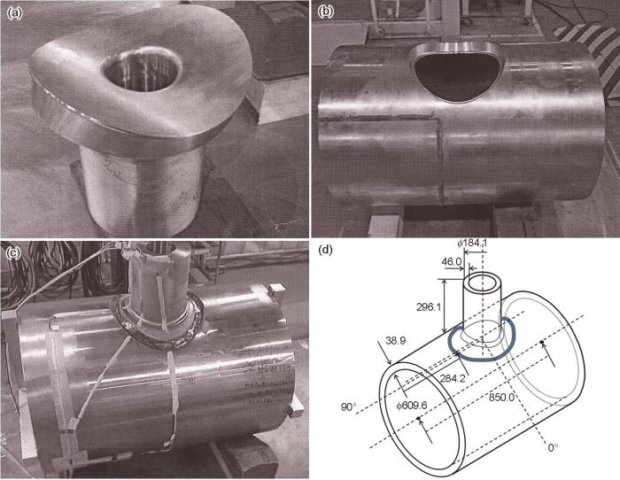
图1
SUS316台管、母管、管-管接头的照片及特征尺寸示意图
Fig.1
Photographs of a vice-tube (a), a circular pipe (b), and a saddle tube-pipe joint (c), the dimension diagram of the tube-pipe welded joint (unit: mm) (d)
表1 SUS316母材及Y316L焊材的化学成分 (mass fraction / %)
Table 1
| Material | C | Si | Mn | P | Ni | Cr | Mo | S | Fe |
|---|---|---|---|---|---|---|---|---|---|
| SUS316 | 0.08 | 1.00 | 2.00 | 0.045 | 12-14 | 16-18 | 2-3 | < 0.002 | Bal. |
| Y316L | 0.04 | 0.33 | 1.88 | < 0.019 | 12.70 | 19.30 | 2.26 | < 0.002 | Bal. |
图2

图2
焊道布置及热电偶位置示意图
Fig.2
Schematic of an arrangement of weld passes and locations of thermo-couples
表2 各焊道焊接速率、热输入及电弧效率
Table 2
| Layer number | Bead number | Welding speed / (mm·min-1) | Heat input / (kJ·cm-1) | Arc efficiency |
|---|---|---|---|---|
| 1 | 1 | 48.5 | 7.2 | 0.57 |
| 2, 3 | 2-5 | 103.4-127.6 | 7.1-12.1 | 0.7 |
| 4-11 | 6-28 | 151.5-192.6 | 15.7-16.7 | 0.7 |
| 12-14 | 29-40 | 216.1-216.6 | 13.5-13.7 | 0.7 |
| 15, 16 | 41-51 | 225.5-249.7 | 11.8-12.9 | 0.7 |
1.2 应力测量方法及位置
图3

图3
应变片位置俯视图及各截面应变片位置示意图
Fig.3
Schematics of strain gauge locations in top view (a), and strain gauge locations in 90° and 180° cross-section (b)
2 有限元计算方法
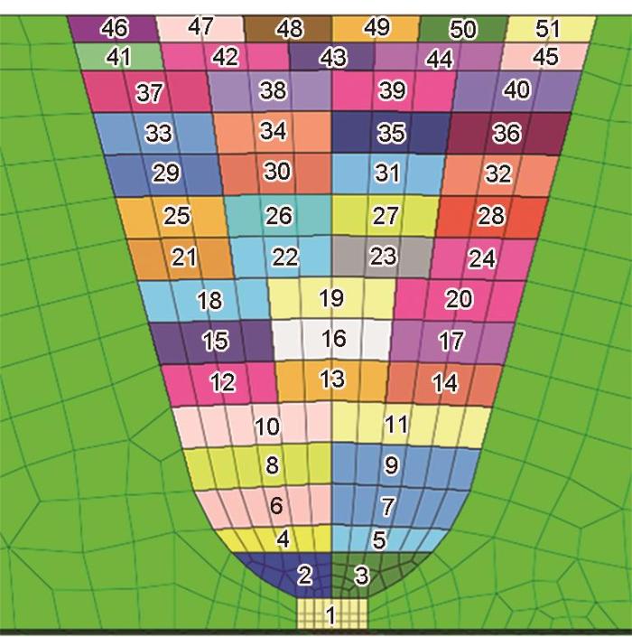
基于MSC. Marc软件平台,本工作建立了2种计算马鞍形管-管接头残余应力的有限元方法,为了方便后续讨论,这2种有限元计算模型分别用Model 1和Model 2表示。第1种方法(Model 1)建立了与实际焊接工件尺寸完全一致的三维有限元网格模型,如图4a所示。在模拟焊接热输入时,坡口下部打底焊道(第1条焊道)和紧接着的第2、3焊道及上部的第46~51盖面焊道采用移动热源模型,其余填充焊道均采用瞬间热源模型。第2种方法(Model 2)为了更进一步提高计算效率与节省计算储存空间,根据该接头几何形状的对称性简化为1/4局部模型,如图4b所示,并在对称面上设置绝热边界条件与对称位移拘束,所有焊道均采用瞬间热源进行温度场计算。Model 1与Model 2的焊道布置如图5所示。焊道采用“生死单元”的方式进行激活。采用移动热源模型时,当热源移动到当前材料位置时,对应的单元被依次激活;当采用瞬间热源时,当前焊道对应的所有单元同时被激活。
图4
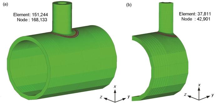
图4
全尺寸(Model 1)和1/4尺寸(Model 2)有限元网格模型
Fig.4
Schematic finite element models of full size model (Model 1) (a) and a quarter model (Model 2) (b)
图5
2.1 温度场计算
式中,Q = ηUI (其中,Q为电弧功率(W),η为电弧热效率,U为电弧电压(V),I为焊接电流(A));af、ar、b和c为椭球形状参数;ff和fr为前、后椭球热量分配系数,且ff + fr = 2,在本研究中,取ff = 0.6,fr = 1.4。
理论上而言,对于多层多道的焊接构件,所有焊道采用移动热源模型来模拟热输入可以获得更接近于实际情况的温度场、残余应力和变形。但是,本工作中的马鞍形管-管接头具有焊接道数多和焊道轨迹复杂的特点,如果全部采用移动热源需要消耗大量的计算资源和冗长的计算时间。为了解决上述矛盾,本研究在可变长度热源模型[17]的基础上,提出了“移动热源+瞬间热源”混合计算法,即采用移动热源模型来模拟打底焊道和盖面焊道的热输入,采用瞬间热源模型来模拟中间填充焊道的热输入。这样的处理方式,既可以大幅节省计算时间和存储空间,也可以兼顾计算精度。
式中,L为整条焊缝的长度(mm),v为移动热源焊接速率(mm/s),V为该整条焊道的体积(mm3)。
2.2 应力场计算
应力与变形计算采用热-弹-塑性有限元计算法,即计算各个节点温度场后,再将其以热载荷加载到结构分析有限元模型中,从而求解整个焊接过程的位移、应变和应力,本工作采用的SUS316材料高温热物理性能和高温力学性能参数见文献[10]。
金属材料在焊接过程中热-冶金-力学的耦合行为非常复杂,在焊接热循环作用下,理论上材料的应变包括弹性应变、塑性应变、热应变、相变应变(固态组织转变引起的应变)和蠕变应变等成分。由于本工作采用的母材和焊接填充材料均为奥氏体不锈钢,不需要考虑固态相变问题。此外,焊接过程中加热和冷却速率都较快,这样在高温停留的累积时间相对较短,所以蠕变应变的影响也可以忽略不计[21]。对于SUS316钢,材料的总应变增量(Δεtotal)可以表达为:
式中,Δεe为弹性应变增量,Δεth为热应变增量,Δεp为塑性应变增量。
材料模型中,假定弹性行为遵循各向同性Hook定律[22],塑性行为遵循Von Mises屈服准则[22]。以往的研究[23]表明,SUS316奥氏体不锈钢是一种加工硬化较显著的材料,若不考虑加工硬化效应,得到的残余应力将远低于实际水平;若采用各向同性硬化准则考虑不锈钢的加工硬化,但不考虑退火软化效应,焊接数值模拟得到的应力结果会高于实验结果。因此本工作中,同时采用各向同性加工硬化模型和“阶跃式”退火软化模型考虑SUS316不锈钢的加工硬化和退火软化计算焊接残余应力。各向同性硬化法则中,流变应力与塑性应变(εp)有关,在模拟残余应力时,本工作采用的SUS316奥氏体不锈钢不同温度与不同塑性应变对应的流变应力如表3[24]所示。采用“阶跃式”模型来考虑退火软化效应时,退火温度设置为900℃[25]。
表3 SUS316不锈钢各向同性硬化准则模型参数[24]
Table 3
| T / oC | σs | σ0.01 | σ0.05 | σ0.1 | σ0.3 |
|---|---|---|---|---|---|
| 920 | 216.5 | 295.6 | 398.9 | 441.8 | 500.5 |
| 275 | 158.0 | 223.6 | 320.9 | 363.0 | 422.1 |
| 550 | 131.5 | 188.2 | 280.7 | 321.3 | 378.9 |
| 750 | 105.9 | 147.9 | 207.0 | 226.4 | 248.9 |
| 900 | 93.1 | 103.7 | 107.0 | 107.5 | 107.5 |
| 1000 | 31.8 | 31.8 | 31.8 | 31.8 | 31.8 |
| 1100 | 19.7 | 19.7 | 19.7 | 19.7 | 19.7 |
| 1400 | 2.1 | 2.1 | 2.1 | 2.1 | 2.1 |
| 1500 | 2.1 | 2.1 | 2.1 | 2.1 | 2.1 |
3 结果与分析
3.1 焊接热循环
为了比较分别由数值模拟和实验手段获得的焊接热循环,选取母管上4个代表位置(图2中A、B、C和D点)来输出热循环曲线,这4个位置均在母管的90°截面上。A、B位置在第1道焊接过程中的温度循环曲线如图6a所示,C、D位置在第46道焊接过程中的温度循环如图6b所示。从图6可以看出,尽管计算值与实验值在局部有些许差异,但整体而言,不论是各点的峰值温度还是升温和降温过程都与实验结果比较吻合。从数值模拟结果与实测值的比较可知,不管是移动热源模型+瞬间热源模型的Model 1,还是采用纯瞬间热源的Model 2计算得到的温度循环与实验结果均吻合较好。因此,可以推测,采用瞬间热源也能较高精度预测焊接残余应力,而且能大幅节约计算时间。
图6

图6
焊接温度循环结果和实验结果的比较
Fig.6
Comparison between simulated and experimental results for the welding temperature as a function of time
(a) the 1st pass (the measurement locations at points A and B (inset))
(b) the 46th pass (the measurement locations at points C and D (inset))
3.2 焊接残余应力
为了与实验结果进行定量比较和便于分析残余应力的分布特征,对残余应力计算结果进行了坐标变换,即将直角坐标系(x, y, z)转换为圆柱坐标(r, θ, z1) (其中,r方向为径向方向(应力实验中横向应力方向),θ方向为周向方向(应力实验中纵向应力方向),z1方向为轴向方向(为径向与周向共同决定平面的法向方向))。坐标变换及柱坐标原点位置如图7所示。柱坐标转化后,沿着r方向的应力为径向残余应力,沿着θ方向的残余应力为周向残余应力,z1方向的残余应力为轴向残余应力。
图7

图7
残余应力结果坐标系变换(直角坐标转柱坐标)
Fig.7
Schematic showing the transformation from the coordinate to cylindrical coordinate for the residual stress (r—direction of transverse residual stress, θ—direction of longitudinal residual stress, z1—the axial direction)
3.2.1 周向残余应力
图8为Model 1与Model 2的整体周向残余应力(类似平板接头的纵向残余应力)分布云图。总体上而言,这2个模型计算得到的周向残余应力的分布形态十分相似。在Model 1 (图8a)的外表面焊缝始终端位置(0°)可以清晰地看到该处的应力分布与其他位置有较显著的差异。而在Model 2 (图8b)中,由于全部焊道采用瞬间热源模型及对称的热边界和力学边界条件,因此沿着焊缝周向方向的残余应力,不会像Model 1在0°处出现不连续现象,故而呈现出光滑的连续分布特征。图9为Model 1在0°、90°、180°和270°截面上焊缝及其附近区域的周向残余应力分布云图。从4个截面上应力分布云图可以看到,焊缝及其附近的周向残余应力都为拉应力,最后一道焊缝位置及其附近区域的残余应力最大,该处峰值应力达到甚至超过600 MPa。由于盖面焊道采用了移动热源,加之各个截面处的内拘束不同,4个截面上的应力分布也有所不同,不过分布形态基本相似,峰值应力的大小和所在位置也基本相同。
图8
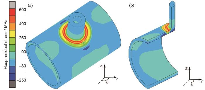
图8
焊接完成后Model 1与Model 2整体周向残余应力分布云图
Fig.8
Overall hoop residual stress distributions after welding for Model 1 (a) and Model 2 (b)
图9

图9
Model 1典型截面上的周向残余应力云图
Fig.9
Hoop residual stress distributions in the characteristic cross-sections for Model 1
(a) 0° (b) 90° (c) 180° (d) 270°
图10
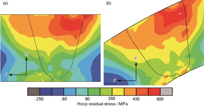
图10
Model 2典型截面上的周向残余应力云图
Fig.10
Hoop residual stress distributions in the characteristic cross-sections for Model 2
(a) 90° (b) 180°
图11为管-管接头在90°截面的上表面(line 1)和下表面(line 2)的周向残余应力分布,该图比较了数值模拟结果与实验测量结果。在line 1上的应力分布如图11a所示,在-20~0 mm范围内,2种模型的计算结果与实验测量结果吻合很好。在-10 mm附近,周向残余应力达到最大值,2种模型计算得到的最大值和实验测量得到的最大值分别为534、547和506 MPa。Model 1的计算结果在0~15 mm范围内低于实验值,平均低了约40 MPa。Model 2的计算结果在15~25 mm范围内高于实验测量结果,平均高了约50 MPa;应力分布形态与测量结果基本一致。总体上来看,在line 1上数值模拟结果得到的应力分布与实验值一致。line 2上的周向残余应力分布如图11b所示,从此图可知,整体上而言实验值与计算值具有较高的吻合度。
图11

图11
90°处上(line 1)下(line 2)表面周向残余应力实验值与计算值
Fig.11
Experimental and numerical results of the hoop residual stress in 90° cross-section, located at line 1 (a) and line 2 (b) (Insets show the measuring directions)
图12
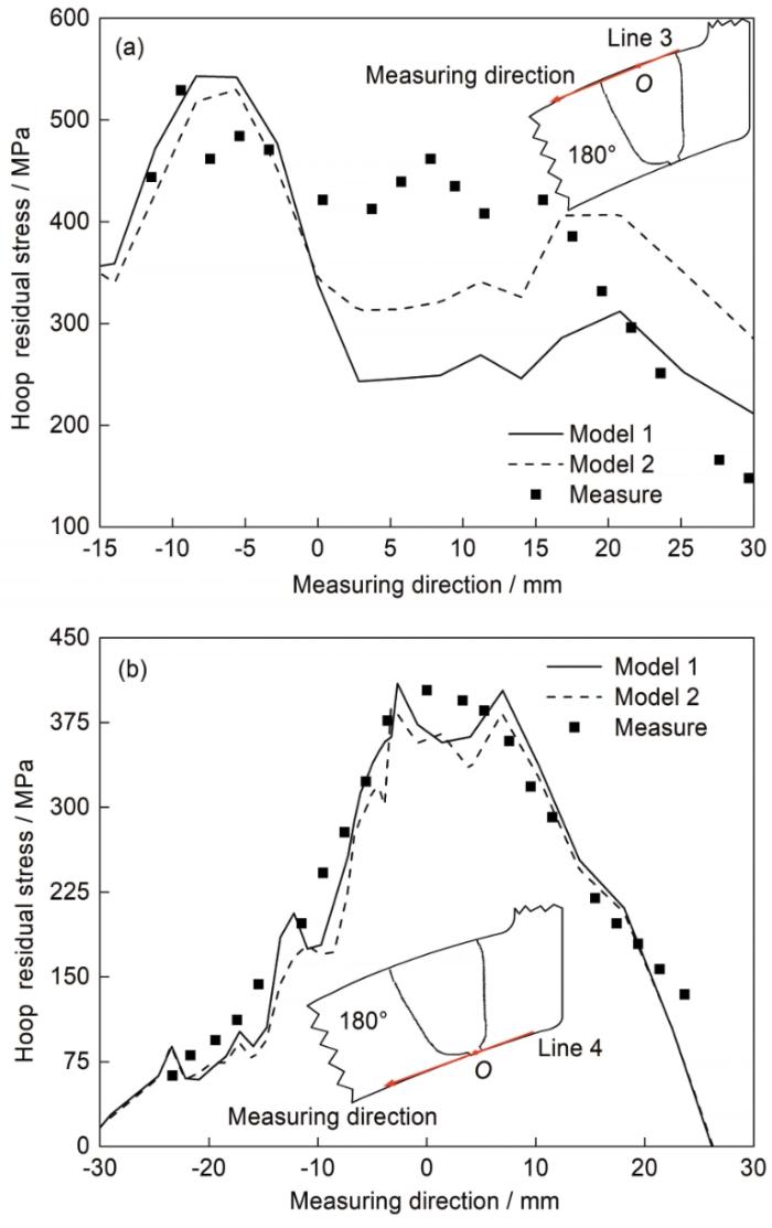
图12
180°处上(line 3)下(line 4)表面周向残余应力实验值与计算值
Fig.12
Experimental and numerical results of the hoop residual stress in 180° cross-section, located at line 3 (a) and line 4 (b) (Insets show the measuring directions)
图13为焊缝中心线line 5上周向残余应力的分布。图中5条曲线分别表示了第2、6、9、12和16层焊接完成时的周向残余应力分布。从此图可以看到一个有趣的周向应力的演化过程,即随着焊接进行,焊道的增加,沿着焊缝中线的周向应力的大小和分布在不断发生变化。也就是说,后焊焊道对先焊焊道产生的应力分布有显著的影响。对于下表面焊缝中心位置的周向应力而言,随着焊道数增加,其值有不断减小的趋势。产生这种变化趋势主要是因为接头本身板厚较厚,加之焊道数和焊接层数较多,周向应力分布除了在与焊缝中线垂直方向(横向方向)上产生平衡外,在厚度方向也产生平衡。
图13

图13
周向残余应力沿中心线分布(90°截面上不同焊层完成后)
Fig.13
Hoop residual stress distributions along the welding centerline in 90° section after welding at different layers (Inset shows the measuring direction)
3.2.2 径向残余应力结果
图14a和b分别为Model 1与Model 2整体径向残余应力(类似平板接头的横向残余应力)分布云图。整体上而言,Model 1与Model 2残余应力分布形态非常相似,但在Model 1的外表面焊缝始终端位置(0°)可以清晰地看到径向残余应力分布与周向残余应力呈现相似的不光滑的局部区域。而Model 2中,由于全部焊道采用瞬间热源模型及对称的热边界和力学边界条件,故径向方向的残余应力呈现出光滑连续的分布特征。
图14

图14
焊后Model 1与Model 2整体径向残余应力分布云图
Fig.14
Overall radial residual stress distributions for Model 1 (a) and Model 2 (b)
图15为Model 1在0°、90°、180°和270°截面上焊缝及其附近区域的径向应力分布云图。径向残余应力在焊缝上表面为拉应力,且呈现出离焊缝越近拉应力越高的特征。根据Dong[26]的研究,管-管对接环焊缝在轴向方向(与子母线平行的方向)应力(在本工作中为径向应力)的分布,可分为弯曲型(bending-type)和自平衡型(equilibrating-type) 2种类型。本工作虽然是马鞍型接头,但它也有类似于环焊缝的一些特征,其沿厚度方向上的径向残余应力呈现拉-压-拉的分布特征,类似于厚大尺寸环焊缝自平衡类型[10]。对0°、90°、180°和270°不同截面位置的径向应力分布比较可知,90°与270°截面的径向残余应力大小与分布均非常相似,同时0°与180°截面的径向残余应力大小与分布也非常相似;而90°与180°截面位置径向残余应力有显著的差异。因此可以推测,对于该马鞍形管-管接头而言,采用从90°至180°截面区域的1/4模型即可描述整体结构的径向残余应力分布。
图15

图15
Model 1典型截面上的径向残余应力云图
Fig.15
Radial residual stress distributions in the characteristic cross-sections for Model 1
(a) 0° (b) 90° (c) 180° (d) 270°
图16
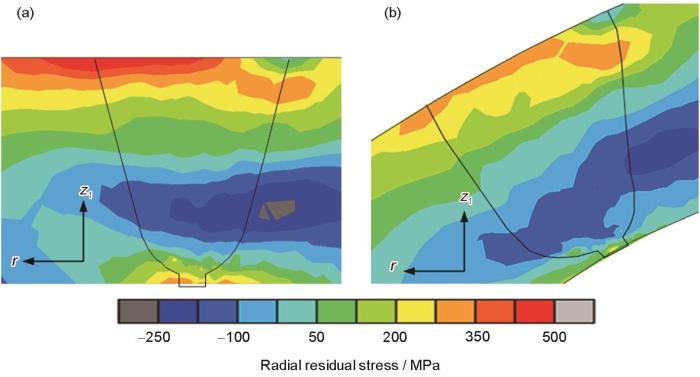
图16
Model 2典型截面上的径向残余应力云图
Fig.16
Radial residual stress distributions in 90° (a) and 180° (b) cross-sections for Model 2
图17为90°截面的上表面(line 1)和下表面(line 2)上径向残余应力分布。图17a为line 1上的径向残余应力分布,整体上看2者的分布形态基本一致,2者的峰值拉伸应力位置也很接近。实验测量的最大值为448 MPa,相同位置Model 1的值为451 MPa,Model 2的值为484 MPa;在-20 mm处实验测量的最小值为128 MPa,相同位置上Model 1与Model 2的值分别为41和25 MPa。在90°截面位置的下表面line 2上的径向残余应力分布如图17b所示,可以看到,无论是应力分布形态还是大小,数值模拟结果与实验结果吻合良好。整体上而言,实验值略高于计算值。在line 2上,实验测量最大值为393 MPa,而Model 1与Model 2对应的计算值分别为367和348 MPa,实验与计算得到的残余应力峰值和分布吻合较好。
图17
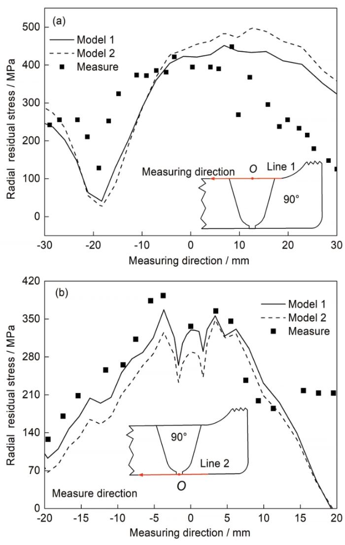
图17
90°处上(line 1)下(line 2)表面径向残余应力实验值与计算值
Fig.17
Experimental and numerical results of radial residual stress in 90° cross-section, located at line 1 (a) and line 2 (b) (Insets show the measuring directions)
图18

图18
180°处上(line 3)下(line 4)表面径向残余应力实验值与计算值
Fig.18
Experimental and numerical results of radial residual stress in 180° cross-section, located at line 3 (a) and line 4 (b) (Insets show the measuring directions)
图19为焊缝中心线line 5上径向残余应力的分布。图中5条曲线分别表示了第2、6、9、12和16层焊接完成时的径向残余应力分布。随着焊接进行,焊层数的增加,沿着焊缝中线的径向应力的大小和分布不断发生变化,这说明后焊焊道对先焊焊道产生的径向应力分布有显著的影响。随着焊道数的增加,下表面焊缝中心位置的径向应力呈现出先减小随后又增加的趋势,沿着焊缝中线的径向应力在焊接过程中的演化过程与周向应力的演化过程有明显的不同,前者先减小后增大,而后者随着焊道增加又有一直减小的趋势。出现这种现象是因为径向应力分布除了在与焊缝中线垂直方向(横向方向)上产生平衡外,在厚度方向也产生平衡。
图19
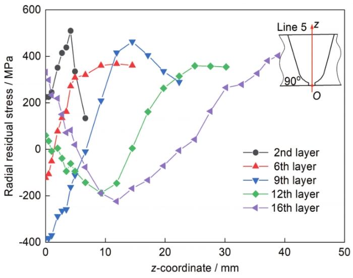
图19
径向残余应力沿中心线分布(90°截面上不同焊层完成后)
Fig.19
Radial residual stress distributions along the welding centerline in 90° section after welding different layers (Inset shows the measuring direction)
3.3 计算时间与储存空间
下面对2种方法的计算效率进行定量比较。2个模型的计算均在i9-9900K (CPU参数为8核16线程,主频为4.7 GHz) 的计算机上完成,采用移动热源模型计算第1道焊的应力时所花费的时间为9.65 h,第2道焊的时间花费9.68 h,第3道焊用时为9.69 h。从数值上看,3个焊道计算时间的差异较小,平均每个焊道的计算时间为9.67 h。根据前3道的所用计算时间可以得到这样一个推测,全模型+全移动热源模型,51道全部采用移动热源模型来计算焊接应力,所需计算时间约为493 h。当采用Model 1来计算焊接应力时,实际花费时间为137 h,而采用Model 2,计算时间仅仅为8.4 h。单纯从计算时间上看,采用全模型及全焊道移动热源模型花费的时间最长;采用Model 1的计算时间居中,所用时间仅为前者的27.7%;而采用Model 2的计算时间最少,以全模型+全移动热源模型为参照,所用的计算时间仅为它的1.9%。
从所需的存储空间而言,Model 1与Model 2所需的储存空间分别为1604和191 GB。比较而言,采取Model 2可大大节约储存空间。基于计算时间和储存空间的比较,Model 2具备更强的工程应用潜力。
3.4 讨论
本工作采用Model 1和Model 2计算了厚大马鞍形管-管焊接接头的温度场和残余应力,并与实验结果进行了比较。不论是典型位置的焊接热循环还是焊缝及其附件区域的残余应力,数值模拟结果与实验测量值总体上吻合良好。
3.4.1 计算误差
数值模拟得到的残余应力与实验测量结果尽管在峰值应力和分布形态上基本一致,但依然存在一定程度的差异。通过分析,主要的原因如下:
(1) 初始材料状态难考虑。在实际制备母管和台管时,材料经过固溶处理、矫正变形及机械加工等焊前的工序,这些工序可能会产生不同程度的塑性变形以及初期残余应力,在有限元模型中这些焊前材料初始状态没有被考虑,从而产生误差。
(2) 实验测量残余应力带来的误差。实验测量采用应力释放法进行残余应力测量时,需要在测量位置进行应变片的粘贴。在应变片粘贴前,需要将测量位置打磨平整,由于在180°截面的位置存在一定弧度,故而需要在基体上打磨掉的材料较多,才能达到平整的效果。在这个过程中,打磨较多会对焊缝位置引入额外的塑性应变,使测量结果出现误差。从位置看,在180°处因打磨造成的误差可能会更大。
(3) 有限元计算模型误差。在材料模型中,本工作采用“各向同性硬化模型”和“阶跃式退火模型”来分别考虑加工硬化和退火软化效应,而实际的材料会出现包辛格(Bauschinger)效应,同时软化效应与时间和温度都有密切关系。在本工作采用的材料模型中,上述的问题没有完整地考虑,在今后的研究中,需要开发更高精度的材料模型。
3.4.2 应力峰值
实验测量结果和计算结果均显示,在焊接后接头中存在大于550 MPa的高拉应力区,而SUS316不锈钢的常温屈服强度仅为220 MPa,应力峰值远远超过了材料的常温屈服强度。出现如此高的拉伸残余应力的主要原因如下:
(1) SUS316奥氏体不锈钢的加工硬化效应显著。在焊接过程中,焊缝金属及其附近的母材都要经历峰值温度较高的热循环,由于焊缝及其附近的材料在升温和降温过程中产生的热应变要受到周围温度相对较低金属的拘束作用而发生塑性变形,塑性变形的产生致使材料发生加工硬化而提高流变应力。
(2) 由于本工作中的焊接接头板厚较厚,而且形状相对复杂,因此焊缝处的三向内拘束较大。在内拘束大的情况下,焊接过程中容易产生多轴(二轴或三轴)拉伸应力,这样会导致材料不易屈服。
式中,σs为屈服强度。
图20

图20
SUS316不锈钢空间Von Mises屈服面与平面Von Mises屈服面及其扩大示意图
Fig.20
Schematics of SUS316 Von Mises yield surface in the triaxial stress state (a) and the Von Mises yield surface expansion in the biaxial stress state (b) (σ1—major principal stress, σ2—second principal stress, σ3—third principal stress, σs—yield strength, σ
若只考虑2个应力,可假设σ3 = 0时,
图21

图21
Model 1模型90°截面等效Von Mises应力
Fig.21
Equivalent Von Mises stress distributions in 90° cross-section for Model 1
采用的加工硬化及退火软化模型计算得到残余应力,与实验得出的残余应力接近,验证了材料模型准确性。从计算结果和实验结果来看,由于对模型热源的简化和对材料模型的近似处理,使该模型占用的计算资源较少,同时计算时间也大幅缩短。基于应力分布形态及峰值应力实验结果有较高吻合度的事实,从面向工程应用的角度出发,本工作开发的2种计算手法具有较高的工程应用价值。
4 结论
(1) 基于通用有限元软件,针对结构较大、焊道布置复杂的SUS316马鞍形管-管接头温度场和残余应力的计算,开发了全尺寸有限元网格模型+“移动热源+瞬间热源”混合计算模型(Model 1)以及1/4部分网格有限元模型+全焊道瞬间热源模型(Model 2)。计算结果与实验结果吻合较好,验证了2种模型的可行性和妥当性。
(2) Model 1能计算出整体结构焊接时的残余应力,并且也能抓住始终端位置的应力分布特征;Model 2虽然不能模拟始终端位置的应力,但可以较准确地获得除始终端位置及其附近以外区域的残余应力,而且计算时间可大幅缩短,存储空间也能大幅减少。在实际的工程应用中,对于厚大焊接接头或结构的焊接残余应力,若不重点考虑始终端位置的应力特征,可以利用结构的对称性简化模型,同时采用瞬间热源模型来模拟焊接热输入,这种方法可以兼顾计算精度并能大幅提高计算效率。
(3) 从数值模拟结果和实验测量结果来看,焊缝及其附近的残余应力呈现出多轴拉伸的特征,局部位置的单向(周向)应力达到了600 MPa,远远高于材料常温时的屈服极限。产生如此高的残余应力的原因主要有两点,一是SUS316材料有较显著的加工硬化倾向,另一个是在厚大接头焊接时内拘束强,而引起的多轴应力效应。
参考文献
Microstructure and local properties of a domestic safe-end dissimilar metal weld joint by using hot-wire GTAW
[J].
国产核电安全端异种金属焊接件的微观结构及局部性能研究
[J].
Effect of heat input on the microstructure, residual stresses and corrosion resistance of 304L austenitic stainless steel weldments
[J].
Investigations on welding residual stresses in penetration nozzles by means of 3D thermal elastic plastic FEM and experiment
[J].
Prediction of welding distortion in a curved plate structure by means of elastic finite element method
[J]. J.
Effects of constraints on residual stress of austenitic stainless steel welded joint
[J].
约束条件对奥氏体不锈钢对接接头残余应力的影响
[J].
Analysis of thermal elastic-plastic stress and strain during welding by finite element method
[J].
Investigation of numerical Modelling of TIG welding of austenitic stainless steel (304L)
[J].
Influence of multi-thermal cycle and constraint condition on residual stress in P92 steel weldment
[J].
多重热循环和约束条件对P92钢焊接残余应力的影响
[J].
Validated prediction of weld residual stresses in austenitic steel pipe girth welds before and after thermal ageing, part 2: Modelling and validation
[J].
Influence of size factor on calculation accuracy of welding residual stress of stainless steel pipe by 2D axisymmetric model
[J].
尺寸因素对2D轴对称模型计算不锈钢管焊接残余应力精度的影响
[J].
采用数值模拟和实验相结合的方法研究了尺寸因素对2D轴对称模型计算SUS316不锈钢管焊接残余应力精度的影响。基于通用有限元软件MSC. Marc,分别采用2D轴对称模型和3D模型计算了不同尺寸圆管对接接头的温度场和焊接残余应力分布,并将小尺寸管残余应力计算结果与实验测量结果进行了比较。结果表明,2D轴对称模型与3D模型计算结果整体吻合较好,但在靠近内表面的焊缝及近焊缝区域,焊接残余应力的幅值和拉压应力区域的大小存在一定差别,且差别随圆管尺寸的增加而增大。对于实际的工程应用,在不考虑始终端应力问题时,可以用2D轴对称模型代替3D模型计算环焊缝稳定区残余应力,从而节省大量计算时间。
Simulating welding residual stress and deformation in a multi-pass butt-welded joint considering balance between computing time and prediction accuracy
[J].
Influence of lumped-pass method on calculation accuracy and efficiency of welding residual stress in SUS304 stainless steel butt joints
[J].Thick-plate stainless steel welded joints are widely used in nuclear power plants and chemical factories, and the welding residual stresses of these joints have always been a focus of attention. The finite element method has been recognized as an effective way to calculate welding residual stress. Because the welding process is a highly nonlinear problem, the computational efficiency cannot meet the requirements under the existing computing hardware conditions. Based on the ABAQUS commercial software, an efficient instantaneous heat source model is developed to simulate welding residual stress of a multi-pass butt-welded joint with 25 mm thickness. Meanwhile, the simulated results of welding residual stress distribution is compared with that obtained by the traditional moving heat source model. In order to further improve the calculation efficiency, different lumped-pass patterns are designed to shorten the computing time. Experiments are also carried out to measure the residual stress distribution of the butt-welded joint. The comparison between the numerical results and the measured data shows that both the moving heat source model and the instantaneous heat source model can accurately predict welding residual stress, and the computing time of the latter is much shorter than that of the former. In addition, the influence of lumped-pass method on the residual stress of a multi-pass butt-welded joints with 75 mm thickness is investigated numerically. The numerical simulation results show that different lumped-pass patterns have a little effect on the longitudinal residual stress, but have a significant influence on the transverse residual stress. The calculation efficiency can be greatly improved by adopting instantaneous heat source and lumped-pass method, and this combined method will be an effective approach to solve the problem of residual stress calculation for thick-plate welded joints.
合并焊道法对SUS304不锈钢平板对接接头焊接残余应力计算精度和效率的影响
[J].
Influence of welding procedure on the residual stress of the welded thick-wall nuclear pressure vessel
[J].
焊接工艺对厚壁核压力容器焊接残余应力的影响
[J].
Study on weld residual stress and crack propagation evaluations for a saddle-shaped weld joint
[A].
Residual stress measurements
[A].
A new finite element model for welding heat sources
[J].
Numerical simulation of welding residual stresses in a multi-pass butt-welded joint of austenitic stainless steel using variable length heat source
[J].<p>Recent discoveries of stress corrosion cracking at welded joints in pressurized water reactors and boiling water reactors have raised wide concerns about the safety and integrity of plant components. It has been recognized that residual stress and applied stress on their surfaces largely increase the expanding risk of initial stress corrosion cracking. Therefore, it is very important to investigate the welding residual stress in welded joints. It is very expensive and time–consuming to measure the residual stress, and sometime is impossible. As an alternative approach a computational procedure on the basis of finite element method is effective in solving non–linear problems such as thermal and mechanical nonlinearity in a welding process. Accurately simulating welding residual stress not only needs generally a long computational time, but also strongly depends on the analyst’s experience and know–how which is a main hindrane for the welding process simulation. Therefore, it is an urgent task to develop a time–effective numerical simulation procedure to calculate welding temperature field and residual stress distribution. In this study, a new method on the basis of the vaiable length heat souce was developed to simulate the welding residual stress in a multi–pass butt–welded joint of austenitic stainless steel. Meanwhile, the experiment was carried out to obtain the welding residual stress in the utt–welded joint. Comparing the simulated with experimental results, it was found that this method could not only save a large amount of computational time but also provide a highly accurate numerical result for the residual stress in multi–pass butt–welded joints.</p>
用可变长度热源模拟奥氏体不锈钢多层焊对接接头的焊接残余应力
[J].采用可变长度热源模型对奥氏体不锈钢平板多层焊对接接头的残余应力进行了数值模拟, 同时也用实验方法测量了平板对接接 头上下表面的残余应力. 通过比较由热弹塑性有限元计算得到的残余应力与由电阻应变片法测量得到的实验结果得知, 采用该模型对多层焊对接接头残余应力的数值模拟, 不仅可以大大缩短计算时间, 也可以得到较高的计算精度.
Applicable conditions of instantaneous source used for welding heat conduction
[J].
Numerical simulation of welding residual stress in multi-pass T-joint of thick Q390 high strength steel plate using instantaneous heat source
[J].
用瞬间热源模拟Q390高强钢厚板多层多道焊T形接头的焊接残余应力
[J].
Influences of heat source model on welding residual stress and distortion in a multi-pass J-groove joint
[J].
Effects of yield strength of weld metal and material strain hardening on prediction accuracy of welding residual stress and deformation in a Q345 steel joint
[J].Establishing a suitable material model is the key to accurately predict welding residual stress and deformation by finite element method. Based on ABAQUS code, a thermal-mechanical finite element method is developed to predict the welding residual stress and deformation of the Q345 steel butt joint. Effects of the yield strength of weld metal and material strain hardening on the welding residual stress and deformation are analyzed by means of numerical simulation. Compared with the simulation results of ideal elastic-plastic model, the material model considering the yield strength of the base metal and the weld metal significantly increases the longitudinal residual stress of the weld zone and its vicinity. The material model considering the strain hardening and annealing softening effect obviously increases the longitudinal and transverse residual stresses in the lower surface of the weld joint. The material model considering the yield strength of weld metal, and the material model considering material strain hardening have slight effect on the angular distortion of the butt joint. Comparison between numerical simulation results and experimental results, in order to accurately predict the welding residual stress and deformation of Q345 steel multi-pass welded joints, the yield strength of the base metal and weld metal should be separately considered, as well as the strain hardening and annealing softening effect. The material model proposed lays a theoretical foundation for accurately predicting welding residual stress and deformation in Q345 high-strength low alloy steel joints or structures by finite element method.
焊缝金属的屈服强度和材料的加工硬化对Q345钢焊接残余应力与变形计算精度的影响
[J].建立合适的材料模型是有限元法准确预测焊接残余应力与变形的关键。基于有限元软件ABAQUS,采用热-弹-塑性有限元方法模拟Q345低合金高强钢平板对接接头的焊接残余应力与变形,探讨焊缝金属的屈服强度和材料的加工硬化对焊接残余应力和变形的影响。数值模拟结果表明,与理想弹塑性模型预测的结果相比,材料模型区分考虑母材和焊缝金属的屈服强度会明显增加焊缝及其附近区域的纵向残余应力,材料模型考虑材料的加工硬化及退火软化效应会显著增加焊接接头下表面的纵向和横向残余应力,材料模型考虑焊缝金属的屈服强度和材料的加工硬化及退火软化效应对平板对接接头角变形的影响较小。比较计算结果与试验结果可知,为准确地预测Q345钢接头焊接残余应力与变形,材料模型要区分考虑母材与焊缝金属的屈服强度、材料的加工硬化及退火软化效应。提出的材料模型为采用数值模拟方法高精度地获得Q345低合金高强钢接头或结构的残余应力与变形奠定了理论基础。
Comparison of welding residual stress and deformation induced by local vacuum electron beam welding and metal active gas arc welding in a stainless steel thick-plate joint
[J].
Influence of annealing temperature on calculation accuracy of welding residual stress in a SUS304 stainless steel joint
[J].Austenite stainless steels such as SUS304, owing to their good combination of mechanical properties, corrosion resistance and weldability, are widely used in a variety of industries. In the simulation of welding residual stress of an austenite stainless steel joint, because of the high strain hardening rate and the heating-cooling thermal cycles, both the work hardening phenomenon and the annealing effect have to be taken into account in the material constitutive relations. Though a number of numerical models have included the work hardening by using isotropic rule, kinematic rule or mixed rule, limited models have dealt with the annealing effect. For the steels or alloys with high strain hardening coefficient, neglecting the annealing effect will overestimate the welding residual stresses to a large extent. In this study, the thermal elastic plastic finite element method (T-E-P FEM) was used to simulate welding temperature and residual stresses in a SUS304 steel bead-on joint. In the computational approach based on the T-E-P FEM, a moving heat source with uniform density distribution was used to model the heat input, and a simple model was proposed to consider the annealing effect. Using the developed computational approach, the influences of work hardening and annealing effect on the welding residual stress were clarified. In addition, the effect of annealing temperature on the distribution and magnitude of welding residual stress in the weld zone and its vicinity was examined. The simulated results show that annealing effect has a significant influence on the longitudinal residual stress, and the peak value of longitudinal tensile stress increases with annealing temperature. The longitudinal tensile stresses in the fusion zone and its vicinity also increase with annealing temperature. It seems that the annealing temperature has insignificant influence on the transverse residual stresses. Comparing the simulated results and the measured data, it was found that when the annealing temperature was assumed to be 1000 ℃ for SUS304 steel, the longitudinal residual stresses predicted by the T-E-P FEM generally match the measurements. The present work is helpful for developing more advanced materials model to calculate welding residual stress with high accuracy.
退火温度对SUS304不锈钢焊接残余应力计算精度的影响
[J].采用热-弹-塑性有限元计算方法模拟了奥氏体不锈钢SUS304在单道堆焊时的温度场和应力场, 探讨了加工硬化和退火软化对焊接残余应力计算结果的影响, 重点考察了数值模型中的退火温度设定值对焊接残余应力计算精度的影响. 数值模拟结果表明: 退火软化效应对纵向残余应力的计算结果有明显影响, 随着退火温度设定值的升高, 纵向残余应力的峰值增大, 而且焊缝及其附近的纵向应力有整体升高的趋势.退火温度对横向残余应力的影响较小.比较计算结果与实验结果可知, SUS304钢的退火温度设定为1000 ℃时, 数值模拟结果与实测结果比较吻合.
The effect of plasticity theory on predicted residual stress fields in numerical weld analyses
[J].
Influence of strain hardening and annealing effect on the prediction of welding residual stresses in a thick-wall 316 stainless steel butt-welded pipe joint
[J].Stress corrosion cracking (SCC) is a major problem in the welded components of austenitic stainless steel in nuclear power plants. High tensile residual stress is an important factor resulting in the SCC of materials. Austenitic stainless steel has a strong tendency for work hardening owing to its fcc crystal structure and low stacking-fault energy. High plastic strain can accumulate during a multipass welding process. On the other hand, accumulated strain hardening can be reduced or even eliminated during the welding thermal cycles owing to dynamic recovery, recrystallization, and grain growth below the melting point, which is called the annealing effect. Influence of strain hardening and annealing effect needs to be investigated to predict the welding-induced residual stresses accurately in austenitic stainless steel joints. In this study, a new time-temperature-dependent annealing model was proposed based on the Johnson-Mehl-Avrami equation. Numerical Satoh tests were performed to clarify the influence of strain-hardening models (i.e., the isotropic strain-hardening model and Chaboche mixed isotropic-kinematic strain-hardening model) and annealing models (i.e., the single-stage annealing model and new time-temperature-dependent annealing model) on the formation of residual stresses and the accumulated plastic strain during multiple thermal cycles. Thermoelastic-plastic finite element (FE) analyses were carried out to predict the welding residual stresses and accumulated plastic strain in a thick-wall 316 stainless steel butt-welded pipe joint with 85 welding passes. The residual stresses of the welded joint were measured by the sectioning method, inherent strain method, and deep-hole drilling method. The simulations of welding residual stresses were compared with the measurements. Annealing effect significantly influences the formation of accumulated plastic strain and welding residual stresses, neglecting which will result in a significant overestimation of FE results. The proposed annealing model showed an excellent match to the experimental data. With the consideration of the annealing effect, the isotropic strain-hardening model overestimated the welding residual stresses slightly, while the FE results of welding residual stresses using the Chaboche mixed strain-hardening model showed better agreement with the measurements. The single-stage annealing model revealed a recommended annealing temperature of 900-1000°C for austenitic stainless steel such as 316 stainless steel.
加工硬化和退火软化效应对316不锈钢厚壁管-管对接接头残余应力计算精度的影响
[J].
On the mechanics of residual stresses in girth welds
[J].
