Corresponding authors:LIU Riping, professor, Tel:(0335)8074723, E-mail:riping@ysu.edu.cnMA Mingzhen, professor, Tel:(0335)8074723, E-mail:mz550509@ysu.edu.cn
Bulk amorphous alloys possess a metastable structure, which is difficult to process and manufacture into components or parts by conventional forging or welding. Instead, components or parts from bulk amorphous alloys can be fabricated by vacuum casting with the fluidity of bulk amorphous-alloy melts. Based on the casting forming of bulk amorphous alloys, this paper briefly introduces the fluidity and filling ability of bulk amorphous-alloy melts. In addition, the technical methods and applications of vacuum die casting, vacuum suction casting, gravity casting in a water-cooled copper crucible, and phase-change refrigeration casting are also mentioned. The theoretical problems and technical bottlenecks to be resolved in the forming process of bulk amorphous alloys are then discussed. Finally, the engineering application prospects of bulk amorphous alloys are suggested.
LIU Riping, MA Mingzhen, ZHANG Xinyu. New Development of Research on Casting of Bulk Amorphous Alloys. Acta Metallurgica Sinica[J], 2021, 57(4): 515-528 DOI:10.11900/0412.1961.2020.00414
Fig.1
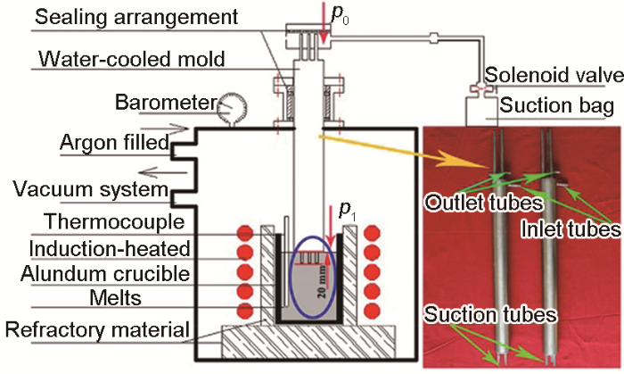
Schematic of fluidity test apparatus and photograph of water-cooled mold[38] (p0—pressure in the suction tube, p1—pressure on the liquid surface)
Fig.2
Influence of casting temperatures and pressures on fluidity length at radii of 2.0 mm (a), 2.5 mm (b), and 3.0 mm (c); influence of casting pressures and radii on fluidity length at 1123 K (d); and longitudinal section of fluidity sample of 6 mm diameter under different casting conditions (e) (I: 1273 K, 0.025 MPa; II: 1173 K, 0.025 MPa; III: 1123 K, 0.020 MPa. Δp—pressure difference between two ends of circular pipe, r—radius of circular tube)[38]
Table 1 Quality of fluidity test sample of 6 mm in diameter[38]
Temperature / K
Δp / MPa
0.020
0.025
0.030
0.035
1073
●
●
◘
◘
1123
●
◘
◘
◘
1173
◘
◘
◘
◘
1223
◘
☆
☆
☆
1273
◘
☆
☆
☆
Note: Symbol ● represents filling integrity; ◘ represents a small amount of gas holes or misrun; and ☆ represents a considerable number of casting defects
Fig.3
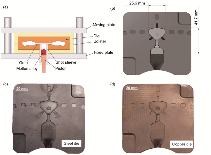
Schematic illustration of the high pressure die casting setup (a), 3D model of the die (b), and completed dies made from heat resistant steel and a copper alloy (c, d)[40]
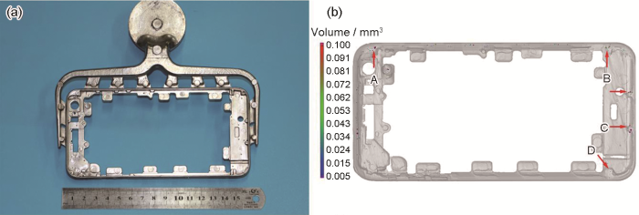
Fig.6
Image of Zr55Cu30Ni5Al10 bulk metallic glasses (BMGs) smartphone frame and the corresponding runner system (a), and the 3D distribution of the porosity in the smartphone frame (b) (A, B, C, and D denote different regions)[41]
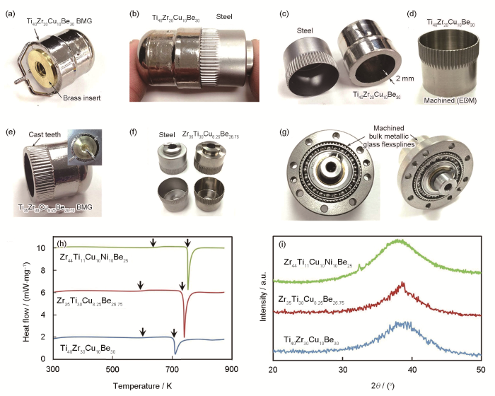
(a) suction casting over brass inserts was used to create a cup from a Ti-based BMG
(b) comparing the outer shape of the BMG cup to a machined steel flexspline
(c) the minimum thickness of the cup using suction pressure was 2 mm. The wall was thinned via conventional machining
(d) electrial discharge machining (EDM) was used to machine the teeth in the flexspline resulting in the final shape
(e) attempts were made to cast the teeth of the flexspline using and EDMed mold (inset)
(f) comparison of fully prototyped BMG flexspline with a steel version
(g) an assembled, functioning strain wave gear (SWG) utilizing a BMG flexspline from Fig.8f
(h) DSC traces of three BMG alloys cast into flexsplines. The lower two plots were prototyped using lab-grade material while the other plot is from a commercially cast part
(i) XRD spectra of three BMG alloys cast into flexsplines, showing mostly amorphous microstructure even in fairly large parts
Fig.8
Prototyping bulk metallic glass flexsplines, and DSC curves and XRD spectra[46]
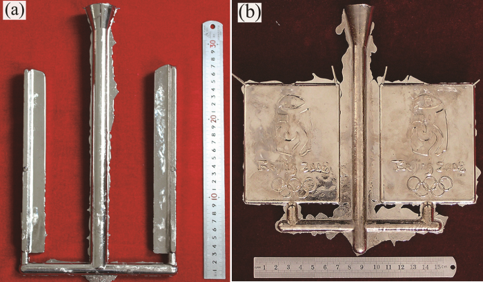
(a, b) 50 mm and 20 mm diameter BMG flexsplines cast to near net shape from the alloy LM1b. After casting, the samples have been de-gated and holes machined into the bottom (c, d) inserting the BMG flexspline into a commercial steel outer spline (e) a fully assembled hybrid CSG-20 SWG with a BMG flexspline (f) a still from a video of the BMG flexspline being driven by the wave generator after submersion in liquid nitrogen (g, h) testing a fully assembled SWG with a BMG flexspline at liquid nitrogen temperatures (i) example of different BMG alloys cast into flexsplines. In total, four alloys were fabricated commercially, as shown (j) optimal micrographs from the larger 50 mm diameter flexspline comparing the steel part to the cast BMG part (k) images of 20 mm diameter flexsplines from machined steel, machined BMG and two cast BMG (l) a schematic showing approximate cost associated with machining steel flexsplines and casting > 1.0 × 10⁴ BMG flexsplines. BMGs can be cast down to ~20 mm in diameter before thermoplastic forming techniques must be used to achieve micro-sized flexsplines. Multi-part casting is possible at small flexspline dimensions
Recent development and application products of bulk glassy alloys
[J]. Acta Mater., 2011, 59: 2243
TianH F, QiaoJ W, YangH J, et al.
The corrosion behavior of in-situ Zr-based metallic glass matrix composites in different corrosive media
[J]. Appl. Surf. Sci., 2016, 363: 37
LiB, SunW C, QiH N, et al.
Effects of Ag substitution for Fe on glass-forming ability, crystallization kinetics, and mechanical properties of Ni-free Zr-Cu-Al-Fe bulk metallic glasses
[J]. J. Alloys Compd., 2020, 827: 154385
JinZ S, YangY J, ZhangZ P, et al.
Effect of Hf substitution Cu on glass-forming ability, mechanical properties and corrosion resistance of Ni-free Zr-Ti-Cu-Al bulk metallic glasses
Strong work-hardening behavior induced by the solid solution strengthening of dendrites in TiZr-based bulk metallic glass matrix composites
[J]. J. Alloys Compd., 2015, 624: 9
HilkeS, RösnerH, GeisslerD, et al.
The influence of deformation on the medium-range order of a Zr-based bulk metallic glass characterized by variable resolution fluctuation electron microscopy
[J]. Acta Mater., 2019, 171: 275
FuJ, ZhuY H, ZhengC, et al.
Effect of laser shock peening on the compressive deformation and plastic behavior of Zr-based bulk metallic glass
[J]. Opt. Lasers Eng., 2016, 86: 53
MaD Q, LiJ, ZhangY F, et al.
Effect of compositional tailoring on the glass-forming ability and mechanical properties of TiZr-based bulk metallic glass matrix composites
Manufacture of die casting equipment for Zr based bulk metallic glass and its industrialization progress
[A]. Special Issue of 2016 Annual Meeting of Special Casting & Nonferrous Alloy [C]. Nantong: Chinese Society of Mechanical Engineering, Chinese Society of Ordnance Engineering, 2016: 254
Recent development and application products of bulk glassy alloys
0
2011
The corrosion behavior of in-situ Zr-based metallic glass matrix composites in different corrosive media
0
2016
Effects of Ag substitution for Fe on glass-forming ability, crystallization kinetics, and mechanical properties of Ni-free Zr-Cu-Al-Fe bulk metallic glasses
0
2020
Effect of Hf substitution Cu on glass-forming ability, mechanical properties and corrosion resistance of Ni-free Zr-Ti-Cu-Al bulk metallic glasses
Strong work-hardening behavior induced by the solid solution strengthening of dendrites in TiZr-based bulk metallic glass matrix composites
0
2015
The influence of deformation on the medium-range order of a Zr-based bulk metallic glass characterized by variable resolution fluctuation electron microscopy
0
2019
Effect of laser shock peening on the compressive deformation and plastic behavior of Zr-based bulk metallic glass
0
2016
Effect of compositional tailoring on the glass-forming ability and mechanical properties of TiZr-based bulk metallic glass matrix composites
... [38]Schematic of fluidity test apparatus and photograph of water-cooled mold<sup>[<xref ref-type="bibr" rid="R38">38</xref>]</sup> (<i>p</i><sub>0</sub>—pressure in the suction tube, <i>p</i><sub>1</sub>—pressure on the liquid surface)Fig.1
... [38]Influence of casting temperatures and pressures on fluidity length at radii of 2.0 mm (a), 2.5 mm (b), and 3.0 mm (c); influence of casting pressures and radii on fluidity length at 1123 K (d); and longitudinal section of fluidity sample of 6 mm diameter under different casting conditions (e) (I: 1273 K, 0.025 MPa; II: 1173 K, 0.025 MPa; III: 1123 K, 0.020 MPa. Δ<i>p</i>—pressure difference between two ends of circular pipe, <i>r</i>—radius of circular tube)<sup>[<xref ref-type="bibr" rid="R38">38</xref>]</sup>Fig.2
直径6 mm流动性测试纵截面缺陷存在数量[38] ...
... [38]Fig.2
直径6 mm流动性测试纵截面缺陷存在数量[38] ...
... 直径6 mm流动性测试纵截面缺陷存在数量[38] ...
... Quality of fluidity test sample of 6 mm in diameter[38] ...
Microgravity metal processing: From undercooled liquids to bulk metallic glasses
... [40]Schematic illustration of the high pressure die casting setup (a), 3D model of the die (b), and completed dies made from heat resistant steel and a copper alloy (c, d)<sup>[<xref ref-type="bibr" rid="R40">40</xref>]</sup>Fig.3
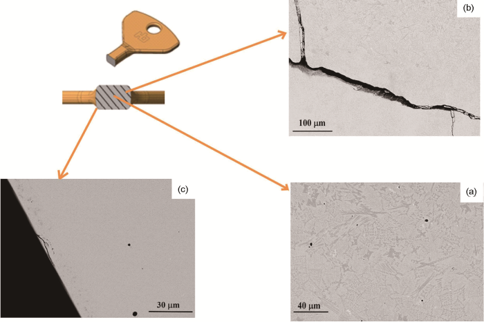
(a) taken at the core of the key, showing a completely crystalline region ...
... (c) taken close to the outer surface, showing a completely glassy part of the keySEM images of the key cast at 1353 K<sup>[<xref ref-type="bibr" rid="R40">40</xref>]</sup>Fig.4
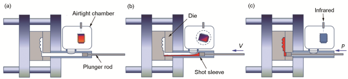
... (c) solidifying under pressure (p—pressure)Illustration of the entire process vacuum high pressure die casting (EPV-HPDC) equipment and operating mode<sup>[<xref ref-type="bibr" rid="R41">41</xref>]</sup>Fig.5
图6a[41]是应用EPV-HPDC技术压铸的边界尺寸约为155 mm × 85 mm × 10 mm,最小厚度约为0.5 mm的Zr55Cu30Ni5Al10 BMG智能手机边框.从图可以看到,该手机框表面光洁、轮廓清晰、形状完整,显示了良好的成形性.但使用三维X射线断层扫描(CT)发现,在手机框的不同部位尚有少量体积小于0.1 mm3的微小空隙缺陷(图6b[41]),这可能是由于充型速度过快使得微小汽泡无法逸出所致.通过计算手机边框中的微小气孔体积,估算出零件的孔隙率约为0.9%,远低于压铸镁基[43]、钙基[44]和镧基[45]非晶合金的孔隙率(孔隙率> 10%). ...
... 图6a[41]是应用EPV-HPDC技术压铸的边界尺寸约为155 mm × 85 mm × 10 mm,最小厚度约为0.5 mm的Zr55Cu30Ni5Al10 BMG智能手机边框.从图可以看到,该手机框表面光洁、轮廓清晰、形状完整,显示了良好的成形性.但使用三维X射线断层扫描(CT)发现,在手机框的不同部位尚有少量体积小于0.1 mm3的微小空隙缺陷(图6b[41]),这可能是由于充型速度过快使得微小汽泡无法逸出所致.通过计算手机边框中的微小气孔体积,估算出零件的孔隙率约为0.9%,远低于压铸镁基[43]、钙基[44]和镧基[45]非晶合金的孔隙率(孔隙率> 10%). ...
... [41]Image of Zr<sub>55</sub>Cu<sub>30</sub>Ni<sub>5</sub>Al<sub>10</sub> bulk metallic glasses (BMGs) smartphone frame and the corresponding runner system (a), and the 3D distribution of the porosity in the smartphone frame (b) (A, B, C, and D denote different regions)<sup>[<xref ref-type="bibr" rid="R41">41</xref>]</sup>Fig.6
(a) BMG transmission used in a notebook computer fabricated by Vit106 ...
... (c) Vit106 thin-walled BMG samples coated in different colors (d-f) biomedical implants fabricated using Vit105 BMGsBMG parts with various shapes and used in different fields<sup>[<xref ref-type="bibr" rid="R41">41</xref>]</sup>Fig.7
(a) suction casting over brass inserts was used to create a cup from a Ti-based BMG ...
... (i) XRD spectra of three BMG alloys cast into flexsplines, showing mostly amorphous microstructure even in fairly large partsPrototyping bulk metallic glass flexsplines, and DSC curves and XRD spectra<sup>[<xref ref-type="bibr" rid="R46">46</xref>]</sup>Fig.8
(a, b) 50 mm and 20 mm diameter BMG flexsplines cast to near net shape from the alloy LM1b. After casting, the samples have been de-gated and holes machined into the bottom (c, d) inserting the BMG flexspline into a commercial steel outer spline (e) a fully assembled hybrid CSG-20 SWG with a BMG flexspline (f) a still from a video of the BMG flexspline being driven by the wave generator after submersion in liquid nitrogen (g, h) testing a fully assembled SWG with a BMG flexspline at liquid nitrogen temperatures (i) example of different BMG alloys cast into flexsplines. In total, four alloys were fabricated commercially, as shown (j) optimal micrographs from the larger 50 mm diameter flexspline comparing the steel part to the cast BMG part (k) images of 20 mm diameter flexsplines from machined steel, machined BMG and two cast BMG (l) a schematic showing approximate cost associated with machining steel flexsplines and casting > 1.0 × 10⁴ BMG flexsplines. BMGs can be cast down to ~20 mm in diameter before thermoplastic forming techniques must be used to achieve micro-sized flexsplines. Multi-part casting is possible at small flexspline dimensions ...
... [46]
(a, b) 50 mm and 20 mm diameter BMG flexsplines cast to near net shape from the alloy LM1b. After casting, the samples have been de-gated and holes machined into the bottom (c, d) inserting the BMG flexspline into a commercial steel outer spline (e) a fully assembled hybrid CSG-20 SWG with a BMG flexspline (f) a still from a video of the BMG flexspline being driven by the wave generator after submersion in liquid nitrogen (g, h) testing a fully assembled SWG with a BMG flexspline at liquid nitrogen temperatures (i) example of different BMG alloys cast into flexsplines. In total, four alloys were fabricated commercially, as shown (j) optimal micrographs from the larger 50 mm diameter flexspline comparing the steel part to the cast BMG part (k) images of 20 mm diameter flexsplines from machined steel, machined BMG and two cast BMG (l) a schematic showing approximate cost associated with machining steel flexsplines and casting > 1.0 × 10⁴ BMG flexsplines. BMGs can be cast down to ~20 mm in diameter before thermoplastic forming techniques must be used to achieve micro-sized flexsplines. Multi-part casting is possible at small flexspline dimensions ...
... (a, b) 50 mm and 20 mm diameter BMG flexsplines cast to near net shape from the alloy LM1b. After casting, the samples have been de-gated and holes machined into the bottom (c, d) inserting the BMG flexspline into a commercial steel outer spline (e) a fully assembled hybrid CSG-20 SWG with a BMG flexspline (f) a still from a video of the BMG flexspline being driven by the wave generator after submersion in liquid nitrogen (g, h) testing a fully assembled SWG with a BMG flexspline at liquid nitrogen temperatures (i) example of different BMG alloys cast into flexsplines. In total, four alloys were fabricated commercially, as shown (j) optimal micrographs from the larger 50 mm diameter flexspline comparing the steel part to the cast BMG part (k) images of 20 mm diameter flexsplines from machined steel, machined BMG and two cast BMG (l) a schematic showing approximate cost associated with machining steel flexsplines and casting > 1.0 × 10⁴ BMG flexsplines. BMGs can be cast down to ~20 mm in diameter before thermoplastic forming techniques must be used to achieve micro-sized flexsplines. Multi-part casting is possible at small flexspline dimensionsCommercial casting of BMG flexsplines<sup>[<xref ref-type="bibr" rid="R46">46</xref>]</sup>Fig.9<strong>4 </strong>非晶合金铸造成形的其他方法<strong>4.1 </strong>水冷铜坩埚感应熔炼铜模铸造成形


