


纳米压痕仪是一种先进的测试材料表面力学性能的仪器,被广泛用于研究微米、亚微米及纳米级材料的机械性能[1,2,3,4]。由于连续刚度测量(continuous stiffness measurement,CSM)技术可以在非常小的穿透深度下得到压痕深度与纳米硬度的关系曲线,因此,经常被用于测量离子束辐照材料损伤层纳米硬度的变化[5,6,7]。在测试过程中当压痕深度大于几十纳米时,材料的纳米硬度会随着压痕深度的减小而增加,这种现象被称为压痕尺寸效应(indentation size effects,ISE)。为了解释这种现象,Nix和Gao[8]在1998年提出了一个基于几何必须位错(geometrically necessary dislocation,GND)概念的模型,建立了用材料的体积当量硬度(H0)表示纳米硬度(H)的关系式。在进行纳米压痕实验时,压头尖端周围会形成一个近似半球形的塑性影响区(plasticity affected region,PAR),当PAR的半径大于辐照损伤层的厚度时,测量结果不可避免地会受到基体纳米硬度的影响[9,10,11],故Nix-Gao模型[8]仅在未辐照样品或者是在均匀材料中才可与实验结果很好地吻合。为了表征离子辐照样品损伤层纳米硬度的变化,Kasada等[12]在Nix-Gao模型[8]的基础上提出了一种利用纳米硬度来外推离子辐照损伤层本征硬度的方法。近年来,研究人员试图通过建立相关模型来模拟压痕深度与纳米硬度的关系曲线,如Xiao和Yu[13]建立了线性模型和平方叠加模型,通过比较发现,平方叠加模型能够更好地拟合离子辐照样品纳米压痕的实验结果;Kareer等[14]假设离位损伤剂量与辐照硬化之间存在一个简单的幂律关系,结合体积分数模型给出了纳米硬度与压痕深度之间的关系曲线。上述研究均对辐照材料的纳米硬度进行了测试分析,但没有给出一个简单的方法来拟合出纳米硬度的实验结果。
1 实验方法
块体Hastelloy N合金首先被切成10 mm×5 mm×1 mm的片材,依次用SiC砂纸和Al2O3悬浮液进行机械抛光,接下来用电解抛光去除样品表面应力,最后用50%的丙酮和50%的无水乙醇(体积分数)混合液进行超声波清洗。本工作中的辐照实验在中国科学院近代物理研究所320 kV高压高电荷态离子综合研究平台上完成。在室温条件下,利用7 MeV的Xe26+辐照Hastelloy N合金,辐照剂量分别为1.83×10¹⁴、3.65×10¹⁴和1.10×10¹⁵ ions/cm2,利用SRIM (stopping and range of ions in matter)软件计算各个辐照样品中离位损伤随深度的分布。辐照后的样品在G200型纳米压痕仪上测试其纳米硬度,所选用压头为金刚石材质的Berkovich压头,应变率为0.05 s-1。该仪器的工作原理是利用Oliver和Pharr[17]的方法,通过分析载荷-位移(P-h)曲线给出纳米硬度。压痕最大深度设置为1400 nm,以覆盖整个辐照损伤层的深度。为了保证实验的可靠性,每个样品测试10个压痕点求取其平均值,每2个压痕点之间的距离大于80 μm。利用Axio Imager.M2m金相显微镜(OM)观察压痕形状。
2 实验结果及讨论
图1为辐照剂量分别为1.83×10¹⁴、3.65×10¹⁴和1.10×10¹⁵ ions/cm2的辐照样品中离位损伤随深度的分布图。可见,其对应的离位损伤峰值分别为0.5、1.0和3.0 dpa。图2是进行纳米压痕实验后压痕形状的OM像。可看出压头在试样表面压入形成了一个外轮廓为近三角形的压痕。图3为各个样品的平均纳米硬度与压痕深度的关系曲线图。考虑到压头尖端几何结构的不确定性、压头尖端周围的应变率效应以及其它表面影响因素如表面污染等[18,19],均会影响样品浅表面区域纳米硬度的测量,因此本工作忽略深度小于100 nm 的纳米硬度数据。从图3中可以看出,与未辐照样品的平均纳米硬度相比,3个辐照样品均出现了硬化现象,且辐照损伤剂量在0.5~3.0 dpa这一范围内,辐照样品的纳米硬度与深度关系曲线基本重合,这说明存在硬化饱和现象,这个结果与Chen等[20]的研究结果相似。在Nix-Gao模型[8]中,材料的纳米硬度可以用下式表示:
图1
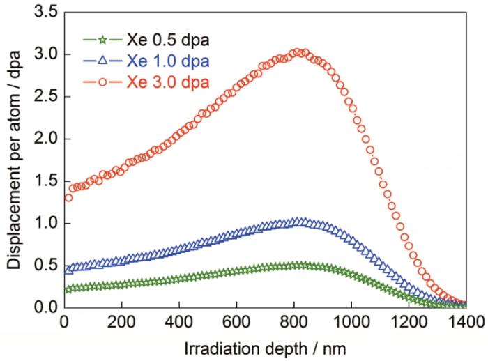
图1
辐照样品中离位损伤随深度的分布图
Fig.1
SRIM calculation of the damage profiles as a function of the depth for irradiated samples (SRIM —stopping and range of ions in matter)
图2

图2
进行纳米压痕实验后试样的压痕形状OM像
Fig.2
OM image of indentation shape of sample after nanoindentation experiment
其中,HMeasured为实验测得的纳米硬度,H0是无限深度处的纳米硬度(体积当量硬度),h*是特征长度,h为压痕深度。利用Kasada等[12]开发的方法,在Nix-Gao模型[8]的基础上,做出H2-h-1的关系图,如图4所示。图中实线是根据最小二乘法拟合出来的,可以看出,未辐照样品的数据点近似为一条直线,而辐照样品的数据点则呈双线性关系。对于辐照剂量为0.5、1.0和3.0 dpa的样品,相应曲线分别在压入深度为256、258和266 nm处发生转折,这是由于软基体效应(softer substrate effects,SSE)造成的。在转折点(hc)处,软基体开始对纳米硬度有贡献,转折点对应的深度大约为辐照损伤层厚度的1/6~1/5,这与前期的研究结果[21,22]相符。根据H2-h-1关系曲线的截距和斜率可以求出各个样品的H0和h*,所得结果见表1。
图3
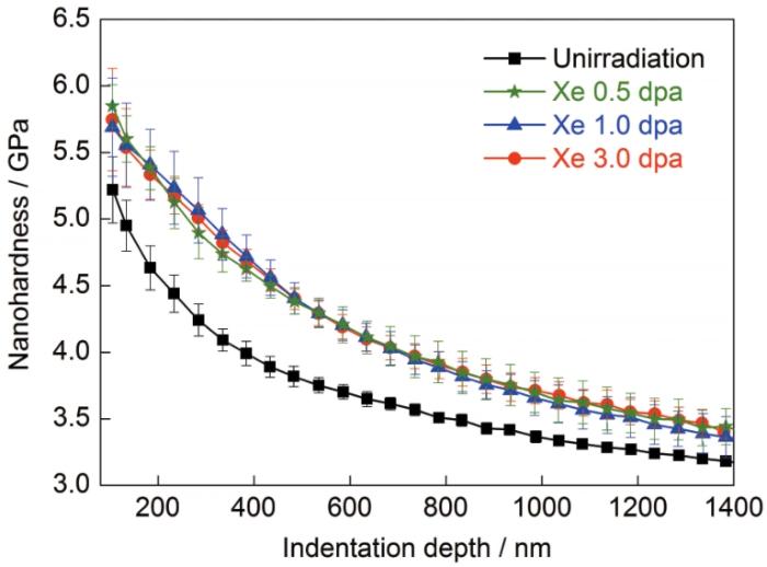
图3
离子辐照前后各个样品的平均纳米硬度随压头压入深度变化的曲线
Fig.3
Indentation depth dependence of the average nanohardness of the unirradiated and irradiated samples
图4
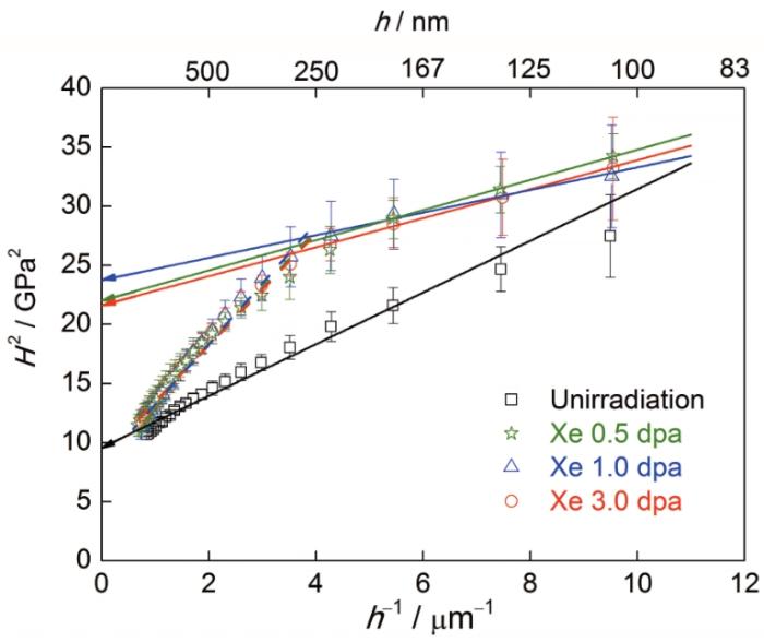
图4
离子辐照前后各个样品的H2-h-1的关系曲线
Fig.4
Curves of H2-h-1 for average nanohardness of the unirradiated and irradiated samples (H—nanohardness, h—indentation depth)
表1 各个样品的H0及h*的值
Table 1
| Sample | H0 / GPa | h* / nm |
|---|---|---|
| Unirradiated | 3.10 | 228 |
| Xe 0.5 dpa | 4.69 | 58 |
| Xe 1.0 dpa | 4.87 | 40 |
| Xe 3.0 dpa | 4.65 | 57 |
其中,HNG是基于Nix-Gao模型[8]利用H0和h*的平均值计算得到的纳米硬度。
图5
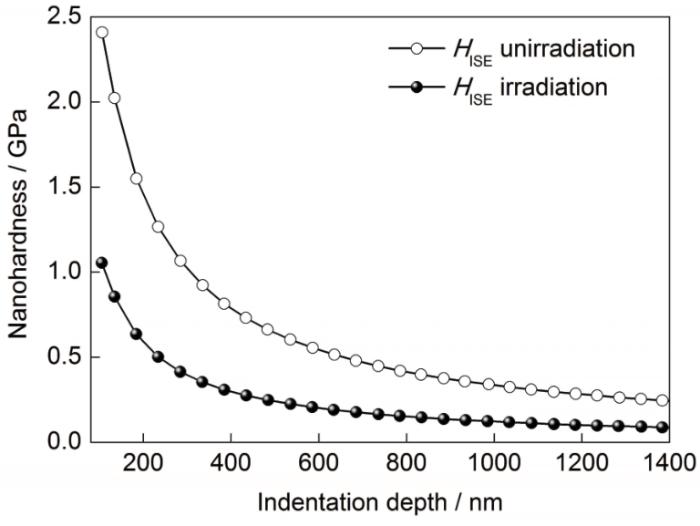
图5
未辐照样品和辐照样品的压痕尺寸效应
Fig.5
The indentation size effects for the unirradiated and irradiated samples (HISE—the indentation size effect)
式中,b是Burgers矢量模,α是一个经验常数,θ是锥形压头表面与被压样品表面之间的夹角,μ是样品的剪切模量。
由图3及各个辐照样品H0的计算结果可知,在本工作中的辐照剂量范围内(0.5~3.0 dpa),辐照硬化处于饱和状态,因此可以合理地假设辐照损伤层和基体的纳米硬度分别为4.74和3.10 GPa。利用纳米压痕仪测量样品纳米硬度的示意图见图6。当压头进入样品后,在压头下方会形成一个近似半球形的塑性影响区[24],也即实验中测得的某一深度处的纳米硬度实际代表该深度以下整个塑性区域的综合纳米硬度。随着压头压入深度的增加,塑性影响区半径(R)将逐渐增大,当R>I (I为辐照损伤层的厚度)时,所测得的纳米硬度除了包含HISE以外,剩余部分是辐照损伤层的纳米硬度与基体纳米硬度的叠加。这个叠加值可以用VLM模型表示[15,16]:
式中,HVLM是用VLM模型计算的纳米硬度;HUnirr.和HIrr.分别是未辐照和辐照样品的H0;T是塑性影响区的半径与辐照损伤层厚度的差值;a是塑性影响区中基体的体积分数;半球形塑性影响区的体积
图6
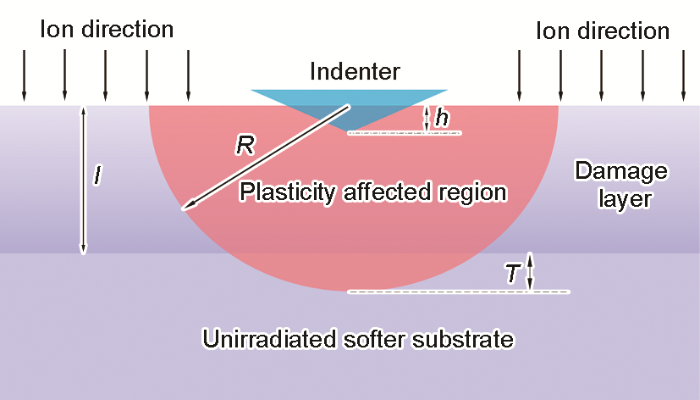
图6
纳米压痕仪测量样品纳米硬度的示意图
Fig.6
Schematic drawing of the nanohardness measurement (I—the thickness of irradiation damage layer, R—the radius of plasticity affected region, T—the difference between R and I)
图7
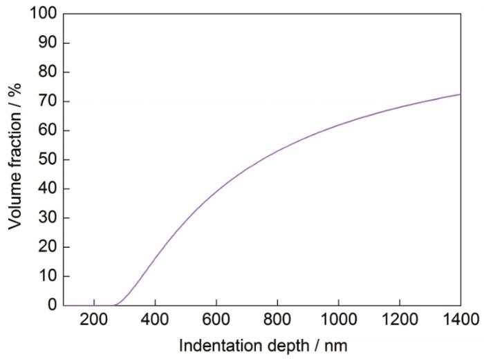
图7
塑性影响区中基体的体积分数
Fig.7
Calculated volume fraction of matrix in the plasticity affected region
将相应的纳米硬度及尺寸效应代入式(7):
图8
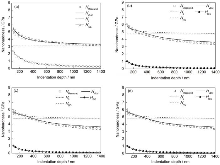
图8
利用模型(VLM模型和Nix-Gao模型)计算出来的纳米硬度与实验测得的纳米硬度对比图
Fig.8
Comparison of nanohardness calculated by different models with the measured nanohardness of the samples before (a) and after Xe26+ ion irradiation with 0.5 dpa (b), 1.0 dpa (c) and 3.0 dpa (d) (HMeasured—the measured nanohardness, HVLM—the nanohardness calculated by VLM model, H0—the nanohardness in the limit of infinite depth, HNG—the nanohardness calculated by Nix-Gao model)
其中,EUnirr.和EIrr.分别是未辐照样品的Young's模量和辐照样品辐照损伤层的Young's模量。根据纳米压痕的测试结果,EUnirr.和EIrr.的平均值分别为226和234 GPa。将相应的Young's模量和纳米硬度代入式(9),得到
图9
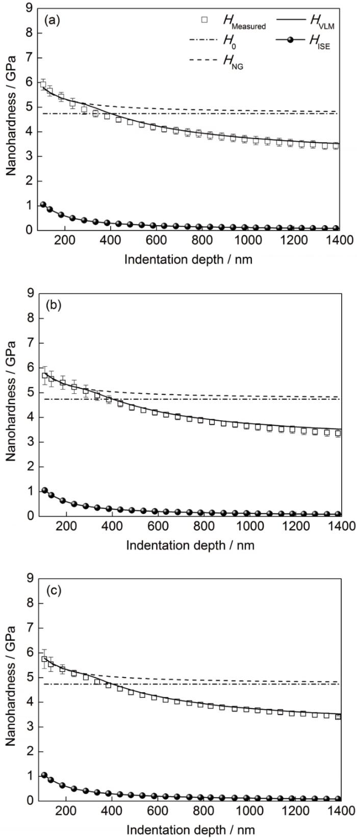
图9
改进后的VLM模型计算出来的纳米硬度与实验测得的纳米硬度对比图
Fig.9
Comparisons of nanohardness calculated by the modified VLM model with the measured nanohardness of the samples after Xe26+ ion irradiation with 0.5 dpa (a), 1.0 dpa (b) and 3.0 dpa (c)
式中,
3 结论
(1) 由于辐照产生的缺陷会阻碍位错线的滑移,3个辐照样品的纳米硬度均大于未辐照样品的纳米硬度,且在本工作中样品遭受的辐照剂量范围内(0.5~3.0 dpa),辐照硬化处于饱和状态。
(2) 辐照样品的H0大于未辐照样品的H0,这使得辐照样品的纳米硬度对压痕深度的依赖性减小,即辐照样品的压痕尺寸效应小于未辐照样品的压痕尺寸效应。
(3) 对于辐照样品来说,当压头的压入深度大于临界深度时,塑性影响区并非是一个半球形的区域。基于此,参考涂层材料硬度的处理方法,在VLM模型中引入“界面参数”
参考文献
A model to evaluate the nano-indentation hardness of ion-irradiated materials
[J].
Synergistic effects on microstructural evolution and hardening of the Hastelloy N alloy under subsequent He and Xe ion irradiation
[J].
TEM, XRD and nanoindentation characterization of xenon ion irradiation damage in austenitic stainless steels
[J].
A promising new class of irradiation tolerant materials: Ti2ZrHfV0.5Mo0.2 high-entropy alloy
[J].
Evaluation of radiation hardening in ion-irradiated Fe based alloys by nanoindentation
[J].
Nanoindentation hardness and its extrapolation to bulk-equivalent hardness of F82H steels after single- and dual-ion beam irradiation
[J]. J
Nanostructure variations and their effects on mechanical strength of Ni-17Mo-7Cr alloy under xenon ion irradiation
[J].
Indentation size effects in crystalline materials: A law for strain gradient plasticity
[J].
Nanoindentation on V-4Ti alloy irradiated by H and He ions
[J].
Evaluation of irradiation hardening and microstructure evolution under the synergistic interaction of He and subsequent Fe ions irradiation in CLAM steel
[J].
The studies of irradiation hardening of stainless steel reactor internals under proton and xenon irradiation
[J].
A new approach to evaluate irradiation hardening of ion-irradiated ferritic alloys by nano-indentation techniques
[J].
Comparison of linear and square superposition hardening models for the surface nanoindentation of ion-irradiated materials
[J].
An analytical method to extract irradiation hardening from nanoindentation hardness-depth curves
[J].
Issues to consider using nano indentation on shallow ion beam irradiated materials
[J].
The mechanical properties of wear-resistant coatings: I: Modelling of hardness behaviour
[J].
An improved technique for determining hardness and elastic modulus using load and displacement sensing indentation experiments
[J].
Xenon ion irradiation induced hardening in inconel 617 containing experiment and numerical calculation
[J].
Hardness measurements of Ar+-beam treated polyimide by depth-sensing ultra low load indentation
[J].
The irradiation hardening of Ni-Mo-Cr and Ni-W-Cr alloy under Xe26+ ion irradiation
[J].
Defects evolution and hardening in the Hastelloy N alloy by subsequent Xe and He ions irradiation
[J].
An experimental investigation of the deformed zone associated with indentation hardness impressions
[J].
Relationship between damage and hardness profiles in ion irradiated SS316 using nanoindentation―Experiments and modelling
[J].
Evaluation of helium effect on ion-irradiation hardening in pure tungsten by nano-indentation method
[J].
Correlation of process and system parameters with structure and properties of physically vapour-deposited hard coatings
[J].
