


限制热作模具寿命的主要因素包括热疲劳、侵蚀、整体开裂等,其中热疲劳裂纹是热作模具最常见的失效形式[3]。Zhang等[4]对用于挤压铸造45#钢的H13钢冲头研究表明,冲头存在51 MPa的摩擦剪切应力和29 MPa的流动应力。Sjöströ等[5]对H13钢制备的压铸和热锻模具的热疲劳裂纹研究表明,表面应力集中是裂纹萌生的主要原因。Delagnes等[6]研究了温度和初始硬度对5%Cr (质量分数)模具钢失效行为的影响,发现存在非金属夹杂、母相奥氏体晶界以及板条边界3种主要的裂纹形核位置。Meng等[7]研究表明,H13钢的初始组织为细晶马氏体,经过热疲劳实验后转变为粗晶马氏体和大量粗化的碳化物,其中晶界处粗化的碳化物导致裂纹萌生。热循环过程中H13钢试样边缘存在高的轴向应力,促使萌生的热裂纹沿着垂直于试样轴向的方向扩展并导致失效[1]。因此,研究应力状态下H13钢的裂纹萌生和扩展行为,有助于揭示H13模具钢的断裂机制,为提高H13钢的热疲劳抗力提供依据。
外加应力作用下,材料积累的弹性能会引发塑性形变的耗散过程。合金的塑性形变机制主要包括位错滑移、孪晶形变和应力诱导相变。其中,应力诱导相变在相变诱导塑性(transformation-induced plasticity,TRIP)钢[8,9]中有显著的应用。相关研究[10]表明,TRIP钢中残余奥氏体的应力诱导马氏体相变提供了高加工硬化率,从而有效提高了TRIP钢的强韧性。例如董瀚等[11]研究表明,含30% (体积分数)亚稳奥氏体且具有超细基体的双相组织钢,可获得室温抗拉强度0.8~1.6 GPa,断后伸长率30%~45%,强塑积达到30~48 GPa·%的优异性能。Cai等[12]研究表明,中锰钢中的非均匀分布的Mn元素导致组织中存在稳定性不同的奥氏体,从而获得了不连续的TRIP效应及铁素体的协调变形。因此,通过改进调质处理工艺调控H13钢组织中残余奥氏体的形态和分布,发挥残余奥氏体的应力诱导相变效应,是提高H13钢强韧性的可行思路。
近年来,原位透射电镜(in situ TEM)观察技术成为研究材料组织演化的重要表征手段[13]。其中,原位TEM拉伸不仅能直观地研究材料形变过程中的位错运动、晶界迁移以及位错和析出物的交互作用[14~16],而且可以表征材料形变过程中发生的应力诱导相变。例如Manchuraju等[17]发现固溶时效处理NiTi单晶随着[110]B2晶向的应变增加,其马氏体板条形核并生长到几微米厚度。Yao等[18]发现亚稳态β钛合金存在α''马氏体转变、{112}<111>β孪生形变和α''薄片扭折3种塑性形变机制。Zárubová等[19]发现CuAlNi单晶发生马氏体相变后,在奥氏体和2H马氏体的单个变体间存在平面界面。此外,Zhong等[20]发现大角度晶界、小角度晶界和马氏体/奥氏体(M/A)岛薄片均能阻碍裂纹扩展。因此,应用TEM的原位拉伸手段研究H13钢塑性形变过程中的组织演变、裂纹萌生和扩展,有助于从微观角度揭示H13钢组织的塑性形变行为以及断裂机制。
本工作采用原位TEM拉伸结合离位电子背散射衍射(EBSD)分析的表征手段,研究了稀土H13钢(除稀土外,主要合金元素含量基本符合GB/T 1299-2000的H13钢成分要求)在拉伸过程中组织的形变行为和断裂机制,重点探讨了组织中的裂纹萌生和扩展行为、位错运动以及残余奥氏体的应力诱导相变效应,明确了大角度晶界和残余奥氏体可有效阻碍裂纹的扩展。
1 实验方法
采用电渣重熔工艺制备稀土H13钢,采用的稀土渣系成分配比(质量分数)为:30%RExOy (85%La2O3+15%CeO)+20%CaO+50%CaF2。电渣重熔的工艺参数为:工作电流2300 A,工作电压28.0 V,结晶器冷却水流量2.14 m3/h,水冷底座水流量1.74 m3/h。所获得的稀土H13钢的化学成分(质量分数,%)为:C 0.41,Cr 5.08,Si 0.80,Mo 1.01,Mn 0.38,V 0.78,S 0.002,P 0.019,RE 0.01,Fe余量。
将所得稀土H13钢铸锭进行热锻,热锻工艺为:1200 ℃保温3 h后进行自由锻造,终锻温度≥950 ℃,锻比≥6。将热锻后的稀土H13钢进行等温球化退火处理:在箱式电阻炉中加热到900 ℃保温1.5 h,降温到740 ℃保温3.0 h,随炉以<50 ℃/h的冷速冷却至450 ℃以下,再出炉空冷至室温。将等温球化退火后的试样在1030 ℃保温30 min后油淬至室温。对淬火处理试样进行高温预回火+二次回火处理:640 ℃保温10 min出炉空冷,600 ℃保温30 min出炉空冷。
将热处理所得试样按照如图1所示的尺寸加工成12.5 mm×2.5 mm×0.4 mm的长方形薄片状试样。使用SiC砂纸将试样厚度打磨至40 μm左右,采用电解双喷减薄仪对试样中心区域进行减薄,电解液成分为5% (质量分数)的高氯酸酒精,采用35 mA恒电流电解,液氮冷却温度控制在‒10~‒15 ℃,试样中心区域表面出现穿孔(图1圆圈标识区域)即取出并用酒精浸泡。采用GATAN654单倾拉伸附加装置加载外加应力,单倾侧入拉伸杆的恒速伸长率范围为0.01~1 μm/s,通过按钮手动控制停止和启动伸长,拉伸实验在室温条件下进行。采用Tecnai F20型TEM对试样在拉伸过程中的微观结构变化和裂纹扩展情况进行观察。
图1
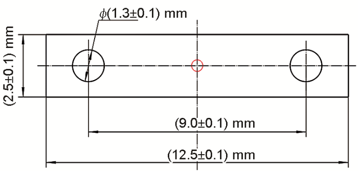
图1
原位拉伸试样形状和尺寸
Fig.1
Shape and size of in situ tensile specimen (Circle in the middle of specimen shows the location of central double-jet electropolishing perforation)
原位拉伸结束后取出试样,采用配备了EBSD系统的Mira3 LMH热场发射扫描电镜(SEM)对试样的微观组织进行表征,扫描步长为0.05 μm,采集多个区域进行后续分析。采用HKL-Channel5软件对于所得离位EBSD取向数据作降噪等预处理,采用HKL-Channel5和Beausir等[21]开发的ATEX软件进行后续EBSD数据分析。根据所获得的EBSD数据计算得到位向关系,可以进行母相奥氏体取向重构,进而计算重构奥氏体晶粒内V1与其它变体构成的变体对的晶界长度分数(length fractions of inter-variant boundaries),即V1与其它变体构成的变体对的晶界长度占该晶粒内马氏体总晶界长度的比例,该值反映变体对含量(fraction of variant pairs)[22~25]。本工作在Bachmann等[26]开发的MTEX算法的基础上,参考Nyyss
2 实验结果与讨论
2.1 稀土H13钢热处理试样的微观结构
图2
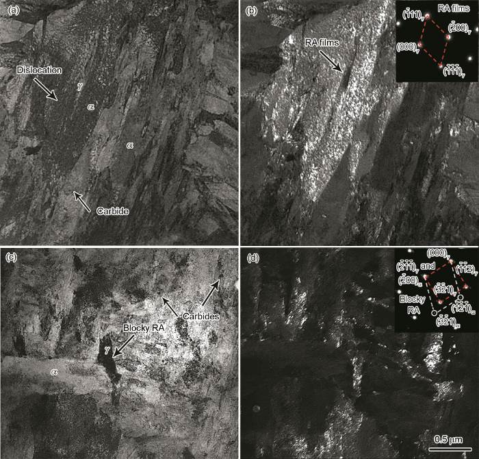
图2
稀土H13钢热处理试样马氏体基体的明场像、暗场像和选区电子衍射(SAED)花样
(a, b) retained austenite films (c, d) blocky retained austenite
Fig.2
Bright-field (a, c) and dark-field (b, d) TEM images of rare earth H13 steel specimen after heat treatment (RA—retained austenite. Insets in Figs.2b and d show the selected area electron diffraction (SAED) patterns)
图3为稀土H13钢热处理试样不同区域组织的TEM明场像。由图3a可见,在马氏体基体中有高密度位错的马氏体板条,马氏体板条内存在位错缠结,存在马氏体晶界处的位错塞积以及150~200 nm的位错胞结构。由图3b可见,晶界处存在尺寸为80~100 nm的颗粒状析出物,且析出物附近有着明显的位错塞积。由图3c可见,在母相奥氏体晶粒的晶界上有明显的位错塞积,在母相奥氏体晶粒内部有贯穿晶粒的孪生马氏体板条。图3c中方框区域放大图见图3d,由图3d可见孪生马氏体的亚结构为纳米级的平行排列的板条,孪生马氏体附近存在颗粒状的碳化物颗粒。由图3e可见,沿着母相奥氏体晶界两侧有着平行排列的马氏体板条,多个马氏体板条呈现出明显的块状(block)结构,并且在晶界左侧可见尺寸约为500 nm的位错胞结构。由图3f可见明显的堆垛层错,在堆垛层错内有平行排列的孪生马氏体板条,在堆垛层错边缘有颗粒状碳化物和高密度的位错缠结。
图3
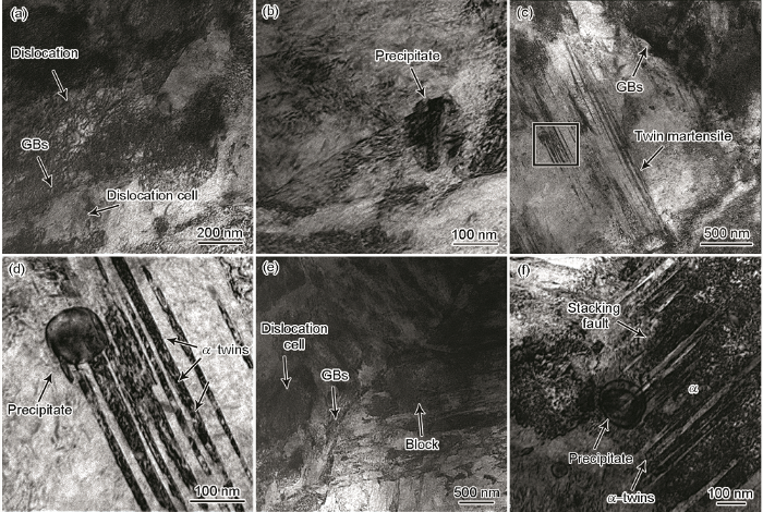
图3
稀土H13钢热处理试样精细组织的TEM明场像
(a) dislocation (b) precipitate (c) twin martensite
(d) enlarged view of square area in Fig.3c (e) GBs (f) stacking fault
Fig.3
Bright-field TEM images of the fine structure of rare earth H13 steel specimen after heat treatment (GBs—grain boundaries)
2.2 原位拉伸试样的微观组织演变和裂纹扩展
2.2.1 裂纹的萌生与扩展
图4
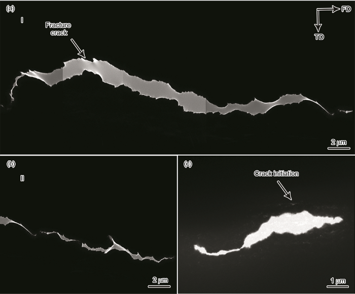
图4
稀土H13钢原位拉伸试样裂纹形貌的TEM像
(a) main crack area I (b) main crack area II (c) secondary crack area
Fig.4
TEM images showing crack morphologies of in situ tensile specimen of rare earth H13 steel (TD—tensile direction, FD—fracture direction)
2.2.2 位错与晶界和析出物的交互作用
图5为拉伸杆行程由48.3 μm增加到110.7 μm时,稀土H13钢原位拉伸试样微观组织形貌演变的TEM像。由图5a可见,应力加载条件下位错运动,并且在母相奥氏体晶粒的晶界位置发生位错塞积,碳化物颗粒附近也发生明显的位错塞积。由图5b~d可见,随着拉伸变形量增大,母相奥氏体晶界左侧晶粒内部出现明显的位错缠结,晶界右侧晶粒中出现位错墙重排等塑性形变的典型特征。由图5e和f可见,随着拉伸变形量进一步增大,在晶界和碳化物附近又出现了明显的位错塞积现象,说明形变过程中晶界和碳化物起到了阻碍位错运动的作用。另外,图5a中晶界处的析出物附近出现微空洞(microvoid),从图5b~e可猜测晶界处位错的运动促进了微空洞的长大,微空洞连接成为微裂纹并沿着晶界扩展;而图5f中微裂纹尖端前条状组织衬度相比图5b的衬度明显增加,伴随微裂纹停止扩展。
图5
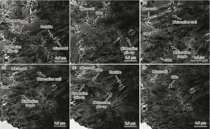
图5
拉伸杆行程由48.3 μm增加到110.7 μm时稀土H13钢原位拉伸试样微观组织形貌演化的TEM像
(a) microvoid initiated from GBs and dislocation pile-up at GBs
(b) dislocations across GBs and dislocation pile-up at carbides (c, d) dislocation wall, dislocation tangle and dislocation cell formed in different grains (e, f) newly formed dislocation pile-up at GBs and carbide
Fig.5
TEM images showing the microstructure evolutions of in situ tensile specimen of rare earth H13 steel during tensile process when tensile displacement increased from 48.3 μm to 110.7 μm (a~f), respectively
图6为稀土H13钢原位拉伸试样的主裂纹附近区域微观组织的TEM像。由图6a可见,沿着三叉晶界处出现了裂纹扩展,并且在其附近晶界处出现了明显的裂纹萌生。由图6b~d可见,条状和球状碳化物附近有明显的位错塞积,说明这些析出物阻碍了位错运动。由图6e和f可见,200 nm大尺寸的碳化物处均有明显的微空洞。原位TEM观察[28,29]表明,不论是韧性材料还是脆性金属间化合物,在加载时裂尖首先会发射位错,等达到平衡时会形成无位错区(dislocation free zone,DFZ),因此图6a中右下角的裂纹附近出现了位错显著减少的区域(箭头所示)。高克玮等[30]和陈奇志等[31]分别提出2种韧性材料裂纹形核扩展的方式:第1种是裂纹尖端钝化,在无位错区域形成微裂纹并快速钝化为空洞,空洞和裂纹相互连接导致韧性断裂;第2种是微裂纹在原裂纹顶端形核并钝化为缺口,新的微裂纹继续在新的裂纹顶端形核并钝化为缺口。由图6c可见沿着晶界处的长条状颗粒析出物出现的一系列的裂纹萌生,因此本实验中微裂纹的形核扩展方式与第1种裂纹尖端钝化类似。图6c中晶界处的裂纹萌生前沿存在无位错区,这些无位错区因为位错的继续发射、增殖和运动而不均匀减薄,在最薄处的应力强度因子临界值最大[28,29]。当应力强度因子临界值与稀土H13钢的原子键合力相近时,无位错区的过饱和空位浓度显著地增加从而形成空位团,空位团逐渐积累形成微空洞,微空洞与附近锯齿状细裂纹相连接形成微裂纹[28,29]。随后微裂纹的长大过程伴随着明显的位错运动(图5),并且有新的微裂纹萌生,这些长大的微裂纹相互连接并与主裂纹连接形成图4a和b中的裂纹形貌。
图6
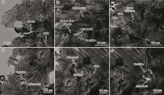
图6
稀土H13钢原位拉伸试样主裂纹附近区域微观组织的TEM像
(a) crack initiated from the triple boundaries and dislocation free zone (DFZ)
(b) dislocation pile-up and microvoid at carbide
(c) DFZ and crack initiations along GBs (d~f) microvoid at carbide with size of 0.2 μm
Fig.6
TEM images of area near main crack of in situ tensile specimen of rare earth H13 steel
对比稀土H13钢热处理试样(图2和3)和拉伸过程中试样(图5和6)的微观组织可得,位错滑移是稀土H13钢塑性形变的主要机制。塑性形变过程中,稀土H13钢的马氏体基体中位错增殖显著增加了位错密度;在晶粒内部发生位错缠结,在母相奥氏体晶界和碳化物析出附近出现位错塞积,这将导致晶界处和析出物处产生较大的应力集中。黄文克等[32]研究发现,00Cr18Ni10N钢丝在冷拔过程中涉及3种变形方式:位错的滑移、孪生与相变,其中孪生片层的产生与增多相当于使基体的晶界数量增加,晶界面积增大,在很大程度上限制了位错的运动并产生加工硬化。因此,稀土H13钢热处理试样在淬火过程发生马氏体相变生成大量的孪生马氏体(图3c和d),这些孪生马氏体在拉伸过程中通过孪晶界阻碍位错运动,降低了位错的平均自由程,从而提高加工硬化率[32]。
2.2.3 残余奥氏体的应力诱导相变效应
图7为稀土H13钢原位拉伸试样主裂纹形貌的SEM像和裂纹边缘选区的离位EBSD分析。由图7a~c可得,主裂纹形貌主要呈“Z”字形的锯齿状。由图7c和d可见,在试样主裂纹附近有尺寸为6~8 μm的粗大颗粒状夹杂物,颗粒状夹杂物所在区域因无法采集Kikuchi花样而出现盲区,夹杂物附近区域由于应力较高导致无法标定。Choi等[33]对中锰钢拉伸变形过程中的裂纹发展和断裂过程的研究表明,造成材料裂纹扩展有3种机制:(1) 在非金属夹杂物处形核并且空隙扩大;(2) 铁素体-马氏体和马氏体-马氏体界面分离;(3) 除了空洞损伤,在断裂试样中观察到沿着奥氏体-铁素体层的纵向解离裂纹形成。结合图4中的“Z”字形的锯齿状裂纹,图6a中沿着晶界萌生的裂纹以及图6f中粗大颗粒状碳化物出现的空隙的扩展,图7c和d中颗粒状夹杂物出现显著的应力集中可得,稀土H13钢组织中的局部晶界处的应力集中和粗大的颗粒状夹杂物是裂纹萌生的主要来源,裂纹易沿着晶界应力集中区域扩展。由图7c~e可得,沿裂纹扩展方向应力导致的EBSD表征盲区逐渐增加;对比可得,沿裂纹扩展方向的高应力区域的残余奥氏体(红色所示)相比低应力区域显著减少,说明在塑性变形过程中试样中沿着晶界分布的残余奥氏体发生应力诱导相变转变成为马氏体。
图7

图7
稀土H13钢原位拉伸试样主裂纹形貌的SEM像和裂纹边缘选区的离位EBSD分析
Color online
(a) left area of central perforation
(b) right area of central perforation
(c) Kikuchi band contrast map of square area in Fig.7b
(d) phase distribution (red: retained austenite, blue: martensite)
(e) inverse pole figure (IPF)
Fig.7
SEM images of main crack and selected area post-mortem EBSD analyses near crack edge of in situ tensile specimen of rare earth H13 steel
图8为稀土H13钢原位拉伸试样主裂纹边缘选区的离位EBSD分析。图8a为采用母相奥氏体取向重构所得的母相奥氏体晶粒分布图,对图中G1和G2区域进行分析。由图8b~g可见,与G1区域相比,G2区域的Kikuchi带衬度对比图灰度增大,说明G2区域的应力更大;G2区域的反极图(IPF)中出现较多的细晶,说明塑性形变过程中由于位错重排导致晶粒碎化;G2区域的相分布图中残余奥氏体(红色)显著减少。相关研究[34]表明,裂纹尖端附近的晶界/孪晶界阻碍导致的位错塞积会促使微空洞形成。在后续塑性应变的作用下,由于微空洞表面发出的位错在运动时会促进空洞的生长和聚集[35]。当裂纹在马氏体板条上传播并在板条边界处遇到薄膜状残余奥氏体时,裂纹可能会继续进入奥氏体引起应力诱导相变生成马氏体,从而消耗裂纹的能量;或者裂纹偏向其它路径,则会导致更长的裂纹路径从而延缓裂纹扩展[36,37]。因此,马氏体板条边界处的薄膜状残余奥氏体可能会捕获裂纹或者抑制裂纹的扩展。由图2可见稀土H13钢的热处理试样的马氏体板条间存在薄膜状的残余奥氏体,晶界附近存在块状的残余奥氏体。由图8可见,相比G1区域,具有相对高应力的G2区域的残余奥氏体显著减少,说明稀土H13钢原位拉伸试样的高应力区域的马氏体晶界处有更多残余奥氏体发生应力诱导相变转变为马氏体。
图8
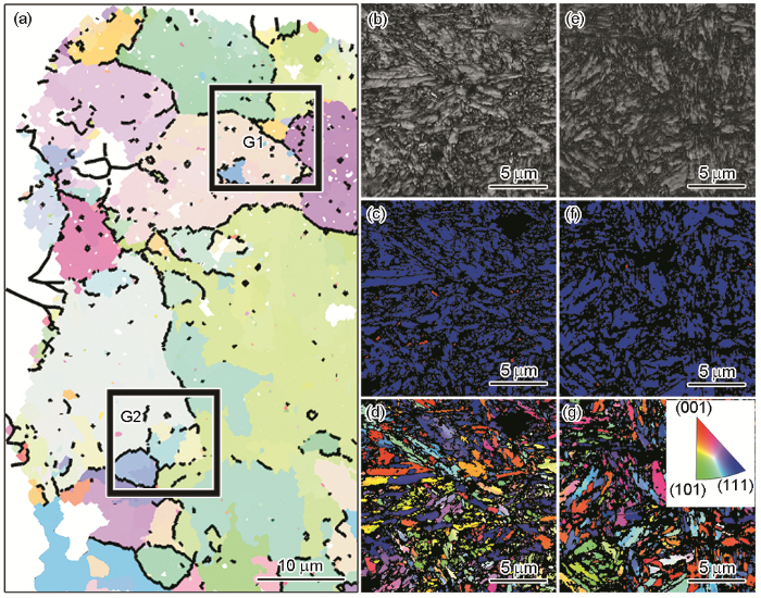
图8
稀土H13钢原位拉伸试样主裂纹边缘G1和G2选区的离位EBSD分析
Color online
(a) parent austenite orientation reconstruction (b, e) Kikuchi band contrast maps (c, f) phase maps (d, g) IPFs
Fig.8
Post-mortem EBSD analyses of selected areas G1 (b~d) and G2 (e~g) near main crack of in situ tensile specimen of rare earth H13 steel
2.3 拉伸形变对马氏体亚结构的影响
图9
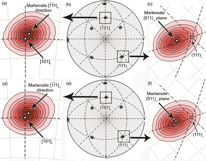
图9
稀土H13钢原位拉伸试样主裂纹边缘G1和G2选区的马氏体和母相奥氏体取向分布
Color online
(a, d) parallel orientation relation between [
Fig.9
Orientation distributions of martensite and parent austenite of selected areas G1 (a~c) and G2 (d~f) in Fig.8a near main crack of in situ tensile specimen of rare earth H13 steel
根据图9所示的马氏体和母相奥氏体的取向关系,对于G1和G2选区的马氏体和母相奥氏体取向重构计算结果见图10。图11为原位拉伸试样主裂纹边缘G1和G2选区的Kikuchi带斜率、孪晶分布和变体分布图。根据相关研究[38],定义晶界取向差为5°~15°的晶界为小角度晶界,晶界取向差为15°~45°或者>45°的晶界定义为大角度晶界。相关研究[39,40]表明,母相奥氏体晶粒内不同层次的马氏体组织可以依次分为束(packet)、块(block)和板条(lath),其中束单元是具有相同惯习面的马氏体变体的块单元的集合,束单元的尺寸被认为是对强度和韧性有贡献的有效晶粒尺寸。由图10可得,在稀土H13钢G1和G2选区分布有密集的块边界(绿线所示)和束边界(红线所示)。对比图10a和图11b、图10d和图11e可得,母相奥氏体晶界、束边界和块边界均为大角度晶界。Morito等[41]发现,束尺寸减小可以有效提高低合金钢的低温韧性。Morris等[42]观察到马氏体的束边界改变了氢致裂纹扩展的路径,起到了抑制裂纹扩展的作用。因此稀土H13钢中母相奥氏体晶界、块边界和束边界等大角度晶界对于裂纹萌生和扩展的阻碍作用是韧性的重要来源。
图10
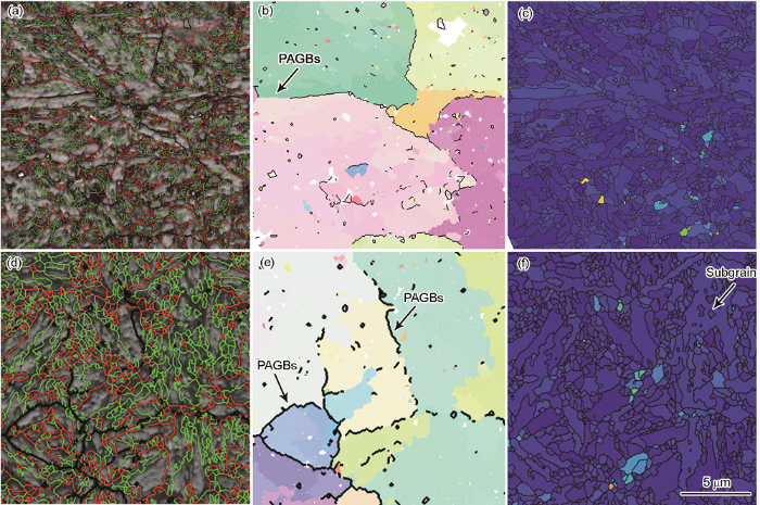
图10
稀土H13钢原位拉伸试样主裂纹边缘G1和G2选区的马氏体和母相奥氏体取向重构计算结果
Color online
(a, d) boundary distributions (b, e) parent austenite orientation reconstructions (c, f) grain maps
Fig.10
Orientation reconstruction results of martensite and parent austenite of selected areas G1 (a~c) and G2 (d~f) near main crack of in situ tensile specimen of rare earth H13 steel (green line: block boundary, red line: packet boundary, black line: parent austenite grain boundary, PAGB)
图11
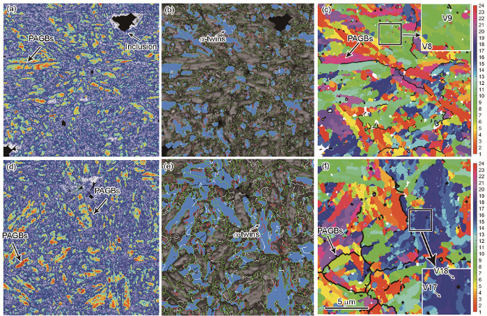
图11
稀土H13钢原位拉伸试样主裂纹边缘G1和G2选区的离位EBSD数据计算结果
Color online
(a, d) band slopes of Kikuchi zone (b, e) twin distribution images (c, f) variant pairs distributions
Fig.11
Post-mortem EBSD data calculation results of selected areas G1 (a~c) and G2 (d~f) near main crack of in situ tensile specimen of rare earth H13 steel (black line: PAGB, white line: 5°<θ<15°, red line:15°≤θ≤45°, green line: θ>45°, color bars of Figs.11c and f show indexes of variant numbers, insets in Figs.11c and f show the indexed variants)
G2选区相比G1选区的形变量较大,因此G2选区的应力分布相对较大。对比图10c和f可知,G2区域中的板条马氏体内细碎的亚晶增加,说明形变量增加促进了马氏体内的位错重排(图5c和d),导致晶粒碎化。对比图10b和图11b、图10e和图11e可知,G2区域沿着母相奥氏体晶界处的孪生马氏体含量增加,孪生马氏体边界均为大角度晶界(如图11b和e中绿线所示),说明形变量增加促进了晶界处孪生马氏体的生成。由图11可知,G2和G1选区的孪晶马氏体均有较低的Kikuchi带斜率,说明在形变过程中孪晶马氏体在外加应力作用下具有相对较高的应力和应变分布;母相奥氏体晶界(PAGBs)处出现V17/V18变体对的孪生马氏体,其附近出现明显的Kikuchi带斜率较高的应力松弛区域。由图11c和f箭头所示可知,图11b和e中相应的孪生马氏体含有V8/V9和V17/V18等变体对,这些变体对均属于V1/V2变体对,即V1/V2构成的具有Σ3重合位置点阵关系的变体对。
根据图9中的实际位向关系,可以计算稀土H13钢试样主裂纹边缘G1和G2区域的V1和其它变体组成的变体对的晶界长度分数,结果见图12。可见,G1和G2不同密排面群的变体对的晶界长度分数的分布基本一致,均有较高的V1/V2、V1/V3&V5变体对含量。Wang等[43]研究表明,V1/V2变体对作为Σ3晶界(孪晶晶界)的来源,具有相对较低的界面能。Lambert-Perlade等[44]研究表明,V1/V2变体对比V1/V4和V1/V8变体对调节相变应变的能力更强,可以有效促进马氏体相变的应变自协调。结合图12,稀土H13钢具有较高含量的V1/V2变体对,说明淬火过程中相变驱动力比较高,需要大量V1/V2变体对进行应变协调,因此在母相奥氏体晶粒内生成平行的孪生马氏体板条(图3c和d)。
图12
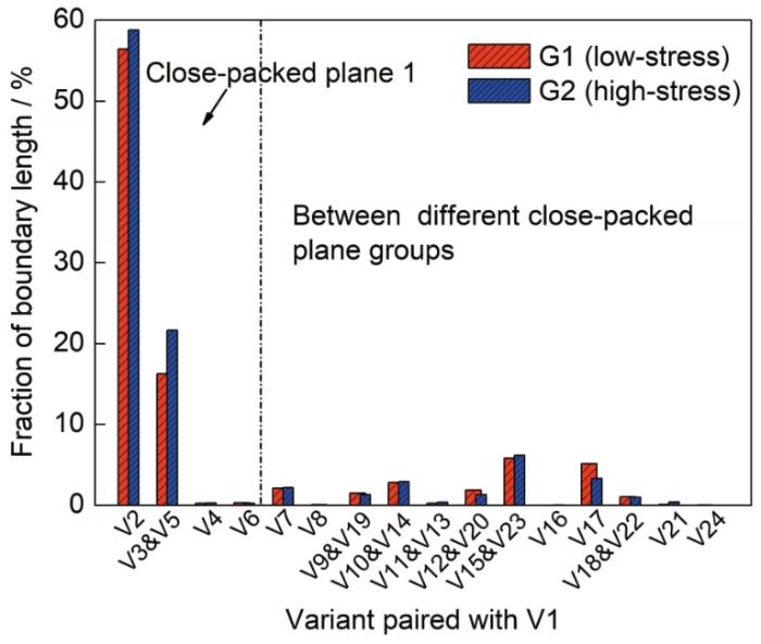
图12
稀土H13钢原位拉伸试样主裂纹边缘G1和G2选区的变体对的晶界长度分数
Fig.12
Length fractions of inter-variant boundaries for selected areas G1 and G2 near main crack of in situ tensile specimen of rare earth H13 steel
从图12可知,低应力的G1区域和高应力的G2区域的V1/V2变体对的晶界长度分数分别为56.5%和58.8%,V1/V3&V5变体对的晶界长度分数分别为16.3%和21.6%。图8中,试样中夹杂物以及晶界应力等导致的衍射花样采集率降低、应力分布不均以及残余奥氏体分布不均匀,这些因素均会给G1和G2区域的V1/V2变体对的晶界长度分数计算带来误差。然而考虑到:(1) 在相同条件下采集和处理G1和G2区域的离位EBSD数据;(2) 具有相对高应力的G2区域相比低应力的G1区域的残余奥氏体显著减少(图8);(3) 具有相对高应力的G2区域相比低应力的G1区域的孪生变体对含量明显增加(图11);(4) G2区域相比G1区域的V1/V2和V1/V3&V5变体对的晶界长度分数增加(图12);(5) V1/V2变体对是孪生马氏体的来源[43],说明存在应力增加促使残余奥氏体转变为V1/V2变体对的现象。因此可以认为G1和G2两者形变的区别导致其V1/V2变体对的晶界长度分数的计算结果差异,而计算结果的差异是上述现象的反映。王世宏等[45]研究发现,γ/ε双相Fe-19Mn合金在拉伸变形过程中,ε-马氏体不仅发生了位错滑移,还形成了{10
3 结论
(1) 稀土H13钢基体内晶界处的应力集中和粗大的颗粒状夹杂物是裂纹萌生的主要来源;拉伸过程中多处裂纹萌生后汇合形成粗大的主裂纹,主裂纹从裂纹源沿着拉伸加载方向的垂直方向扩展到边缘,主要呈“Z”字形的锯齿状特征。
(2) 拉伸试样裂纹边缘的应力分布不均匀,与应力相对较低的区域相比,应力相对较高区域的V1/V2变体对的晶界长度分数从56.5%增加到58.8%,V1/V3&V5的变体对的晶界长度分数从16.3%增加到21.6%。变体对的晶界长度分数的增加表明孪生马氏体含量的提高,可有效缓解晶界处的应力集中,有利于减少裂纹萌生并提高塑韧性。
(3) 拉伸过程中,稀土H13钢晶界处的残余奥氏体发生应力诱导相变。马氏体基体内的位错大量增殖,并在大角度晶界和碳化物析出处形成明显的位错塞积,其中晶界处的位错塞积促进了残余奥氏体的应力诱导相变。
参考文献
Thermal fatigue of materials for die-casting tooling
[J].
Microstructure evolution and kinetic analysis of DM hot-work die steels during tempering
[J].
A multi-layer coating architecture to reduce heat checking of die surfaces
[J].
Abnormal failure analysis of H13 punches in steel squeeze casting process
[J].
Thermal fatigue in hot-working tools
[J].
Influence of testing and tempering temperatures on fatigue behaviour, life and crack initiation mechanisms in a 5%Cr martensitic steel
[J].
Comparison of thermal fatigue behaviour and microstructure of different hot work tool steels processed by biomimetic couple laser remelting process
[J].
Neutron-diffraction study of stress-induced martensitic transformation in TRIP steel
[J].
Supra-ductile and high-strength manganese-TRIP/TWIP steels for high energy absorption purposes
[J].
High-strain-rate behavior of low-alloy multiphase aluminum- and silicon-based transformation-induced plasticity steels
[J].
Microstructure and performance control technology of the 3rd generation auto sheet steels
[J].
The fundamental research and industry trials of the 3rd generation automobile steels was introduced. Motivitated by the theory of microstructure control characterized by Multiphase, Metastable and Multiscale(called M3 simply), summary and review of the home and abroad automobile steels were carried out, which led to the idea microstructure controlling characterized by ultrafine grained matrix and metastable austenite phase and the approaches of medium manganese alloying and austenite reverted transformation annealing for the research and development of the 3rd generation automobile steel. The fundamental research and industry trials were introduced in details, which included the mechanism of austenite reverted transformation, microstructure evolution of the ultrafine grained ferrite and austenite dualphase structure, mechanical behaviors and ductilityenhancing mechanism, industry trial process, service performance and application technologies and prospects of the 3rd generation steels. It was concluded that this study forms the prototype technologies of the third generation automotive sheet steel, which provides the theorical and technological basement for the weightlightening and safetyimprovement of the automotive steels in materials aspect.
第3代汽车钢的组织与性能调控技术
[J].介绍了第3代汽车钢的基础研究与工业试制工作。对国内外高性能汽车钢进行了回顾总结,在以“多相(Multiphase)、亚稳(Metastable)、多尺度(Multiscale)”(简称M3)为特征的组织调控理论的指导下,提出了高强塑积第3代汽车钢的超细晶基体与亚稳相的组织调控思路,采用了新型中锰合金化和逆转变奥氏体(Austenite Reverted Transformation, ART)退火的技术思路。详细介绍了第3代汽车钢的基础研究进展及工业试制结果,内容包括奥氏体逆转变退火机制,超细铁素体与亚稳奥氏体的双相形成规律,高强塑积汽车钢的力学行为及其强塑化机制,第3代汽车钢的工业试制流程及其服役性能和在汽车上应用技术与前景。本研究结果形成了以高强度和高塑性为特征的高塑积第3代汽车钢的原型钢技术,为汽车轻量化与碰撞安全性能的提高奠定了材料技术基础。
Austenite stability and deformation behavior in a cold-rolled transformation-induced plasticity steel with medium manganese content
[J].
Progress and applications of in situ transmission electron microscopy
[J].Recent progress in the application of in situ transmission electron microscopy (TEM) is briefly eviewed. It is emphasized that the development of advanced in situ TEM techniques makes it possible to investigate the volution of materials under heat, strain, magnetic field, electric field or chemical reaction nvironments on the atomic scale. The mechanism of the microstructure evolution under various conditions and the relationship between the atomic structures and their properties can be obtained, which is beneficial for the design of new materials with tailored properties. The clarification of the structure-property relationship will help to develop new materials and solve related basic problems in the field of condensed matter physics.
原位透射电子显微学进展及应用
[J].
In situ TEM observations of reverse dislocation motion upon unloading in tensile-deformed UFG aluminium
[J].Loading unloading cycles have been performed on ultrafine-grained (UFG) aluminium inside a transmission electron microscope (TEM). The interaction of dislocations with grain boundaries, which is supposed to be at the origin of the inelastic behaviour of this class of materials, differs according to the main character of the dislocation segments involved in pile-ups. Pile-ups are formed by spiral sources and lead to the incorporation of dislocations into grain boundaries (GBs) during loading. Upon unloading, partial re-emission of dislocations from GBs can be observed. Stress and strain measurements performed during these in situ TEM loading-unloading experiments are in agreement with the rather large inelastic reverse strains observed during unloading in loading unloading tests on bulk macroscopic UFG aluminium specimens. (C) 2012 Acta Materialia Inc. Published by Elsevier Ltd.
Precipitation strengthening in nanostructured AZ31B magnesium thin films characterized by nano-indentation, STEM/EDS, HRTEM, and in situ TEM tensile testing
[J].
In situ TEM observations of fast grain-boundary motion in stressed nanocrystalline aluminum films
[J].
Pseudoelastic deformation and size effects during in situ transmission electron microscopy tensile testing of NiTi
[J].
In situ scanning and transmission electron microscopy investigation on plastic deformation in a metastable β titanium alloy
[J].
In situ TEM observation of stress-induced martensitic transformations and twinning processes in CuAlNi single crystals
[J].AbstractStress-induced martensitic transformations and twinning processes were studied in thin foils of CuAlNi single crystals strained in situ in a transmission electron microscope. The nucleation and growth of the martensite plates were monitored for three transformation processes known from bulk experiments: (i) the transformation of austenite into 2H martensite at low-stress levels; (ii) the twinning/detwinning processes in 2H martensite; and (iii) the transformation between austenite and 18R martensite at higher stress levels. The morphology of the austenite/martensite habit planes was examined, and the existence of planar interfaces between a single variant of 2H martensite and austenite on the microscopic level was proven.]]>
In situ TEM study of the effect of M/A films at grain boundaries on crack propagation in an ultra-fine acicular ferrite pipeline steel
[J].AbstractMicrostructural refinement of structural materials generally improves their tensile properties but deteriorates their fatigue properties. However, pipeline steels with ultra-fine acicular ferrite (UFAF) possess not only high strength and toughness, but also a low fatigue-crack-growth rate (FCGR) and long fatigue-propagation life. In this paper, the micro-fracture mechanisms of an UFAF pipeline steel are investigated by in situ tensile testing in a transmission electron microscope. The results indicate that a grain-boundary-film structure composed of martensite/austenite could significantly influence the crack propagating behavior in the UFAF steel, consequently lowering the FCGR by enhancing roughness-induced crack closure during cyclic loading.]]>
Spatial correlation in grain misorientation distribution
[J].AbstractGrain misorientation was studied in relation to the nearest neighbor’s mutual distance using electron back-scattered diffraction measurements. The misorientation correlation function was defined as the probability density for the occurrence of a certain misorientation between pairs of grains separated by a certain distance. Scale-invariant spatial correlation between neighbor grains was manifested by a power law dependence of the preferred misorientation vs. inter-granular distance in various materials after diverse strain paths. The obtained negative scaling exponents were in the range of −2 ± 0.3 for high-angle grain boundaries. The exponent decreased in the presence of low-angle grain boundaries or dynamic recrystallization, indicating faster decay of correlations. The correlations vanished in annealed materials. The results were interpreted in terms of lattice incompatibility and continuity conditions at the interface between neighboring grains. Grain-size effects on texture development, as well as the implications of such spatial correlations on texture modeling, were discussed.]]>
Effect of carbon content on variant pairing of martensite in Fe-C alloy
[J].The effect of carbon content on the variant pairing tendency of martensite formed in Fe-C alloys is investigated by means of electron backscattered diffraction analysis. The method used is based on experimentally determined orientation relationships between austenite and martensite. The results show that the carbon content has a strong effect on the martensite variant pairing tendency. This observed change in variant pairing tendency is discussed in relation to the well-known morphological transition from lath to plate martensite in Fe-C alloys and the formation of packets and plate groups. The results indicate that quantitative analysis of variant pairing, as demonstrated here, may facilitate martensite characterization in Fe-C alloys as well as in other alloy systems. (C) 2012 Acta Materialia Inc. Published by Elsevier Ltd.
Effects of transformation temperature on variant pairing of bainitic ferrite in low carbon steel
[J].
Study on welding physical metallurgy behavior of high performance offshore engineering steel
[D].
高性能海洋工程用钢焊接物理冶金行为研究
[D].
New insights into the mechanism of cooling rate on the impact toughness of coarse grained heat affected zone from the aspect of variant selection
[J].
Texture analysis with MTEX-free and open source software toolbox
[J].
Crystallography, morphology, and martensite transformation of prior austenite in intercritically annealed high-aluminum steel
[J].
In situ TEM observations of nucleation and bluntness of nano cracks in thin crystals of 310 stainless steel
[J].
TEM observation of brittle microcrack nucleation of intermetallic compounds
[J].
金属间化合物脆性微裂纹形核的TEM观察
[J].
Nucleation and propagation of microcracks in nanoscale cleavage
[J].
纳米级解理微裂纹的形核和扩展
[J].
In situ observation and study of nucleation of ductile microcracks
[J].
韧断微裂纹形核的原位观察与研究
[J].
Microstructure and mechanical property of cold drawn high strength 00Cr18Ni10N stainless steel wire
[J].ε≦40%), slipping and twinning are the main deformation mechanism, more amounts of twin lamella and dislocation cell microstruture appear, and the tensile strength changes from 600 to 1200 MPa. At the large deformation stage (ε>40%), strain induced martensites begin to take a part of deformation, the microstructure exhibits a fibrous band--like character, its substructure consists of dislocation cell and broken deformation twin with irregular shape, and the tensile strength is above 1200 MPa.]]>
冷拔高强00Cr18Ni10N不锈钢丝显微组织与力学性能
[J].对00Cr18Ni10N(质量分数, %)不锈钢丝进行室温拔制, 获得了不同面缩率的不锈钢丝。拉伸实验、磁性实验与显微组织观察表明, 面缩率小于40%的形变初期阶段, 滑移与孪生是主要的变形方式, 显微组织含大量孪生片层, 亚结构由形变孪晶和位错胞组成, 抗拉强度在600---1200 MPa范围内变化. 面缩率大于40%的大变形阶段, 形变马氏体继孪生之后开始参与变形, 显微组织是纤维状的条带, 亚结构由位错胞与形状不规则、细碎的形变孪晶所组成, 抗拉强度在1200 MPa以上.
Characterization of fracture in medium Mn steel
[J].
Crack propagation mechanisms of AISI 4340 steels with different strength and toughness
[J].
Void growth by dislocation emission
[J].
Effect of substructure on mechanical properties and fracture behavior of lath martensite in 0.1C-1.1Si-1.7Mn steel
[J].
Microstructural evolution in a PH13-8 stainless steel after ageing
[J].AbstractThe precipitation process in a wrought PH13-8 steel during ageing was investigated using a position sensitive atom probe. The precipitates formed are enriched in Ni and Al, and depleted of Fe and Cr, yet the composition is far from the stoichiometric NiAl phase. They may take on different shapes at different temperatures. The hardening effects observed during early stages of ageing should be due to the redistribution of atoms such as Fe, Cr, Ni, and/or Al. Particle coarsening takes place simultaneously with the development of the composition of the NiAl-enriched precipitates. Mo segregation at the precipitate/matrix interface was not found.]]>
Analysis of impact toughness scatter in simulated coarse-grained HAZ of E550 grade offshore engineering steel from the aspect of crystallographic structure
[J].
The morphology and crystallography of lath martensite in Fe-C alloys
[J].AbstractThe morphology and crystallography of lath martensite in Fe-C alloys containing various carbon contents from 0.0026 to 0.61% were studied by analyzing electron back scattered diffraction patterns in scanning electron microscopy and Kikuchi diffraction patterns in transmission electron microscopy. As carbon content increases, the sizes of both packet and block decrease. In low carbon steels (0.0026–0.38%C), a block which is observed as having different contrasts under optical microscopy contains two groups (sub-blocks) of laths which are of two K-S variants with a misorientation of about 10 degrees. On the other hand, in the high carbon alloy (0.61%C), a block consists of laths of a single K-S variant.]]>
Measurement of bainite packet size and its influence on cleavage fracture in a medium carbon bainitic steel
[J].
Effect of austenite grain size on the morphology and crystallography of lath martensite in low carbon steels
[J].
The nature and consequences of coherent transformations in steel
[J].
Grain boundaries in bcc-Fe: A density-functional theory and tight-binding study
[J].
Austenite to bainite phase transformation in the heat-affected zone of a high strength low alloy steel
[J].AbstractThe austenite to bainite phase transformation was investigated in a low alloy structural steel after simulated welding heat treatment, by means of light microscopy, electron backscatter diffraction and transmission electron microscopy. Upper bainite packets result from the growth of groups of laths having close crystallographic orientations but highly misoriented habit planes. Self-accommodation of the transformation eigenstrain was evaluated for various bainite configurations using a micromechanical model. The observed pairs of variants seem to help limiting plastic strain in the austenite phase, thus enhancing growth of the bainite phase during cooling.]]>
