


尽管二硼化物涂层具有高硬度、高耐热能力等优点,但其脆性大,容易开裂甚至脱落,无法服役高强度冲击载荷工况,若向涂层中掺杂C、N等元素可形成蜂窝状纳米复合结构,即非晶原子层包覆纳米尺寸晶粒的三维结构,大量的两相界面可增加微裂纹扩展和位错运动的阻力,实现涂层增韧和强化[8],提升涂层的力学性能、摩擦磨损性能和抗氧化能力[9~11]。Neidhardt等[12]利用弧蒸发技术向Ti-B涂层中掺杂N元素,在高含量N2条件下生成nc-TiN/a-BN结构(nc代表纳米晶,a代表非晶),涂层摩擦系数为0.7~0.8。本课题组前期研究[13]发现,反应沉积Zr-B-N涂层时即使通入极少量N2,也会形成大量a-BN相,而显著降低涂层硬度。因为BN的形成能(-250.3 kJ/mol)远低于金属氮化物的形成能,掺杂的N元素优先与B反应生成软质BN非晶相。为提高涂层硬度,通常采用正向设计方法,即通过补充金属离子和通入大量反应气体(N2)来增加涂层中氮化物硬质相的数量,但同时也增大了涂层中软质非晶相的含量,强化效果不明显。另外,增加靶材溅射功率不仅改变涂层成分,而且增大了溅射粒子的能量,获得的涂层结构更加致密,进而改善涂层性能。喻利花等[14]以不同B靶功率制备系列Zr-B-N涂层,发现随着B靶溅射功率增加,涂层中fcc-ZrBN结构逐渐分解为hcp-ZrB2结构,晶粒尺寸逐渐减小,摩擦系数略有降低。左伟峰等[15]报道了Al靶溅射功率对TiAlN涂层的影响,发现Al靶溅射功率越大涂层组织愈致密,膜基结合力越强。
为进一步提升Ti-B-N涂层的力学性能,若在反应溅射时降低反应气体N2流量,减少涂层中a-BN软质相的含量,增大TiB2靶溅射功率,提高TiB2硬质相的含量,通过形成nc-(Ti2N, TiB2)/a-BN纳米复合结构,有望实现涂层增韧和强化。目前,关于调节TiB2靶溅射功率制备Ti-B-N涂层的研究仍鲜有报道,本工作采用脉冲直流磁控溅射技术研制Ti-B-N涂层,通过改变TiB2靶溅射功率调控涂层成分、结构和性能,系统研究了TiB2靶材溅射功率对涂层微结构和性能的影响机理,为硼氮化物涂层的工程化应用提供理论依据。
1 实验方法
1.1 涂层制备
采用脉冲直流磁控溅射技术在单晶Si (100)片和镜面抛光的SUS304不锈钢、YT硬质合金基体表面沉积Ti-B-N涂层,阴极连接TiB2靶材(纯度99.9%),靶基距为80 mm。将基体放置于酒精(纯度99.5%)中超声清洗20 min,然后使用N2 (纯度99.999%)吹干,最后固定于镀膜室内转架上。在镀膜之前,通入Ar (纯度99.999%)并控制节流阀使工作压强保持在1.4 Pa,施加-800 V偏压,辉光清洗基片10 min。再将偏压降至-50 V,通入反应气体N2,保持工作压强为0.6 Pa,开启TiB2靶电源用于沉积Ti-B-N涂层,所有涂层沉积时间均为360 min。本工作选择TiB2靶溅射功率区间为0.8~2.4 kW,前期实验[13]发现当硼化物靶材溅射功率低于0.8 kW时,通入反应气体N2后,靶表面出现明显钝化、不易起辉,涂层沉积速率显著降低,且性能较差;当硼化物靶溅射功率大于2.4 kW时,所制备的涂层硬度高、脆性大,承载后易开裂,同时镀膜过程中靶材周围热量无法被(冷却水)及时带走,易发生靶材变形甚至烧穿。具体工艺参数详见表1。
表1 不同TiB2靶溅射功率制备Ti-B-N涂层的工艺参数
Table 1
| Parameter | Value | Unit |
|---|---|---|
| Base pressure | 3.0×10⁻³ | Pa |
| Working pressure | 0.6 | Pa |
| Pulsed DC sputtering power (TiB2 target) | 0.8, 1.2, 1.6, 2.0, 2.4 | kW |
| Bias voltage | -50 | V |
| Ar∶N2 flow ratio | 96∶4 | |
| Deposition temperature | 300 | ℃ |
| Substrate rotation speed | 30 | r·min-1 |
| Distance between target and substrate | 80 | mm |
| Deposition time | 360 | min |
1.2 成分分析和结构表征
利用Nano430扫描电子显微镜(SEM)观察不同Ti-B-N涂层的表面和截面形貌;利用EPMA-1600电子探针分析仪(EPMA)定量分析涂层化学成分;利用D8 ADVANCE X射线衍射仪(XRD)分析涂层的物相组成,选用CuKα射线(波长λ=0.154056 nm)进行辐射,衍射角2θ扫描范围为22.5°~80°,扫描步长0.01°。利用聚焦离子束(FIB)制备涂层截面透射电镜样品,使用Tecnai G2 TF20 UT高分辨透射电子显微镜(HRTEM)结合选区电子衍射(SAED)谱识别涂层截面的微观结构信息。上述实验,涂层样品的基体均为Si片。
1.3 性能测试
利用TTX NHT-3纳米压痕仪测试涂层的纳米硬度,基体为单晶Si片,压痕测试选用Berkovich金刚石针尖(弹性模量1140 GPa,Poisson比0.07,针尖直径200 μm),保压时间为10 s,法向载荷5 mN,所有压痕深度均不超过涂层厚度的10%[16],每个涂层样品选取不同位置测试20次,取平均值作为硬度测试结果。采用Anton Paar RST-3划痕仪测量涂层与基体的结合强度,基体为SUS304不锈钢,测试时法向载荷从零逐渐增加到100 N,加载速率为1 N/s,划行速率0.1 mm/s,划痕长度10 mm,借助KEYENCE VHX-1000C光学显微镜(OM)识别涂层开始剥落位置、确定临界载荷,每个涂层样品测试5次取平均值。采用Anton Paar THT球-盘式摩擦磨损试验机测试Ti-B-N涂层的摩擦系数,基体为YT硬质合金,摩擦副选用直径为6 mm的Al2O3球,摩擦实验在室温下进行(相对湿度30%~40%),磨痕直径8 mm,滑动速率0.1 m/s,法向载荷5 N,每个样品旋转3000 r,滑动距离75.4 m,取稳定摩擦阶段的数据计算平均摩擦系数,利用OM观察磨痕形貌。利用D500 Stylus Profilometer轮廓仪测量涂层磨痕横截面积和深度,根据公式W=A/(F·n) (其中,A为磨痕横截面积,F为载荷,n为摩擦圈数)计算涂层磨损率。
2 实验结果与分析
2.1 涂层成分与相结构
图1为不同TiB2靶溅射功率制备Ti-B-N涂层的化学成分。可见,随着TiB2靶溅射功率的增加,涂层中Ti含量由6.0% (原子分数,下同)线性增长至29.2%。因为随着靶溅射功率的增加,单位时间内从靶表面溅射出的Ti、B粒子和TiB2分子数量增多,导致涂层中Ti含量呈增长趋势。而N含量从20.1%下降到4.4%,B含量也从74.0%小幅降至66.5%。这是因为BN的结合能要低于Ti2N和TiB2,在涂层中很容易形成BN相,而低分子量的BN颗粒动能较小,单位时间内沉积到基体表面的粒子数量较少[17]。另外,溅射功率增加使等离子体中Ti、B粒子增多,导致反应气氛中N含量降低,也将引起涂层中N含量降低。
图1
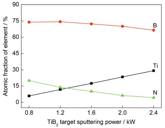
图1
不同TiB2靶溅射功率制备Ti-B-N涂层的化学成分
Fig.1
Chemical compositions of the Ti-B-N coating prepared by different sputtering powers of the TiB2 target
图2为不同TiB2靶溅射功率制备的Ti-B-N涂层的XRD谱。可见,当TiB2靶溅射功率为0.8 kW时,涂层中只出现了(101)取向的Ti2N相衍射峰;当TiB2靶溅射功率逐渐增加至1.6 kW时,Ti2N相衍射峰强度逐渐减弱,并最终消失[18,19]。根据图1可知,此时涂层中的N含量较低,说明镀膜室中的N与B优先反应生成BN相[20],没有剩余N与Ti反应生成Ti2N相,故Ti2N相衍射峰逐渐消失。同时也检测到沿(
图2
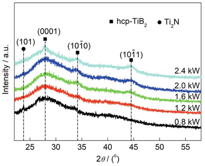
图2
不同TiB2靶溅射功率制备Ti-B-N涂层的XRD谱
Fig.2
XRD spectra of the Ti-B-N coatings prepared by different sputtering powers of the TiB2 target
2.2 微观结构与沉积速率
图3为不同TiB2靶溅射功率制备的Ti-B-N涂层截面和表面形貌的SEM像。由图3a~e可见,所有涂层结构均匀致密,无针孔等缺陷,且与基体结合良好,随着TiB2靶溅射功率增加,涂层厚度逐渐增大。在图3a~c中涂层截面形貌无明显特征,存在的纹理是由于切断试样时受力不均匀所致。由于靶材溅射功率较低时,溅射产物数量少,掺杂N元素后形成大量的非晶BN相,可抑制晶粒生长,起到细化晶粒作用[23]。当靶溅射功率增至2.4 kW时,涂层中出现明显的柱状晶结构,此时溅射产物增多,N元素已完全反应,过量的TiB2溅射颗粒沉积到基体表面,形核并结晶,生长成柱状晶结构。从图3f~j可以看出,当靶材溅射功率较小时,溅射产物少,涂层表面细腻光滑,未出现大颗粒和较大金属液滴。随着靶材溅射功率增加,涂层表面出现大量微小凸起,且边界清晰,分别对应于柱状晶的顶部。一方面,凸起的产生与沉积粒子在基体表面的迁移率密切相关[24],靶材溅射功率增加,加剧了溅射粒子在基体表面的迁移和扩散,晶粒开始生长变大,逐渐形成球状颗粒。另一方面,结合图2可知,尽管所有Ti-B-N涂层中非晶BN相可以起到晶粒细化的作用,但随着TiB2靶材溅射功率增加,涂层中TiB2相含量增多提高了涂层的结晶度,而非晶BN相数量趋于稳定[25],故涂层表面凸起尺寸变大。
图3
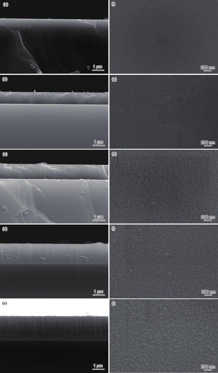
图3
不同TiB2靶溅射功率制备Ti-B-N涂层截面和表面形貌的SEM像
Fig.3
Cross-sectional (a~e) and surface (f~j) SEM images of the Ti-B-N coatings prepared by different sputtering powers of the TiB2 target
(a, f) 0.8 kW (b, g) 1.2 kW (c, h) 1.6 kW (d, i) 2.0 kW (e, j) 2.4 kW
图4
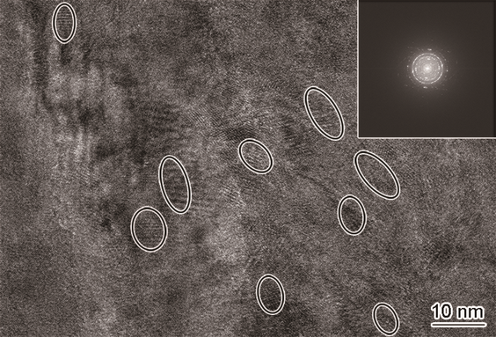
图4
TiB2靶溅射功率为2.4 kW时制备Ti-B-N涂层的HRTEM像和相应的SAED花样
Fig.4
HRTEM image and SAED pattern (inset) for the Ti-B-N coating prepared under a sputtering power of 2.4 kW at the TiB2 target (The zones marked with ellipse represent the TiB2 nanocrystals)
图5
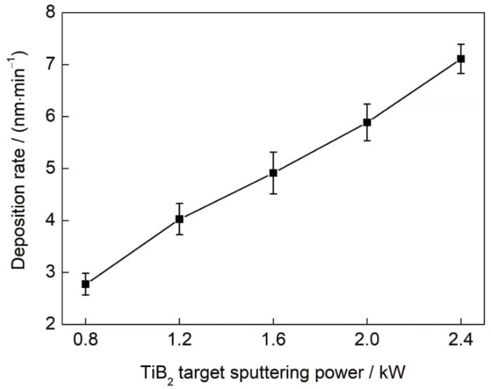
图5
不同TiB2靶溅射功率制备Ti-B-N涂层的沉积速率
Fig.5
Deposition rates of the Ti-B-N coatings prepared by different sputtering powers of the TiB2 target
2.3 涂层的力学性能
硬度是衡量涂层力学性能的重要指标,并受涂层结构、内应力和晶粒尺寸等因素影响[29]。图6为不同TiB2靶溅射功率制备的Ti-B-N涂层的纳米硬度。由图可见,随着TiB2靶溅射功率增加,涂层硬度总体呈上升趋势。当TiB2靶溅射功率为0.8 kW时,硬度较低,约为18.1 GPa,原因在于硼化物涂层的硬度受B—B共价键影响较大;结合图2可知,此时涂层结晶度偏低,且软质BN非晶相含量较高,对涂层硬度产生消极影响。进一步增加靶溅射功率至2.4 kW时,涂层硬度高达33.8 GPa。一方面,TiB2相沿(0001)晶面择优生长,有助于提高涂层硬度;另一方面,纳米晶TiB2相和非晶BN相形成了纳米复合结构,两相界面之间存在较大的内聚能,可阻碍晶粒滑移和位错运动,实现界面强化[30]。
图6
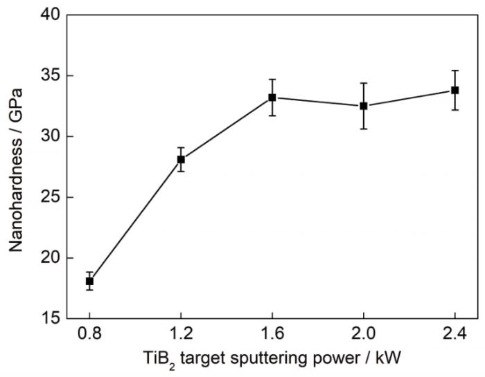
图6
不同TiB2靶溅射功率制备Ti-B-N涂层的纳米硬度
Fig.6
Nanohardnesses of the Ti-B-N coatings prepared by different sputtering powers of the TiB2 target
利用划痕法来判定涂层的膜/基结合力。由于界面性质的差异,涂层和基体的硬度、结构和厚度都影响着临界载荷。图7显示了Ti-B-N涂层的临界载荷随TiB2靶溅射功率的变化趋势。可见,涂层临界载荷在61~86 N范围内变化,并随着TiB2靶溅射功率增加呈现先上升后下降趋势。当靶材溅射功率在0.8~1.6 kW范围变化时,涂层的临界载荷均较高,由于此时涂层内非晶相含量高而晶粒尺寸较小,在复杂应力作用下晶粒越小越容易产生微滑移或倾斜,不利于裂纹萌生、扩展和薄膜剥落,有助于增强膜/基结合力[31]。进一步增加TiB2靶溅射功率至2.4 kW,临界载荷近似线性降至最小值约61 N,靶材溅射功率增加会加剧溅射粒子对基体的轰击效应,使基体的温度升高,热应力的引入在一定程度上可削弱膜/基结合强度[32]。另根据图3可知,此时涂层表面颗粒较大,对应截面已出现柱状晶,在剪切应力作用下会加剧晶粒间滑移、易引起穿晶断裂,裂纹进一步扩展传播导致涂层与基体剥离。
图7
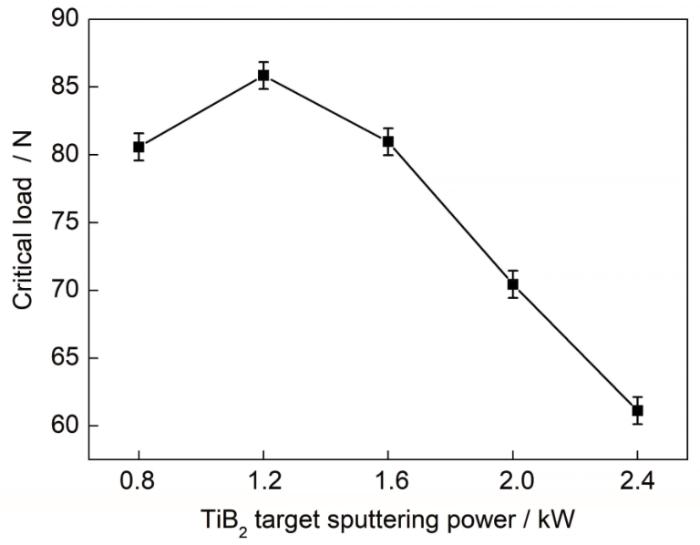
图7
不同TiB2靶溅射功率制备的Ti-B-N涂层的临界载荷
Fig.7
Critical loads of the Ti-B-N coatings prepared by different sputtering powers of the TiB2 target
2.4 涂层的摩擦学性能
图8为不同TiB2靶溅射功率制备的Ti-B-N涂层的平均摩擦系数。可见,随着TiB2靶溅射功率增加,Ti-B-N涂层的摩擦系数呈先降低后增大再下降趋势。当靶材溅射功率较低时,涂层中形成了大量的软质非晶BN相,在摩擦过程中逐渐发生剥落并转移至摩擦界面,具有一定的润滑功能[31]。当溅射功率增至1.2 kW时,涂层内硬质相增多并形成了nc-(Ti2N, TiB2)/a-BN纳米复合结构,涂层硬度和韧性均得到提升,摩擦过程不易出现碎屑剥落,可显著减小对摩副界面摩擦,涂层摩擦系数降至0.58。进一步增加TiB2靶溅射功率至2.0 kW,摩擦系数再次增大。结合物相和硬度分析可知,此时涂层内富含脆性大、硬度高的TiB2相[33],摩擦过程中涂层碎片易发生剥落并逐渐转移至摩擦界面,导致摩擦系数升高。当TiB2靶溅射功率为2.4 kW时,根据图6可知,此时涂层硬度最高,但摩擦系数骤降至最低0.55。研究[34,35]表明,涂层硬度越高对外载荷抵抗能力越强,在稳定摩擦阶段对摩副间接触面积越小,有助于减小摩擦,这也遵循Archard理论[36,37]。可见,Ti-B-N涂层成分、物相组成、硬度等因素均影响其摩擦系数。
图8
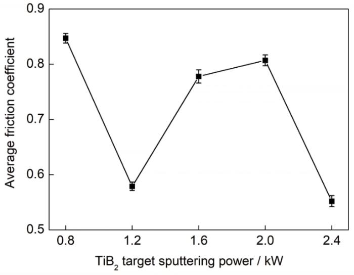
图8
不同TiB2靶溅射功率制备的Ti-B-N涂层的平均摩擦系数
Fig.8
Average friction coefficients of the Ti-B-N coatings prepared by different sputtering powers of the TiB2 target
图9
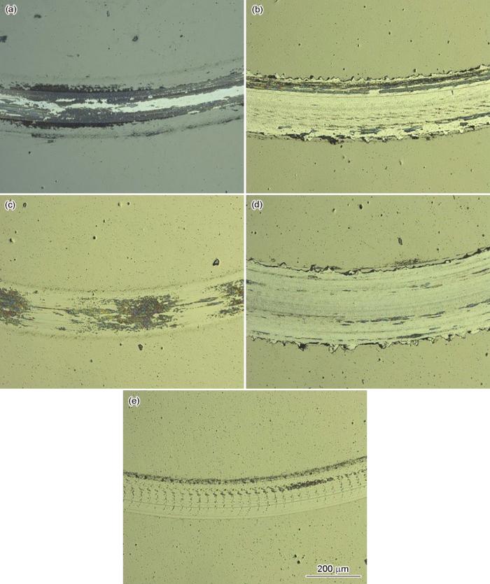
图9
不同TiB2靶溅射功率沉积的Ti-B-N涂层磨痕形貌的OM像
Fig.9
OM images of worn scar of the Ti-B-N coatings prepared by different sputtering powers of the TiB2 target
(a) 0.8 kW (b) 1.2 kW (c) 1.6 kW (d) 2.0 kW (e) 2.4 kW
图10为不同TiB2靶溅射功率沉积的Ti-B-N涂层的磨损率。可见,随着TiB2靶溅射功率增加,涂层的磨损率先增大后减小。当TiB2靶溅射功率为0.8 kW时,涂层已被磨穿无法准确计算磨损率。当靶材溅射功率为2.0 kW时,磨损率较高,约为4.8×10⁻³ μm3/(N·μm),此时摩擦系数也最大,摩擦过程中较大的摩擦力和温升加剧了涂层的磨损,导致磨损率增加,这与磨痕形貌结果相一致。当TiB2靶溅射功率增至2.4 kW时,磨损率降至最低2.1×10⁻⁴ μm3/(N·μm),表现出优异的耐磨性能,此时涂层内硬质相增多,纳米复合结构中大量的两相界面具有增韧和强化作用。另外,涂层硬度高也是其耐磨损的重要原因[41]。
图10
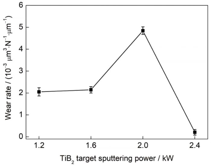
图10
不同TiB2靶溅射功率沉积的Ti-B-N涂层的磨损率
Fig.10
Wear rates of the Ti-B-N coatings prepared by different sputtering powers of the TiB2 target
3 结论
(1) 利用脉冲直流磁控溅射技术研制Ti-B-N纳米复合涂层,通过改变TiB2靶溅射功率调控涂层成分、结构和性能。随着TiB2靶溅射功率增加,涂层结构逐渐由nc-Ti2N/a-BN演变成hcp-TiB2/a-BN,最终以沿(0001)晶面择优生长的TiB2相为主,涂层结晶度逐渐升高。
(2) 随着TiB2靶溅射功率增加,涂层沉积速率近似线性上升;划痕法测得的临界载荷先上升后降低;涂层纳米硬度逐渐增加。当TiB2靶溅射功率为2.4 kW时,涂层硬质相含量最多,纳米硬度高达33.8 GPa,具有良好的力学性能。
(3) 当TiB2靶溅射功率为2.4 kW时,涂层的摩擦系数和磨损率均最低,分别为0.55和2.1×10⁻⁴ μm3/(N·μm),涂层磨痕窄且浅,磨损机理以磨粒磨损为主,涂层具有良好的减摩和耐磨性能。
参考文献
Effect of substrate rotation on structure, hardness and adhesion of magnetron sputtered TiB2 coating on high speed steel
[J].
Nanotribology and surface chemistry of reactively sputtered Ti-B-N hard coatings
[J].
Mechanical characterization of nanostructured TiB2 coatings using microscratch techniques
[J].
Microstructure and properties of TiB2-TiB reinforced titanium matrix composite coating by laser cladding
[J].
Evaluation of TiB2 coatings in sliding contact against aluminium
[J].
Titanium diboride thin films produced by dc-magnetron sputtering: Structural and mechanical properties
[J].
Characteristics of TiB2 films prepared by ion beam sputtering
[J].
Effect of Cu addition on properties of Ti-Al-Si-N nanocomposite films deposited by cathodic vacuum arc ion plating
[J].
Effect of nitrogen content on microstructures and mechanical properties of WB2(N) films deposited by reactive magnetron sputtering
[J].
Thermal stability of superhard Ti-B-N coatings
[J].
Limits to the preparation of superhard nanocomposites: Impurities, deposition and annealing temperature
[J].
Structure-property-performance relations of high-rate reactive arc-evaporated Ti-B-N nanocomposite coatings
[J].
Influence of nitrogen flow on structure and performance of the Zr-B-N films prepared by hybrid magnetron sputtering techniques
[J].
N2流量比对复合磁控溅射Zr-B-N薄膜结构和性能的影响
[J].
Effect of B target power on microstructure, mechanical properties and friction properties of ZrBN composite films
[J].
B靶功率对ZrBN复合膜的微结构、力学性能及摩擦性能的影响
[J].
Effect of sputtering power on micro structure and structure of TiAlN coating
[J].
溅射功率对TiAlN涂层组织结构与性能的影响
[J].
Synthesis and properties of Cr-Al-Si-N films deposited by hybrid coating system with high power impulse magnetron sputtering (HIPIMS) and DC pulse sputtering
[J].
Influence of nitrogen flow ratio on the microstructure, composition, and mechanical properties of DC magnetron sputtered Zr-B-O-N films
[J].
Microstructure and properties of nanocomposite Ti-B-N and Ti-B-C coatings
[J].
Wear-resistant PACVD coatings of the system Ti-B-N
[J].
Microstructure evolution and mechanical properties of Ti-B-N coatings deposited by plasma-enhanced chemical vapor deposition
[J].
Influence of sputtering power on structure and mechanical properties of Zr-B-Nb-N nanocomposite films
[J].
溅射功率Zr-B-Nb-N纳米复合膜结构和机械性能的影响
[J].
Low-stress superhard Ti-B films prepared by magnetron sputtering
[J].
The structure and mechanical and tribological properties of TiBCN nanocomposite coatings
[J].
ZrB2 thin films grown by high power impulse magnetron sputtering from a compound target
[J].
Influences of target poisoning on the mechanical properties of TiCrBN thin films grown by a superimposed high power impulse and medium-frequency magnetron sputtering
[J].
Effect of Cu addition on the microstructure and properties of TiB2 films deposited by a hybrid system combining high power impulse magnetron sputtering and pulsed dc magnetron sputtering
[J].
Growth and properties of amorphous Ti-B-Si-N thin films deposited by hybrid HIPIMS/DC-magnetron co-sputtering from TiB2 and Si targets
[J].
Target poisoning during reactive magnetron sputtering: Part III: The prediction of the critical reactive gas mole fraction
[J].
Design of a separation device used in detonation gun spraying system and its effects on the performance of WC-Co coatings
[J].
Influence of N2 flow rate on structures and mechanical properties of TiSiN coatings prepared by hipims method
[J].
Over the past years, TiSiN coatings have gained increasing importance in the field of cutting tool coatings due to its enhanced hardness and superior oxidation resistance properties produced by the nanocomposite microstructure of TiN nanocrystals embedded in an amorphous Si3N4 matrix. Many methods have been developed to prepare TiSiN coatings, typically named by the DC magnetron sputtering (DCMS) technique and cathodic arc ion plating (AIP), whereas limited studies have been carried out on the deposition of nanocomposite coatings using the high power impulse magnetron sputtering (HIPIMS) approach. The TiSiN coatings were reactively magnetron sputtered in mixed Ar/N-2 precursor gases in a new BERMS system with different flow rate of N-2 in this work. The deposition rate, crystal structure, composition, surface morphology, microstructure and mechanical properties were investigated systematically by surface profilometer, XRD, XPS, SPM, SEM, HRTEM and nano-indentation and the plasma discharge also was studied. The results show that increasing the flow rate of N-2 caused the decrease of deposition rate as expected, accompanying with the change of preferred orientation from (200) orientation to (220) orientation and the decreased compactness, discharge degree and ionization rate. Contrary to the changes of Ti content, Si content gradually increased with increasing the flow rate of N-2, but their changing scale were small. Combined with XRD and XPS analysis, the results indicated that the coatings were composed of crystalline TiN, amorphous Si3N4 and free Si. Besides, free Si disappeared with further increasing the flow rate of N-2. This nanocomposite structure can ultimately be assessed by HRTEM where individual grains and the amorphous regions can be distinguished. In addition, the grain size increased gradually with increasing the flow rate of N-2. Furthermore, both the hardness and elastic modulus linearly decreased with increasing the flow rate of N-2.
N2流量对HIPIMS制备TiSiN涂层结构和力学性能的影响
[J].2流量为10~50 mL/min下沉积TiSiN涂层, 利用台阶仪, XRD, XPS, SPM, SEM, HRTEM和纳米压痕仪对涂层的沉积速率、相结构、成分、形貌和力学性能进行了分析, 并研究了不同N2流量对等离子体放电特性的影响. 结果表明, 在不同N2流量下, TiSiN涂层均具有非晶Si3N4包裹纳米晶TiN复合结构, 涂层表面粗糙度Ra为0.9~1.7 nm; 随N2流量的增加, 等离子体的放电程度减弱, 离化率降低, TiSiN涂层沉积速率降低, 其Ti含量逐渐降低, Si含量逐渐增加, 但变化幅度较小; 涂层择优取向随N2流量的增加发生改变, 晶粒尺寸逐渐增大, 硬度和弹性模量逐渐降低, 涂层硬度最高为(35.25±0.74) GPa.]]>
The relationship between hardness and scratch adhession
[J].
(Ti, Cr)N and Ti/TiN PVD coatings on 304 stainless steel substrates: Wear-corrosion behaviour
[J].
Mechanical properties of TiB2-based nanostructured coatings
[J].
Preparation and tribological properties of Cr-Al-Si-N nanocomposite coatings by three target co-sputtering
[J].
三靶共溅射纳米复合Cr-Al-Si-N涂层的制备及摩擦学性能研究
[J].
CrAlN coatings prepared by HiPIMS/pulsed-DC co-sputtering
[J].
高功率脉冲和脉冲直流磁控共溅射CrAlN薄膜的研究
[J].
Sputtering gas pressure and target power dependence on the microstructure and properties of DC-magnetron sputtered AlB2-type WB2 films
[J].
Design of a separation device used in detonation gun spraying system and its effects on the performance of WC-Co coatings
[J].
The microstructure and mechanical properties evaluation of CrTiAlSiN coatings: Effects of silicon content
[J].
Deposition technology of TiN coatings prepared by arc ion plating
[J].
电弧离子镀TiN涂层沉积工艺研究
[J].
Evaluation of mechanical properties of Ti(Cr)SiC(O)N coated cemented carbide tools
[J].
Study on nanocrystalline Cr2O3 films deposited by arc ion plating: II. Mechanical and tribological properties
[J].
