


Cu/Al层状复合材料综合利用Al轻质、成本低和Cu导电性、导热性良好的优点,实现“以Al节Cu”,可广泛应用于新能源、通讯、电气等行业[1~5]。Cu/Al层状复合材料主要通过轧制工艺进行制备,其加工过程中界面与基体金属材料之间的协同耦合作用是复合板轧制的必要条件,同时也是金属层状复合材料具有不同于单金属材料优异力学性能的基础[6~11]。力学性能是Cu/Al层状复合材料的关键技术指标,Ebrahimi等[12]研究了不同温度下Cu/8011Al/5052Al复合材料的拉伸变形行为,发现Cu层断裂为双剪切断裂模式。在Cu带断裂位置附近,连续的金属间化合物(IMC)发生断裂和分离,在Cu和8011Al界面形成孔洞间隙,Cu层的三重断裂表明,无论采用何种测试温度,Cu层都是在拉伸变形过程中首先发生断裂的母材。在室温拉伸条件下,Cu/8011Al/1060Al三层复合材料中裂纹始终起始于界面金属间化合物内部,并沿应力方向向Cu层扩展直至断裂。相比之下,在Al基体中由于位错相互作用,裂纹发生钝化无法继续扩展,进而使应变累积诱发局部失稳,导致复合材料整体断裂[13]。与双层复合材料相比,Cu/Al/Cu三层复合材料除了具备Cu/Al复合材料的优点外,还通过双层Cu层的设计进一步增强了材料的力学性能、界面结合强度和耐久性,提升了复合材料的整体稳定性和可靠性。然而,关于轧制状态和退火状态下Cu/Al/Cu层状复合材料拉伸性能对比的研究相对较少。
Cu/Al复合材料在导电领域中的应用也面临诸多挑战。在电流传输过程中存在着趋肤效应,即在高频电流下,电子的运动集中在导体表层。目前,对Cu/Al复合材料导电性能的研究主要分为两大类:阻抗研究和Cu/Al复合界面稳定性研究。研究Cu/Al复合材料的阻抗特性,旨在验证其作为导电材料替代Cu的可行性,并考虑Cu与Al物性参数的差异。考虑到趋肤效应,电流在Cu/Al复合材料中的分布情况不同于单一材料,因此计算其有效电阻和阻抗十分重要。黄宏军等[14]对比了Cu/Al/Cu复合板与单一Cu、Al母线排的导电性,发现Cu/Al复合板的电阻率接近单一的Cu板,且高于单一的Al板。这说明Cu/Al复合材料可以代替Cu作为导电材料,实现“以Al节Cu”。王艳艳等[15]发现,Cu/Al双金属复合材料的电阻随着界面金属间化合物厚度的增加而增加,而导电性能下降。罗奕兵等[16]考虑到复合材料界面Cu层的位置分布,发现Cu层位于窄边时复合板的电阻增加系数小于Cu层位于宽边时。此外,Cu/Al复合材料在高压开关柜等设备中服役时,其界面稳定性尤为关键。研究[17,18]表明,在高温、长时载流状态下,Cu/Al界面可能发生组织演变,如界面层厚度增加、界面结合强度下降等。黄宏军等[18]研究了服役条件下的Cu/Al/Cu复合板的界面稳定性,发现在32 h内其复合界面厚度明显增加,而在128 h时趋于稳定,表明复合板作为导电材料使用时其界面稳定性较好,满足导电材料使用要求。左晓姣等[19]对TU1Cu/1050Al冷轧复合板进行通电温升测试,发现经过退火处理后的Cu/Al复合板具有良好的通电温升性能,在通入不同电流时最高温升远小于纯Al,接近于纯Cu。此外,Cu/Al复合板在80 ℃、1000 h时效处理后的电导率和剥离强度未发生明显下降,在实际工况下可以长期稳定使用。
目前,Cu/Al层状复合材料仍普遍采用传统轧制工艺制备,其制备过程中界面处易产生氧化物和微裂纹,严重影响界面的结合质量和整体性能。冷轧制备Cu/Al层状复合材料时,异种金属之间仅仅是简单的机械结合,结合强度较低;而热轧会导致Cu和Al表面氧化,从而产生氧化层,阻碍良好结合界面的形成,最终影响整体的力学性能[20]。Naseri等[21]通过冷轧复合法制备了Al/brass/Al三层复合材料,发现在较大下压量下才能实现Cu与Al的连接,但更大的下压量容易导致在二者接触界面之间产生裂纹。采用真空无氧轧制可以有效避免上述问题,高温轧制过程中原子扩散速率提高,有利于形成冶金结合;无氧环境则可抑制界面氧化层的形成,即使在界面产生微量氧化物,轧制过程中这些氧化物也会被粉碎并压入基体内部,避免连续氧化膜的形成,从而进一步改善界面结合[22]。
因此,本工作基于课题组前期优化的Cu/1060Al双层复合材料[23]制备了Cu/1060Al/Cu三层复合材料,重点研究了Cu/1060Al/Cu三层复合材料的力学和导电性能,并且通过Ansys模拟通交流电时复合材料内部电流密度的分布情况。本工作采用高温无氧轧制工艺,通过精准控制层温和构建无氧环境,有效避免了界面氧化物和裂纹的形成,从根本上提升了界面结合的质量,进一步改善复合材料的力学性能和导电性能。
1 实验方法
1.1 制备方法和退火工艺
以T2Cu和1060Al为原材料,基于课题组前期优化后的高温无氧轧制Cu/1060Al双层复合材料[23]制备了Cu/1060Al/Cu三层复合材料。采用Avio 500型电感耦合等离子体-原子发射光谱仪(ICP)检测原材料成分,结果如表1所示。图1为Cu/1060Al/Cu三层复合材料的制备工艺示意图。高温无氧轧制工艺包括基体材料加热和保温、无氧氛围构建以及轧制3个步骤。其中,对基体材料加热和保温起到预热作用,促进原子之间的相互作用,使其更易于达到反应所需的活化状态,有利于异种金属的复合。通过N2和少量H2实现无氧氛围构建(其中,N2用于排除绝大部分的O2,少量H2可以反应掉未能排除的O2),从而确保预处理后的待复合表面不被氧化。由于同种金属复合优于异种金属复合,因此本工作以Al/Al界面作为复合面,将2块双层复合材料板材通过轧制复合制备成三层复合材料板材,形成了Cu/Al/Cu的三层结构,其详细制备流程如下:选用优化后的Cu/1060Al双层复合材料(双层复合材料经过2道次轧制和350 ℃退火2 h处理,处理后其厚度为4 mm,Cu层占比为17.5%),对Al面进行打磨除去表面的氧化物,随后送入基体加热炉预热,利用轧机进行复合轧制,轧辊的线速度为3 m/min,工作辊径为350 mm,轧制温度为250 ℃。经1~3道次轧制后,Cu/1060Al/Cu三层复合材料的厚度(d)分别为4、2和1 mm,单层Cu层的占比仍接近17.5%。最后,基于Cu/1060Al双层复合材料优化的退火工艺参数[23],对高温无氧轧制Cu/1060Al/Cu三层复合材料进行350 ℃、2 h退火处理。
表1 原材料的化学成分 (mass fraction / %)
Table 1
| Raw material | Cu | Al | Fe | S | Pb | Si | Ti |
|---|---|---|---|---|---|---|---|
| T2Cu | 99.990 | - | 0.003 | 0.005 | 0.002 | - | - |
| 1060Al | - | 99.800 | 0.050 | - | - | 0.100 | 0.050 |
图1
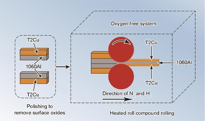
图1
Cu/1060Al/Cu三层复合材料高温无氧轧制工艺示意图
Fig.1
Schematic of Cu/1060Al/Cu three-layer composite prepared by high-temperature oxygen-free rolling process
1.2 微观组织表征
图2

图2
Cu/1060Al/Cu三层复合材料取样位置示意图和具体尺寸
Fig.2
Schematics of the sampling position (a) and sample dimensions (b-d) of Cu/1060Al/Cu three-layer composite (unit: mm. ND—normal direction, RD—rolling direction, TD—transverse direction, d—rolled sheet thickness)
(a) sampling position (b) metallographic sample (c) tensile sample (d) conductivity testing sample
1.3 力学性能测试
采用线切割方法从Cu/1060Al/Cu三层复合材料上截取试样标距 × 标距段宽度 × 厚度为15 mm × 3.5 mm × d mm的狗骨头状拉伸试片(图2c)。对拉伸试样侧边进行打磨,以消除线切割加工痕迹对拉伸结果的影响。利用Z100型电子万能试验机进行拉伸实验,拉伸速率为1 mm/min。
1.4 导电性能测试
1.4.1 电导率测试
采用线切割方法在待测试样板上截取尺寸为300 mm × 20 mm× d mm的试样用于电导率测试(图2d)。基于四点探针直流电法,采用ZCZR-10A型变压器直流电阻测试仪测量Cu/Al/Cu三层复合材料的电阻。将4个探针均匀地置于复合材料表面,其中外侧2个探针施加已知电流,内侧2个探针用于测量电压,每组测试重复5次并求平均值。得到Cu/1060Al/Cu三层复合材料的静态电阻后,计算出材料的电导率。
1.4.2 交流阻抗测试
采用线切割方法在不同Cu层厚度样板上截取尺寸为300 mm × 5 mm × d mm的试样用于交流阻抗测试。采用J61120BD型阻抗分析仪测量Cu/Al/Cu三层复合材料的交流阻抗。用导线夹连接试样长度方向两端和阻抗分析仪,施加0.1~100 kHz的电流频率,每组测试重复3次,得到Cu/1060Al/Cu三层复合材料的交流阻抗。
1.4.3 电流密度模拟
为了有效分析交流电流的趋肤效应在Cu/1060Al/Cu三层复合材料中作用的情况,采用Ansys中Maxwell2D/3D电磁场有限元分析软件对Cu/1060Al/Cu三层复合材料通交流电时的电流密度分布情况进行模拟计算。通过涡流场求解器分析趋肤效应的影响,求解的频率范围可以从零到数百兆赫兹,以云图或矢量图形式显示出整个相位的电流分布及能量密度等结果。
仿真模型(图3)建立的具体步骤为:(1) 在Maxwell3D软件中构建Cu/1060Al/Cu三层复合板的三维模型,选定材料(上下2层为T2Cu,中间层为1060Al;材料的长度为500 mm,宽度为5 mm,厚度为4 mm),因界面层厚度只有几微米,远小于Cu层和Al层的厚度,可忽略以简化模型;(2) 在复合板模型周围构建空气域,在复合板模型两端添加激励电压,并且确定电流流向为从左往右;(3) 对复合板进行网格划分,上/下Cu层和中间Al层都设置40000个网格进行划分,最后采用涡流场求解器,获得电流密度分布云图。
图3

图3
Cu/1060Al/Cu三层复合材料通电时电流密度分布情况模拟的仿真模型
Fig.3
Simulation model for calculating the current density distribution in Cu/1060Al/Cu three-layer composite during energization (unit: mm)
设置2种可变参数,分别为单侧Cu层厚度占比和电流频率。控制单侧Cu层厚度占比(10.0%、17.5%、25.0%)为变量,模拟不同电流频率(0.1、1、5、10、50、100 kHz)下,Cu/1060Al/Cu三层复合材料中电流密度的分布情况。
2 实验结果与讨论
2.1 Cu/1060Al/Cu三层复合材料微观组织
图4为轧制后Cu/1060Al/Cu复合材料界面的SEM像和EDS面分布图。由图可知,当轧制道次为1时,界面化合物连续分布,但由于轧制力的作用导致其界面厚度呈不均匀分布;当轧制道次为2时,随着轧制力的增加,界面化合物层破裂,形成大量窄缝,界面层不连续且存在微裂纹;当轧制道次为3时,随着轧制力进一步增加,窄缝演变为宽缝,界面化合物层两侧的Cu和Al结合在一起,形成冶金结合和机械啮合同时存在的情况。三层复合材料经过不同道次轧制后,界面层发生破裂,有助于内层的Cu/Al层结合。图5为经1和3道次轧制后Al/Al界面的OM像。相较于Cu/Al异种金属结合,Al/Al界面由于是同种金属结合,其晶格参数完全匹配,界面处无明显分界,因而具有优异的界面结合效果。
图4
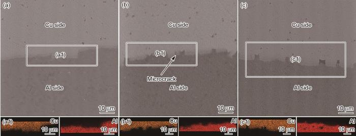
图4
轧制态Cu/1060Al/Cu三层复合材料界面的SEM像和EDS面分布图
Fig.4
SEM images (a-c) and corresponding EDS elemental mappings (a1-c1) of interfaces in Cu/1060Al/Cu three-layer composites with different rolling passes (a, a1) one pass (b, b1) two passes (c, c1) three passes
图5
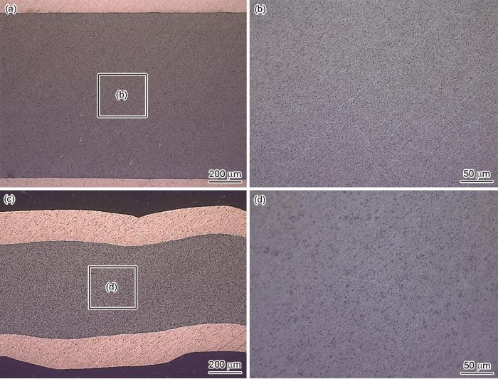
图5
Cu/1060Al/Cu三层复合材料经1和3道次轧制后Al/Al界面的OM像
Fig.5
Low (a, c) and high (b, d) magnified OM images of Al/Al bonding interfaces in Cu/1060Al/Cu three-layer composites with one pass (a, b) and three passes (c, d) rolling
图6为退火态Cu/1060Al双层复合材料和不同道次轧制后退火态Cu/1060Al/Cu三层复合材料界面的SEM像。如图6a所示,退火态Cu/1060Al双层复合材料界面化合物层均连续且均匀,其厚度为3.66 μm。如图6b~d所示,随着轧制道次的增加,Cu/Al界面层的厚度逐渐下降,1~3道次轧制后界面层厚度分别为4.56、4.43和4.39 μm。这是由于在轧制力的作用下,界面层在一定程度上被压薄。Cu/1060Al/Cu复合材料的Cu/Al界面层厚度相较于退火态Cu/1060Al双层复合材料略微上升。表2给出了不同道次轧制后Cu/1060Al/Cu三层复合材料界面层化合物的成分及种类。可见,从Cu侧到Al侧,不同道次轧制后Cu/Al界面层中的化合物均依次为Cu9Al4、CuAl及CuAl2。
图6
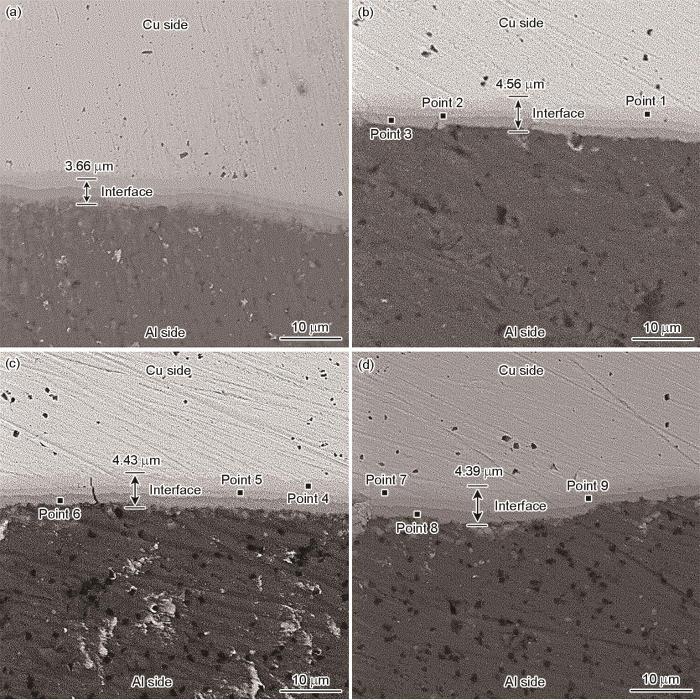
图6
退火态Cu/1060Al双层复合材料和不同道次轧制后退火态Cu/1060Al/Cu三层复合材料界面的SEM像
Fig.6
SEM images of interfaces in annealed Cu/1060Al two-layer composite (a) and annealed Cu/1060Al/Cu three-layer composites with different rolling passes (b-d)
(b) one pass (c) two passes (d) three passes
表2 不同道次轧制后Cu/1060Al/Cu三层复合材料界面层化合物的成分及种类 (atomic fraction / %)
Table 2
| Rolling pass | Point | Cu | Al | Phase |
|---|---|---|---|---|
| One pass | 1 | 71.39 | 28.61 | Cu9Al4 |
| 2 | 53.19 | 46.81 | CuAl | |
| 3 | 30.56 | 69.44 | CuAl2 | |
| Two passes | 4 | 69.85 | 30.15 | Cu9Al4 |
| 5 | 58.82 | 41.18 | CuAl | |
| 6 | 32.29 | 67.71 | CuAl2 | |
| Three passes | 7 | 71.68 | 28.32 | Cu9Al4 |
| 8 | 53.72 | 46.28 | CuAl | |
| 9 | 31.47 | 68.53 | CuAl2 |
2.2 Cu/1060Al/Cu三层复合材料力学性能
图7为不同道次轧制后退火前后Cu/1060Al/Cu三层复合材料的应力-应变曲线。如图7a所示,轧制态Cu/1060Al/Cu三层复合材料的应力-应变曲线不存在阶梯变化。因此,Cu/1060Al/Cu三层复合材料的断裂形式不是分层断裂,而是Cu层与Al层协同断裂。随着轧制道次的增加,层厚逐渐减小,三层复合材料的屈服强度和抗拉强度逐渐增加。在高温无氧轧制过程中,材料经历大量塑性变形而产生显著的形变强化,导致位错密度显著增加,界面层作为异质相界面,对位错传播路径产生干扰和阻断作用,产生位错堆积和应力集中,位错相互交织、缠结,给位错运动造成阻碍,从而提高了材料的强度,除此之外,高温无氧轧制条件促进了更多连续、致密的冶金结合区的形成,使得复合层间能够有效传递载荷。因此,Cu/Al/Cu复合材料在轧制过程中出现的高应变使得屈服强度和抗拉强度均得到显著提升[24]。依据强塑积(product of tensile strength and ductility,PTD)评估材料的综合性能。如表3所示,在保证强度的前提下,2道次轧制后材料的综合性能最优,屈服强度、抗拉强度和延伸率分别为94 MPa、161 MPa和58%。
图7

图7
不同道次轧制后退火前后Cu/1060Al/Cu三层复合材料的应力-应变曲线
Fig.7
Stress-strain curves of Cu/1060Al/Cu three-layer composites under different rolling passes without (a) and with (b) anneal treatment
表3 复合材料在不同工艺状态下的力学性能
Table 3
| Material | Process | YS MPa | UTS MPa | EL % | PTD MPa·% |
|---|---|---|---|---|---|
| Cu/Al two-layer composite | Two-pass rolling + annealing | 82 | 138 | 63 | 8694 |
Cu/1060Al/Cu three-layer composite | One-pass rolling | 86 | 155 | 50 | 7750 |
| Two-pass rolling | 94 | 161 | 58 | 9338 | |
| Three-pass rolling | 107 | 181 | 41 | 7421 | |
| One-pass rolling + annealing | 81 | 131 | 79 | 10349 | |
| Two-pass rolling + annealing | 107 | 178 | 67 | 11926 | |
| Three-pass rolling + annealing | 114 | 171 | 47 | 8037 |
图7b为不同道次轧制后退火态Cu/1060Al/Cu三层复合材料的应力-应变曲线。由图可知,退火态Cu/1060Al/Cu三层复合材料的屈服强度随着轧制道次的增加逐渐增加,而延伸率随着轧制道次的增加而下降。在保证强度的前提下,2道次轧制后退火态试样的强度与塑性匹配较好,屈服强度、抗拉强度和延伸率分别为107 MPa、178 MPa和67%,如表3所示。与轧制态试样的拉伸性能相比,退火态试样的延伸率均有所增加,但强度变化各异。其中,1道次和3道次轧制的退火态Cu/1060Al/Cu三层复合材料的抗拉强度下降,但2道次轧制后退火态Cu/1060Al/Cu三层复合材料的力学性能却有所提升。2和3道次轧制后退火态Cu/1060Al/Cu三层复合材料的强度均高于基体Cu/1060Al双层复合材料。在延伸率方面,经过3道次轧制并退火的三层复合材料的延伸率低于基体材料,而经过1和2道次轧制并退火的三层复合材料的延伸率则高于基体材料。整体而言,Cu/1060Al/Cu三层复合材料的综合性能优于Cu/1060Al双层复合材料。这是因为Al层两侧的Al/Cu界面层均能在拉伸过程中起到牵制Cu和Al层的作用,其牵制效果优于单侧复合Cu层。这种结构不仅使得Cu与Al层能够更好地协同变形,还进一步提高了复合材料的力学性能。
综上所述,轧制态和退火态Cu/1060Al/Cu三层复合材料的最优综合性能均在2道轧制次后获得,且其退火态的抗拉强度高于轧制态。这是因为轧制态界面层存在微裂纹,拉伸时裂纹更易萌生和扩展,从而降低材料的强度。尽管退火后Cu/Al材料发生软化[25],但界面层均匀且厚度合适,有利于抑制材料变形和断裂,此时界面层对材料性能的提升作用大于退火对材料的软化作用。此外,对于1和3道次试样,退火态抗拉强度较轧制态略有下降,且降幅较小;其中3道次试样退火态抗拉强度较轧制态仅降低10 MPa。同时,1和3道次试样退火态延伸率均较轧制态显著提升,这主要归因于退火态材料中均匀界面层所产生的强化效应。
研究[13]表明,在层状金属复合材料的拉伸过程中,软层内部滑移产生的位错往往在界面附近聚集,形成应力集中区。随着应变继续增加,界面应力集中可能引发微裂纹,并最终导致主裂纹在界面或相界面处萌生和扩展。Li等[26]关于Al/Cu层状复合材料的研究表明,拉伸过程中裂纹通常首先在界面层处萌生,并根据界面结合强度不同而异地扩展,界面结合强度高时裂纹扩展受到阻碍,而结合强度弱时易导致界面脱层。类似地,Chang等[27]研究表明,在拉伸过程中裂纹通常先在界面层产生,在界面限制作用达到极限后才扩展进入Cu层或Al层,最终造成试样断裂。在不同轧制道次下,Cu/1060Al/Cu三层复合材料的界面层未出现明显分层现象(图4),同时Cu层和Al层的厚度占比亦未发生显著变化。因此,不同道次轧制所得复合材料可视为组织致密、界面结合紧密的同类材料体系。轧制过程的主要作用在于促进界面冶金结合和组织致密化,并不改变其层状结构特征。Cu/Al复合材料在不同的变形量下,裂纹均优先在界面层产生,随后向两侧金属扩展并导致最终断裂[28,29]。由此可见,Cu/Al复合材料在不同变形量下表现出一致的断裂特征。
在轧制力作用下,轧制态Cu/1060Al/Cu三层复合材料从单一的机械结合转变为冶金结合与机械结合的复合结合方式,从而进一步提高了复合效果,且轧制力起到了形变强化的作用,材料的屈服强度和抗拉强度逐渐提高,而延伸率有所下降。轧制态Cu/1060Al/Cu三层复合材料的应力-应变曲线(图7a)未展现出如文献[23]所述的Cu/Al双层复合材料拉伸曲线所具有的阶梯状特征,这表明Cu层与Al层可实现较为良好的协同断裂行为,Cu/Al-Cu三层复合材料在断裂过程中未发生分层断裂。这一现象主要归因于高温轧制过程中Cu层与Al层界面生成了一定厚度的界面化合物层,该化合物层对Cu和Al层均产生了牵制作用,从而有效缓解了层状断裂的发生。在拉伸过程中,轧制态Cu/1060Al/Cu三层复合材料界面处容易形成位错塞积,导致应力集中。制备Cu/1060Al/Cu三层复合材料时,轧制力通常作用在界面层。一方面,界面层破裂有利于内层Cu/Al金属的复合;另一方面,界面层存在许多微裂纹,促使应力在界面层扩散,加速复合材料的断裂[12,13,26]。图8为轧制态Cu/1060Al/Cu三层复合材料拉伸断裂机理示意图。材料的断裂过程如下:位错从基体材料扩散至界面层两侧,在界面层两侧形成位错塞积和应力集中;应力通过界面层中的微裂纹加速扩散,导致微裂纹长大,形成裂纹;裂纹快速扩展到Cu层和Al层,Cu/1060Al/Cu三层复合材料发生协同断裂。
图8

图8
轧制态Cu/1060Al/Cu三层复合材料拉伸断裂机理示意图
Fig.8
Schematics of tensile fracture mechanism of rolled Cu/1060Al/Cu three-layer composite (IMCs—intermetallic compounds)
(a) initial state (b) dislocation plugging in microcracks
(c) microcrack growth (d) crack propagation and fracture
对轧制态Cu/1060Al/Cu三层复合材料进行350 ℃、2 h退火处理,可消除加工应力,从而使基体晶粒长大,材料强度降低,塑性提高。退火后,界面层中微裂纹得以消除,这在一定程度上提高了材料的力学性能。因此,尽管退火后材料整体强度略有降低,但经过2道次轧制后,材料的强度却略微提升。退火后的轧制态Cu/1060Al/Cu三层复合材料界面化合物层的组成与Cu/1060Al双层复合材料相同(均为Cu9Al4、CuAl、CuAl2),并且具有相近的厚度(4.4 μm左右)。在拉伸过程中,随着载荷增加,Cu层和Al层都发生塑性变形,产生大量位错,位错运动至界面层,产生严重的位错塞积。由于界面化合物层在承受塑性变形的同时也承担较高的应力,当拉伸应力逐步接近界面化合物层的临界承载能力时,新的裂纹开始在界面化合物层内部萌生。随着拉伸载荷的进一步增加,这些裂纹沿界面化合物层扩展,并迅速扩展到Cu和Al层,导致Cu层和Al层发生协同断裂[12,13,30~32]。图9为退火态Cu/1060Al/Cu三层复合材料拉伸断裂机理示意图。经过退火处理后,Cu/1060Al/Cu三层复合材料界面层中的原始微裂纹被完全消除,界面层更加均匀和完整;在拉伸载荷的作用下,位错从基体材料传播到界面层两侧,界面层两侧形成位错塞积和应力集中;随着拉伸载荷的增加,当应力超过界面化合物层的承载极限时,新裂纹开始在界面层中萌生并沿界面层扩展;裂纹迅速扩展到Cu和Al层,Cu/1060Al/Cu三层复合材料发生协同断裂。
图9

图9
退火态Cu/1060Al/Cu三层复合材料拉伸断裂机理示意图
Fig.9
Schematics of tensile fracture mechanism of annealed Cu/1060Al/Cu three-layer composite
(a) initial state (b) dislocation plugging
(c) cracks initiation in IMCs (d) crack propagation and fracture
2.3 Cu/1060Al/Cu三层复合材料导电性能
2.3.1 Cu/1060Al/Cu三层复合材料电导率测试
电导率是Cu/Al/Cu三层复合材料的重要导电性能指标之一。电导率决定着Cu/1060Al/Cu复合材料作为导体使用的可能性和应用范围。本工作系统地测试了1~3道次轧制后退火态Cu/1060Al/Cu三层复合材料(轧板厚度分别为4、2和1 mm,单侧Cu层厚度占比为17.5%)的导电性能。测得电阻(R)后,通过如下公式计算电阻率(ρ):
式中,l为测试长度,S为横截面积。
根据
在不考虑中间化合层影响的情况下,平行于界面方向上的层状复合材料总电阻率的理论计算公式为:
式中,VAl和VCu分别为Al和Cu的体积分数,ρAl和ρCu分别为Al和Cu的电阻率。结合
表4为不同道次轧制后退火态Cu/1060Al/Cu三层复合材料的直流电阻测试参数和结果。随着材料厚度的增加,电阻率略微下降,电导率略微上升。退火态Cu/1060Al/Cu三层复合材料在1~3道次轧制后的电导率分别为74.0、73.0和70.1%IACS。不同道次轧制后,退火态Cu/1060Al/Cu三层复合材料电导率的变化主要与晶粒细化、晶界增多和位错密度的变化有关。随着轧制道次增加(即轧板厚度减小),材料在轧制过程中经历更大的塑性变形,导致晶粒尺寸逐渐减小。晶粒的细化增加了材料的晶界数量,而晶界作为电子的散射源,阻碍电子的流动,从而降低电导率。与此同时,轧制道次较多的轧板通常伴随着更多位错的形成,位错的增加进一步加剧电子散射,降低导电性。虽然退火处理可以减轻内应力和减少部分位错,但由于晶粒尺寸的减小和晶界的增多,这些因素仍然对电导率产生较大影响[33]。
表4 不同道次轧制后退火态Cu/1060Al/Cu三层复合材料的直流电阻测试参数和结果
Table 4
| Rolling pass | d mm | Length mm | Cross-sectional area mm2 | Resistance μΩ | Resistivity μΩ·mm | Conductivity | |
|---|---|---|---|---|---|---|---|
| MS·m-1 | %IACS | ||||||
| One pass | 4 | 250 | 78.95 | 60.1 ± 0.1 | 0.0236 | 42.2 | 74.0 |
| Two passes | 2 | 250 | 40.66 | 147.8 ± 0.2 | 0.0240 | 41.6 | 73.0 |
| Three passes | 1 | 250 | 18.35 | 340.6 ± 0.4 | 0.0250 | 40.0 | 70.1 |
2.3.2 Cu/1060Al/Cu三层复合材料Ansys电流密度分布情况模拟
为探索Cu层占比对Cu/1060Al/Cu三层复合材料中交变电流分布特性的影响,设置了3种不同的单侧Cu层占比(分别为10.0%、17.5%和25.0%),模拟结果如图10~12所示。复合材料整体厚度为4 mm,宽度为5 mm,两端施加220 V电压。仿真结果表明,三种厚度的复合材料在不同频率下电流密度均呈现出由均匀分布向表面集中的演变趋势,电流密度分布形态与频率密切相关。电流频率为0.1 kHz时,Cu层和Al层的电流密度分布均具有一致性,导体中电流密度的分布较为均匀。随着频率的提高,电流密度分布发生显著改变,电流频率为1 kHz时,边缘区域电流密度逐渐增强,各试样中电流密度呈现出近似椭圆形的分布;电流频率为10 kHz时,趋肤效应显著增强,电流高度集中于导体表层,内部区域电流大幅衰减,各试样中电流密度分布呈现出较为对称的矩形形态;电流频率进一步升至50和100 kHz后,电流基本完全集中在材料的最外层表面,导体内部形成大面积低电流密度区。电流分布边缘呈现出波动性,外层电流密度明显高于内层电流密度,从Cu层到Al层,电流分布存在不连续性的现象。Cu层的电流密度显著高于Al层,显示出两层之间的电流传输特性差异。随着Cu层占比的增加,高频电流分布越集中于高导电区域,有效提升了导体整体的载流能力。上述结果表明,电流密度分布的形态主要受电流频率的影响,而整体电流密度大小受Cu层厚度占比和电流频率的共同影响。
图10

图10
单侧Cu层厚度占比为10.0%时Cu/1060Al/Cu三层复合材料在220 V交流电下的电流密度分布
Fig.10
Current density (J) distributions of Cu/1060Al/Cu three-layer composites with 10% single-side Cu layer thickness ratio under 220 V alternating current (AC) and different current frequencies
(a) 0.1 kHz (b) 1 kHz (c) 5 kHz (d) 10 kHz (e) 50 kHz (f) 100 kHz
图11
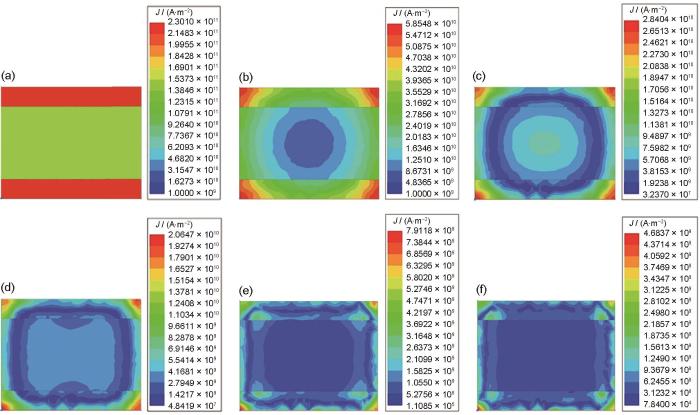
图11
单侧Cu层厚度占比为17.5%时Cu/1060Al/Cu三层复合材料在220 V交流电下的电流密度分布
Fig.11
Current density distributions of Cu/1060Al/Cu three-layer composites with 17.5% single-side Cu layer thickness ratio under 220 V AC and different current frequencies
(a) 0.1 kHz (b) 1 kHz (c) 5 kHz (d) 10 kHz (e) 50 kHz (f) 100 kHz
图12

图12
单侧Cu层厚度占比为25.0%时Cu/1060Al/Cu三层复合材料在220 V交流电下的电流密度分布
Fig.12
Current density distributions of Cu/1060Al/Cu three-layer composites with 22.5% single-side Cu layer thickness ratio under 220 V AC and different current frequencies
(a) 0.1 kHz (b) 1 kHz (c) 5 kHz (d) 10 kHz (e) 50 kHz (f) 100 kHz
从整体电流密度来看,在相同Cu层厚度占比下,随着电流频率的增加,导体中平均电流密度呈逐渐减小的趋势。这一现象主要归因于趋肤效应的增强,趋肤深度(δ)可由以下公式计算得出:
式中,ω为角频率(ω = 2πf),f为电流频率,μ为磁导率[34,35]。由
图13

图13
不同单侧Cu层厚度占比下Cu/Al/Cu三层复合材料交流阻抗测试结果
Fig.13
AC impedance test results of Cu/Al/Cu three-layer composites with different Cu layer thickness ratios
3 结论
(1) 通过高温无氧轧制工艺制备了Cu/1060Al/Cu三层复合材料。随着轧制道次增加,内层Cu/Al层在轧制力的作用下,形成了冶金结合和机械结合的复合结合方式,增强了复合效果。此外,Cu/Al界面层产生微裂纹,加速了拉伸过程中复合材料断裂进程,导致其力学性能下降。
(2) 经350 ℃、2 h退火处理后,Cu/1060Al/Cu三层复合材料的界面层展现出均匀和连续性,轧制态试样中的微裂纹消失,界面结合质量得到显著提升。在2道次轧制和退火条件下,复合材料的综合力学性能最佳,屈服强度、抗拉强度和延伸率分别为107 MPa、178 MPa和67%。在此条件下,复合材料的拉伸断裂模式表现为协同断裂,界面耦合作用及两侧Cu层对Al层的牵制作用是主要的影响因素。
(3) 1~3道次轧制后退火态Cu/1060Al/Cu三层复合材料的电导率分别为74.0、73.0和70.1%IACS,尽管略低于理论电导率76.0%IACS,但已满足作为导体材料的电导率要求。
(4) 退火态Cu/1060Al/Cu三层复合材料的交变电流密度分布遵循交变电流的趋肤效应特征,受到电流频率和Cu层厚度占比的共同影响。平均电流密度随着Cu层占比增加而逐渐上升,随电流频率增加而下降。在设计Cu/Al层状复合材料的Cu层占比时,综合考虑导电性和材料成本,单侧Cu层占比10.0%~17.5%是较优设计区间。
参考文献
Study on microstructure and properties of ultra-thin Cu/Al composite sheets using the cold-rolled composite method at the microscale
[J].
In this paper, an ultra-thin Cu/Al composite sheet with a thickness of 0.08 mm was obtained via the cold-rolling composite method using a four-high micro-rolling mill in the laboratory. The rolling reduction of a single pass was 65%. After the annealing of the ultra-thin Cu/Al composite sheets at temperatures ranging from 350 °C to 500 °C, the interface bonding mode of the Cu/Al composite sheets changed from mechanical bonding to metallurgical bonding, and the bonding strength was significantly improved. The microhardness value at the bonding interface of the ultra-thin Cu/Al composite sheets increases with the increase in annealing temperature. When the annealing temperature is 500 °C, the maximum microhardness value at the bonding interface reached 2.0 GPa. With the increase in annealing temperature, the tensile strength and elongation of the ultra-thin Cu/Al composite sheets decreases significantly. The peel strength of the extremely thin Cu/Al composite sheets increases at first and then decreases with the increase in annealing temperature, and reached the maximum value at an annealing temperature of 400 °C. When the annealing temperature was 400 °C, the tensile and peel properties of the ultra-thin Cu/Al composite sheet reached the best state.
Microstructural evolution and mechanical properties of laminated Cu/Al composites processed by accumulative roll-bonding and annealing
[J].
Cast-rolling force model in solid-liquid cast-rolling bonding (SLCRB) process for fabricating bimetal clad strips
[J].
Numerical simulation analysis of continuous casting cladding forming for Cu-Al composites
[J].High performance Cu-Al composites have widely applied in aviation, aerospace and other fields, at the same time the continuous casting as one of composite forming technologies has been also developed in recent years. Obviously, it is an effective and cheap way to numerically simulate the solidification process of short process continuous casting for manufacturing Cu-Al composites before fabricating them. To meet the need of simulation, in this work, a numerical method for theoretically describing the Cu-Al composite forming in continuous casting processes was proposed. The vertical continuous casting of copper clad aluminum bar billet and the horizontal continuous casting of copper and aluminum composite plate were performed. Based on this method, the steady state temperature fields in solidification processes in the above two kinds of casting technologies were numerically simulated by using proCAST software package. In this work the effects of the theoretical parameters on the steady state temperature fields and then on the performance of Cu-Al composites fabricated by using the above two casting technologies were carefully discussed. It is found that the experimental and simulated results are in good agreement. For the cases of the copper clad aluminum bar billet with a cross section of 100 mm×100 mm, and the copper or aluminum plate with a thickness of 20 mm and a width of 75 mm (coat thicknesses of 4~7 mm), the feasible parameters for producing high performance Cu-Al composites, for examples, are as follows: for the former the temperature of copper liquid is 1250 ℃, the temperature of aluminum liquid is 750 ℃, the length of crystallizer is 200 mm, the length of graphite mandrel tube is 290 mm, the flux of the first cooling water is 1600~2000 L/h, the flux of the second cooling water is 900~1300 L/h, the distance from the second cooling water to the exit of crystallizer is 30 mm, and the withdrawing speed is 60~80 mm/min. For the latter the temperature of copper melt was 1250 ℃, the temperatures of aluminum melt are 760~800 ℃, the withdrawing speed is 40~80 mm/min, and the length of aluminum duct is 20 mm.
Cu/Al复合材料连铸直接成形数值模拟研究
[J].建立了Cu-Al复合材料连铸成形的数值模拟模型,确定了模型的边界条件,提出了复合过程处理和结果评价方法。通过与部分实验结果对比表明,模拟结果与实验结果一致。以铜包铝棒坯立式连铸和Cu-Al复合板坯水平连铸过程为例,采用ProCAST软件对其稳态温度场进行了数值模拟分析,得到了各工艺参数对连铸过程的影响规律,给出了合理的工艺参数范围,并结合模拟的参数进行相应的实验研究。结果表明,本工作建立的连铸复合模型、确定的边界条件、提出的复合过程处理和结果评价方法合理,可有效用于连铸复合成形模拟分析。计算结果表明,制备横断面为100 mm×100 mm、Cu包覆层厚度(4~10 mm)的铜包铝棒坯可行的连铸工艺参数为:Cu液温度1250 ℃,Al液温度750 ℃,结晶器长度200 mm,芯棒管长度290 mm,一冷水流量1600~2000 L/h,二冷水流量900~1300 L/h,二冷水距结晶器出口距离30 mm,拉坯速率60~80 mm/min;制备厚度20 mm、宽度75 mm、Cu包覆层厚度(4~7 mm)的Cu-Al复合板坯可行的工艺参数为:Cu液温度1250 ℃,Al液温度760~800 ℃,拉坯速率40~80 mm/min,Al液导流管长度20 mm。
Mechanism of warm and cold roll bonding of aluminum alloy strips
[J].
Study of mechanisms of cold roll welding of aluminium alloy to steel strip
[J].
Interfacial microstructure and mechanical properties of Cu/Al clad sheet fabricated by asymmetrical roll bonding and annealing
[J].
Bond strength evaluation of roll bonded bi-layer copper alloy strips in different rolling conditions
[J].
Enhanced mechanical properties of lamellar Cu/Al composites processed via high-temperature accumulative roll bonding
[J].
Effect of interfacial bonding strength on tensile ductility of multilayered steel composites
[J].
Role of layered structure in ductility improvement of layered Ti-Al metal composite
[J].
Evaluation of interface structure and high-temperature tensile behavior in Cu/Al8011/Al5052 trilayered composite
[J].
Characteristic investigation of trilayered Cu/Al8011/Al1060 composite: interface morphology, microstructure, and in-situ tensile deformation
[J].
Study on the electric conduction properties of copper and aluminum cladding plate with size changing
[A].
铜铝复合板尺寸对导电性能的影响
[A].
Study on the thermoelectric properties of copper/aluminum composite
[J].Using a new type of induction heating process, copper/aluminum composite was prepared by solid-liquid-solid method. The resistivity of binding layers of different components and the relationship between the thickness of bonding layers and the thermoelectric properties of copper/aluminum composite were investigated. The thermal conductivity was observed by xenon lamp thermal conductivity meter DXF200. The resistivity was measured by SB100A/20A four probe conductor/semiconductor resistivity tester. The results showed that the thermal conductivity of Cu/Al compound materials bonding layers is 205.6 W/(m·K) and the resistivities of Intermetallic compounds of bonding layer,Cu<sub>9</sub>Al<sub>4</sub> layer, AlCu layer and CuAl<sub>2</sub> layer are 14.35×10<sup>-8</sup>, 8.17×10<sup>-8</sup> and 11.56×10<sup>-8</sup> Ω·m, respectively. Moreover, with the concentration of the thickness of bonding layers, the complex thermal conductivity of copper/aluminum composite gradually decreased. When the thickness of bonding layer was in the range of 1 to 100 μm, the copper/aluminum composite produced the satisfactory thermoelectric properties.
Cu/Al复合材料热电性能的研究
[J].运用新型感应加热工艺,通过固-液-固相复合法制备铜/铝复合材料。分析了不同成分结合层的电阻率及结合层厚度与铜铝复合材料热电性能间的关系。实验中用氙灯导热仪DXF200对Cu/Al复合材料结合层的导热系数进行测定,用SB100A/20A型四探针导体/半导体电阻率测试仪对Cu/Al复合材料结合层电阻率进行测定。结果表明,铜铝复合材料结合层的导热系数为205.6 W/(m·K),铜铝复合材料中间化合物Cu<sub>9</sub>Al<sub>4</sub>的电阻率为14.35×10<sup>-8</sup> Ω·m,CuAl的电阻率为11.56×10<sup>-8</sup> Ω·m,CuAl<sub>2</sub>的电阻率为8.17×10<sup>-8</sup> Ω·m,且随着结合层厚度的增加,复合材料的等效导热系数逐渐减小,当铜铝复合材料结合层厚度保持在1~100 μm的范围时有具有较好的导电、导热性能。
Effects of running conditions on the conductivity of copper cladding aluminum flat bars
[J].
工作条件对铜包铝扁排导电性能的影响
[J].
The microstructure and property variations of metals induced by electric current treatment: A review
[J].
Simulation of the electric characteristics of Cu-Al-Cu cladding plate
[J].
铜-铝-铜复合板导电特性的模拟
[J].
Effect of service condition on copper aluminum composite electrical performance
[J].
服役条件对铜铝冷轧复合导电排性能的影响
[J].
Gradient alternating deformation mechanism of two metals and interface bonding mechanism of Cu/Al cold rolling composite process
[J].
Bonding behavior during cold roll-cladding of tri-layered Al/brass/Al composite
[J].
Interface evolution during rolling of Ni-clad stainless steel plate
[J].Plate of Ni-clad 316H stainless steel was prepared via hot rolling process after pre-heating at 1200oC for 120 minutes, then concurrently the rolling process was interrupted after rolling for 3, 5, and 7 passes respectively, while the relevant samples are taken and water-quenched for subsequent characterization in terms of the evolution of their interface-composition and -morphology, as well as the formed oxides there. Results show that until the 3rd rolling pass, the rolling plate temperature was about 1000°C, the two metals were closely bounded with equiaxed grains of slightly distorted microstructure on both sides of the interface and the inter-diffusion of elements for the two metals was not obvious; Until the 5th rolling pass, the plate temperature was about 940°C, the grains of 316H were elongated with significant lattice distortion, whereas, obvious inter-diffusion can be found near the interface; Until the 7th rolling pass, the plate temperature was about 880°C, large number of elongated and distorted grains were observed on the 316H steel side and a fine grain structure crushed by hot rolling distributed near the interface. The elements of Ni, Fe and Cr were fully inter-diffused near the interface, but the less motionable Mo enriched at the 316H side. The grains of Ni layer coarsened obviously. The interface evolution of Ni/stainless steel composite plate during the rolling process follows the so called three-stage theory and N. Bay's theory. The physical contact stage and the physical-chemical contact stage happened between the 3rd and 5th pass. Then the rolling from 5th to 7th pass was the final physical-chemical contact phase, whilst the inter-diffusion begins, that is, the "bulk" mutual phase begins. In the high-temperature and low-oxygen environment, the Mn oxides near the interface might form during the rolling process. The oxide was crushed and squeezed toward the substrate by the rolling force, therefore distributed in chains near the interface eventually.
镍-不锈钢复合板轧制过程中界面的结合机制
[J].采用轧制终止取样法对镍-不锈钢热轧复合板轧制过程中的界面成分、界面组织以及界面处的氧化物进行了表征,研究了轧制过程中界面的结合机制并根据热力学原理解释了高温下选择性内氧化的机理。将复合板坯加热至1200℃,保温120 min后进行轧制,分别在轧制3、5、7道次后中断轧制快速水冷,随后进行取样观察。结果表明,轧制3道次时终轧温度为1000℃左右,金属之间有近距离结合,微观组织有轻微的畸变,界面两侧的板材均为等轴晶粒,元素的扩散不甚明显;轧制至5道次时终轧温度为940℃左右,316H的晶粒被拉长而发生晶格畸变,界面附近出现明显的扩散行为;轧制到7道次时终轧温度为880℃,316H层出现大量拉长的畸变晶粒,界面处主要是轧碎的细晶组织,但Ni层的晶粒粗大,界面附近Ni、Fe和Cr元素充分扩散,微弱扩散的Mo元素在316H界面富集。镍-不锈钢复合板在轧制过程中界面的演化遵循三阶段理论和N.Bay理论,3道次到5道次间处于物理接触阶段、物理化学阶段,轧制7道次时物理化学阶段结束并开始扩散,即开始进入“体”相互阶段,主要元素在此阶段完成相互扩散。在高温低氧环境的轧制条件下,界面处生成Mn的氧化物,该氧化物因轧制而破碎并向基材挤压最终在界面附近成链状分布。
Microstructure and mechanical properties of high-temperature free-oxygen rolled Cu/1060Al bimetallic composite materials
[J].
Interface-dominated microstructure development and mechanical and electrical properties of Al/Cu multilayered composites prepared via multicomponent accumulative roll bonding
[J].
Influence of softening annealing on microstructural heredity and mechanical properties of medium-Mn steel
[J].Softening annealing (SA) is often required for producing medium-Mn steels (MMS) as it lowers hardness so that they can be cold rolled to reduce thickness. The influences of different SA processes on the microstructural heredity during the processing route and the final tensile properties were studied. It was found that the SA process could either intensify or weaken the influence of the Mn segregation resulting from solidification on the subsequent microstructural evolution during the process, i.e., microstructural heredity. In the case when no SA was employed, both recrystallization and rapid growth of ferrite grains preceded the reverse austenitic transformation during the intercritical annealing (IA) in the Mn-lean regions, where very coarse ferrite grains were formed. This deteriorated ductility due to the propagation of cracking along the boundary of the coarse-grained and fine-grained regions. In contrast, SA at a sufficiently high temperature could dissolve cementite, producing uniformly distributed austenite grains. They transformed to martensite during cold rolling but were reborn during IA. As a result, ultrafine austenite and ferrite grains were uniformly distributed, which improved ductility significantly. This study hints at a new approach to altering the microstructural heredity resulting from the heterogeneous Mn distribution in MMS.
Deformation behavior and crack propagation on interface of Al/Cu laminated composites in uniaxial tensile test
[J].The microstructural characterization and uniaxial tensile tests of Al/Cu laminated composites were taken to investigate the interface effect and fracture process of the composites. The electron microscopic graphs before and after tensile test were used to evaluate the fracture behavior. Experimental results show that the fracture surfaces of laminated composites mainly present brittle failure characteristics, accompanied with several dimples on the matrixes and a few tearing on the interface. Cracks generally initiate from the interfacial interlayer and variously propagate depending on the interfacial bonding. It is found that Cu/Al interface with enhanced bonding strength generally hinders the propagation of interlayer cracks, while the interface with weak bonding delaminates by the cracks propagation through the interfacial defects. The additional shear stress on the interface between Cu and Al layers due to their different tensile ductilities aggravates the interfacial propagation of cracks. The local plastic deformation of individual matrix layer then occurs after cracks coalesce and failure in the interface. Therefore, the strong bonding interface and matching properties between individual matrix layers are required to improve the fracture performance of Al/Cu laminated composites.
Effects of asymmetry and annealing on interfacial microstructure and mechanical properties of Cu/Al laminated composite fabricated by asymmetrical roll bonding
[J].
Study on interface behavior and mechanical properties of Al/Cu laminated tubes fabricated by strong staggered spinning at room temperature
[J].
Study on microstructure evolution and fracture behavior of Al/Al/Cu multilayer composites
[J].
Tailoring of interface structure and mechanical properties in ARBed 1100/7075 laminated composites by cold rolling
[J].
Microstructure and mechanical behaviors of Al/Cu laminated composites fabricated by accumulative roll bonding and intermediate annealing
[J].
A novel approach for preparing Cu/Al laminated composite based on corrugated roll
[J].In this paper, Cu/Al laminated composite was prepared by a novel approach, corrugated + flat rolling (CFR) method, with low reduction ratio of 20% per pass, and the microstructure and mechanical properties were investigated. The results indicate that the preliminary combination of the composite can be realized by the first CFR pass and the composite with complete combination was obtained after the flattening rolling process. The corrugated bonding interface was formed without intermetallic phase, and the grain refinement (especially at the interface) occurred after the CFR process. Furthermore, the Cu/Al laminated composite with corrugated bonding interface exhibits outstanding tension-shear and tensile properties. (C) 2018 Elsevier B.V.
Mechanical and electrical properties of Al/18Cu/3WC/3MoS2 multilayered hybrid composites fabricated by accumulative roll bonding
[J].
Numerical simulation on the forming process of Cu/A1 composite tube and distribution of current across the section
[D].
铜铝复合管成形数值模拟及电流通过截面分布规律
[D].
The study on the electrical properties and the cold rolling technique for copper and aluminum composite laminates
[D].
铜铝轧制复合板导电特性及复合技术的研究
[D].
