


在金属凝固过程中,由于固/液相相对运动的存在,使熔体凝固过程中易出现宏观尺度的溶质分布不均匀,即宏观偏析。而不同金属材料在焊接、熔覆等加工工艺下极易出现偏析带,偏析带的出现直接影响凝固裂纹控制、耐腐蚀性能,乃至最终产品质量。因此,国内外学者对此开展了广泛的实验研究。如Chen等[1]研究了316L不锈钢/IN625合金在定向能量沉积过程中合金成分对界面形貌的影响,结果表明,在IN625合金上沉积316L不锈钢形成的界面处具有成分突变区,这是由于IN625合金具有高密度和高黏度,阻碍了成分的充分混合。此外,在界面处及其附近存在裂纹,这是由重熔的IN625未混合区域引起Nb和Mo元素的微观偏析,从而导致液化开裂。Barr等[2]研究了3种超高强度钢的合金成分对熔覆质量的影响,结果表明,由熔覆层与基体成分差异引起的熔化温度差异是宏观偏析形成的主要原因,而宏观偏析的出现最终导致熔覆层开裂,并提出了通过延长熔覆过程中的激光作用时间来控制偏析带和裂纹的方法。Soysal等[3]根据焊缝金属与基板液相线温度不同的特点,提出了宏观偏析形成及演化机制,并在纯Cu薄板与低碳钢薄板对接焊中验证了该机制,形成了未混合钢的“半岛(peninsula)”形貌和未混合Cu的不规则形状的“海滩(beach)”。Liu等[4]采用激光熔覆技术在300M钢表面制备了Aer Met100钢涂层,涂层在熔体对流不充分的情况下会发生宏观偏析,严重的宏观偏析会降低熔覆层的耐腐蚀性能,结果表明,提高激光功率和降低扫描速率可减小偏析程度。由于异种金属冶金结合过程现象复杂并且难以直接观察,目前实验研究主要通过结果来推测偏析带形成的原因,这导致熔池形貌和熔池流动等因素对偏析带形成的影响尚不清晰。
随着计算机技术的快速发展,许多学者运用数值模拟的方式来研究溶质元素的分布情况,Gan等[5]建立了在铸铁上沉积镍基合金的三维数值模型,发现成分运输和凝固行为显著影响熔覆层的组织和性能,并在熔覆层的底部发现了元素分布不均匀的现象。Ge等[6]利用Eulerian多相流算法建立了在45钢上熔覆316L不锈钢的二维三相数值模型,发现熔池前端的预混合阶段和熔池后端的充分混合阶段对熔覆层中成分的最终分布有显著影响,并观察到熔覆层中Cr元素分布不均匀的现象。Li等[7]研究了Ni和304不锈钢激光线性异种焊接过程中的热行为和流体流动,结果表明,熔池中的对流是主要的传质机制,由于熔池顶部流体的强烈流动,元素主要在顶部区域混合,然后通过三维涡流向熔池底部运输,使得元素分布的传输较为均匀。Wolff等[8]建立了在1045碳钢上熔覆IN718合金的三维数值模型,该模型处理了熔池中粉末与基板材料之间成分混合引起的热物理性质变化,结果表明,显微硬度的变化主要由粉末与基体材料之间的成分混合决定。截至目前,大部分模拟研究均发现异种金属激光焊接或者熔覆过程中结合区域易出现成分不均匀现象,但是与实验结果相比,模拟结果中均未出现明显的偏析带,且少有模型实现组织和偏析的同步预测。
本工作将元胞自动机方法和Eulerian多相流算法相结合,建立异种材料激光粉末床熔覆熔化/凝固模型,系统研究异种金属材料在冶金结合过程中偏析带的形成及演化机制,为加工工程中偏析带形成及控制提供理论支撑。
1 传热与传质模型的建立及求解
1.1 数值模型
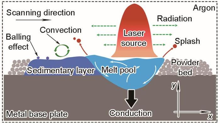
图1为铺粉式激光熔覆工艺示意图。在316L不锈钢基板上预置一层IN718金属粉末,通过高能量密度的激光束加热熔覆合金粉末,使粉末与基板表面快速熔化,随着激光束向前移动,熔池凝固形成一层具有特定用途的熔覆涂层。
图1
为在保证计算精度的前提下提高求解效率,本模型主要假设如下:(1) 模型中只考虑固相和液相,且两相体积分数之和fs + fl = 1;(2) 激光光源作用在熔池表面,且能量呈Gaussian分布;(3) 熔融流体在熔池中为不可压缩、层流的Newton流体;(4) 粉末为连续的固相,熔化后再凝固;(5) 忽略蒸汽和反压力的作用;(6) 不考虑凝固收缩;(7) 晶粒无运动;(8) 不考虑元素间的相互作用和再分配;(9) 由于实验中IN718粉末层较少,熔覆涂层稀释率较高,IN718合金的影响相对较小,模型中的热物性参数主要参考316L不锈钢,液相线温度主要根据2种材料中的元素含量计算获得。本工作只考虑Fe、Cr和Ni 3种主要元素,将多元合金简化为等效的Fe-X (X = Ni、Cr)二元系。等效初始质量分数(
式中,下标i表示第i个二元系中的物理性质,N为合金中的元素个数,c0为初始元素的质量分数,k为溶质元素的分配系数,m为溶质元素的液相线斜率,D为溶质元素的扩散系数。
式中, Vn为固/液界面的法向生长速度,m/s;
式中,Vx 为液/固界面在x方向上的生长速率,m/s;Δx为网格尺寸;
式中,
1.1.1 基本控制方程
质量守恒方程表达式为:
式中,ρl和ρs分别为液相和固相密度; ul为熔体的流速;t为时间;Mls为液相向固相的传输质量,其表达式为Mls = Δfs·ρ / Δt。
动量守恒方程为:
式中,p为压力; τ1为应力-应变张量; Uls为液相与固相动量交换量; FM为引起Marangoni流的动量源项,表达式为
能量守恒方程为:
式中,hl和hs分别为液相和固相的焓;kql和kqs分别为液相和固相的热导率;Tl和Ts分别为液相和固相的温度;Qls为液相和固相间的能量交换项;Qql和Qqs分别为液相和固相吸收的激光能量,激光热源以源项的方式植入能量方程。
Gaussian热源通量(q(r))表达式为:
式中,A为激光利用率,P为激光功率,R为激光光斑半径,r为距离斑点中心的距离。
溶质守恒方程为:
式中,Cls为液相与固相之间的溶质传输量,凝固时
1.1.2 形核模型
式中,ΔTn和ΔTσ 分别为形核过冷度的均值和标准偏差,K;nmax为最大形核率。因此,对于任意过冷度的晶粒密度(n(ΔT))可由以下公式求得:
在一个时间步长内,过冷度增量为δ(ΔT),则一个时间步长内的晶粒密度增量(δn)可表示为:
因此当前元胞的形核概率为Pn = δn·Vc,Vc为元胞的体积。当该元胞的形核概率大于一个(0, 1)的随机数时,该元胞发生形核,由液相胞转变成界面胞,并在(-0.25π, 0.25π)内赋予其随机生长方向。
1.2 数值求解
本模型采用2D正方形网格,图2所示为计算域网格及边界条件,其中流体域尺寸为14 mm × 1.2 mm,网格尺寸为10 μm × 10 μm,其余网格从上到下依次增大,粉末层简化为固相,高度设置与实验结果一致。模型边界为壁面,初始温度为室温300 K,初始溶质质量分数根据
图2
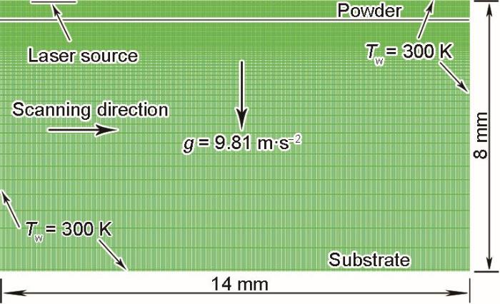
图2
计算域的边界条件和网格
Fig.2
Characteristics of boundary conditions and grids in the computational domain (g—acceleration of gravity; Tw—wall boundary condition)
| Parameter | Symbol | Value | Unit |
|---|---|---|---|
| Melting point of pure Fe | Tf | 1805.15 | K |
| Reference densities of liquid and solid | ρl, ρs | 8000 | kg·m-3 |
| Specific heat | cp | 500 | J·kg-1·K-1 |
| Thermal conductivity of solid | kqs | 19.2 | W·m-1·K-1 |
| Thermal conductivity of liquid | kql | 209.2 | W·m-1·K-1 |
| Latent heat | Δhf | 250000 | J·kg-1 |
| Viscosity | μl | 0.0042 | kg·m-1·s-1 |
| Volume heat-transfer coefficient | H* | 1 × 10⁹ | W·m-2·K-1 |
| Temperature coefficient of surface tension | ∂γ / ∂T | -4.3 × 10⁻⁴ | N·m-1·K-1 |
| Maximum nucleation density | nmax | 1 × 10⁹ | m-3 |
| Average nucleation undercooling | ΔTn | 15 | K |
| Nucleation undercooling deviation | ΔTσ | 5 | K |
2 实验设计
2.1 实验设备及材料
图3
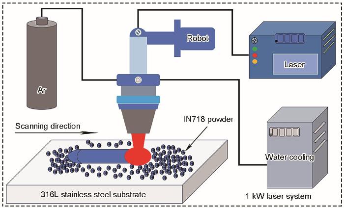
图3
激光粉末床熔覆工作平台示意图
Fig.3
Schematic description of work platform for laser powder bed cladding
表2 316L基板和IN718粉末的化学成分 (mass fraction / %)
Table 2
| Material | Fe | Ni | Mn | Al | Ti | Nb | Si | Cr | Mo | C |
|---|---|---|---|---|---|---|---|---|---|---|
| 316L | Bal. | 10.0 | 1.55 | - | - | - | 0.55 | 16.5 | 2.08 | 0.020 |
| IN718 | 18.1 | Bal. | 0.04 | 0.54 | 0.97 | 4.92 | 0.20 | 19.2 | 2.08 | 0.045 |
2.2 实验方法
实验前用角磨机去除316L基板材料表层氧化膜层,同时将IN718粉末材料放置在温度为393.15 K的真空干燥箱中连续烘烤2 h,去除粉末中的水分,保证熔覆质量。实验工艺参数如表3所示。
表3 激光熔覆工艺参数
Table 3
| Process parameter | Symbol | Value | Unit |
|---|---|---|---|
| Laser power | P | 900 | W |
| Scanning speed | v | 8 | mm·s-1 |
| Powder thickness | Hp | 0.2 | mm |
| Laser beam radius | R | 1 | mm |
| Laser defocusing amount | Lh | 15 | mm |
实验结束后,采用电火花切割技术取样,分别沿着激光扫描方向和垂直于激光扫描方向取试样若干,经热镶嵌、磨样、抛光后用体积比为C2H5OH∶HCl∶FeCl3 = 20∶4∶1的腐蚀液制备金相。利用AXIO Scope A1光学显微镜(OM)观察试样熔池形貌,采用XFlash型能谱仪(EDS)分析沉积层的元素分布。
3 实验结果与分析
3.1 模型验证
t = 0.93 s时熔池形貌的OM像和模拟结果如图4所示。实验结果显示,熔高(H)大于铺粉厚度(Hp),经对比相关研究,主要有以下2个原因[24~26]:(1) 熔池中心的温度较高,压力低于周围的大气压,熔池外围粉末在空气压力作用下被推向熔池中心;(2) 由于熔体在表面张力的作用下发生Marangoni对流,该流动会将周围的部分粉末卷入熔池中,最后使熔高大于初期铺粉厚度。由于本模型中未考虑空气相的作用,此处不讨论实验与模拟结果的熔高差异。但是通过比较模拟与实验的熔深,结果表明其相差约为5.5%,说明了本模型具有一定可靠性。同时,在模拟过程中,由于IN718粉末液相线温度低于基体的液相线温度,因此在熔池的前端由于粉末与基体材料未充分混合,出现了类似台阶形貌的熔池。但是受熔融流体流动的影响,粉末与基体材料经过初步混合,其液相线温度差异减小,最终在熔池后端出现较为光滑的凝固界面。
图4
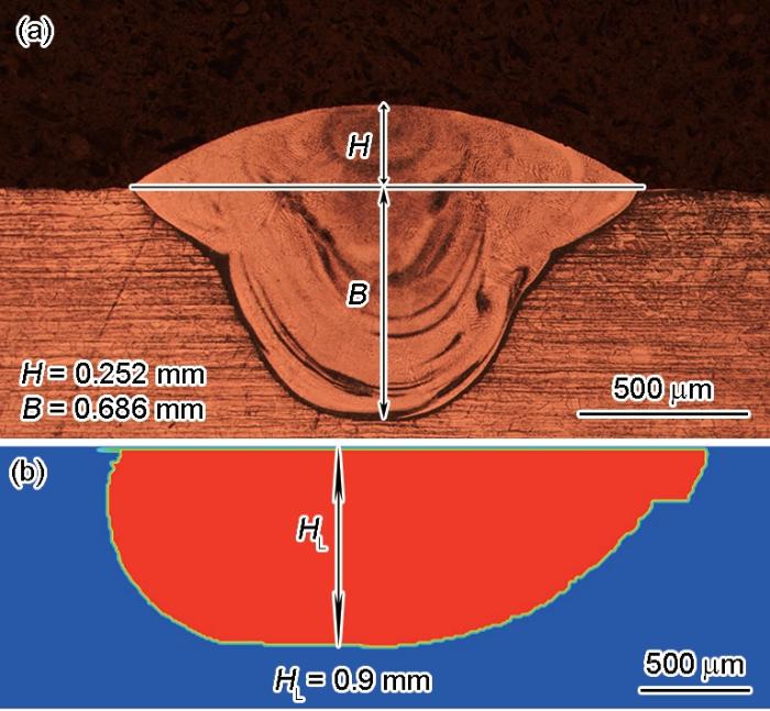
图4
时间t = 0.93 s时熔池形貌的OM像和模拟结果
Fig.4
OM image (a) and simulation result (b) of melt pool at t = 0.93 s (H—molten height; B—depth of fusion; HL = H + B)
该模型在初始化时,将流体域内划分成平均尺寸为83 μm的晶粒,并为每个晶粒设置随机生长方向,在激光辐照时发生熔化并随着光斑移动实现再凝固。如图5所示为t = 1.27 s时凝固组织形貌的模拟结果。在凝固过程中,在熔覆层底部,晶粒根据基材初始取向在温度场演化作用下实现外延生长,并逐渐发生倾斜;在熔覆层的中部,由于形核作用,部分枝晶被新生晶粒阻塞,并伴随新晶粒竞争生长;在熔覆层的顶部,由于顶部散热作用,熔体形核能力增强,晶粒明显增多,并且随着凝固继续,晶粒进一步长大。综上所述,由于凝固组织存在相互竞争生长,部分晶粒在温度场作用下择优生长,形成具有一定取向的组织形貌,该模拟结果与已有的研究结果[27,28]类似,进一步验证了本模型的合理性。由于本工作主要研究成分的分布,晶粒生长不再赘述。
图5
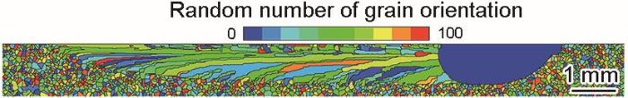
图5
t = 1.27 s时模拟的晶粒生长过程
Fig.5
Simulation of grain growth process at t = 1.27 s
3.2 温度场分布
图6为t = 0.15 s、t = 0.47 s、t = 0.80 s以及t = 1.13 s时的温度场演变云图,其中Tmax为当前时刻熔池中心最高温度,黑色线表示熔池轮廓线,此时fl = 0.5。熔池边界内为液相的Fe元素分布情况,熔池边界外为固相的Fe元素分布情况。由图可知,在t = 0.15 s之前激光的热输入量大于基体的热输出并形成熔池,此时熔池中心温度快速上升;在t = 0.15~0.45 s时因熔池尚未达到稳定,熔深持续增加,所以熔池温度继续增大;在t = 0.45 s后,熔池形貌达到稳定,此时激光的热输入量与熔池散热趋于平衡。在激光扫描方向上,熔池前方的等温线被压缩,等温线分布密集,温度梯度大,而熔池后方的等温线被拉伸,导致等温线分布稀疏,温度梯度较小。
图6
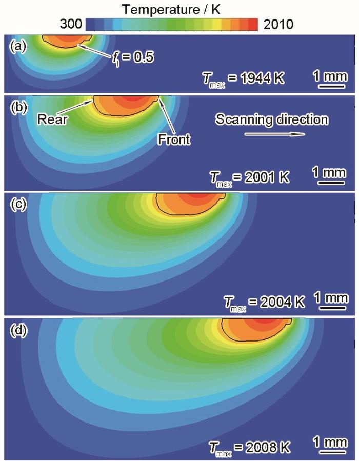
图6
不同时刻的温度场分布云图
Fig.6
Temperature field distributions at t = 0.15 s (a), t = 0.47 s (b), t = 0.80 s (c), and t = 1.13 s (d) (fl—volume fraction of liquild, Tmax—maximum temperature. Black lines show the contour lines of melt pool)
3.3 熔池流体流动特征
图7为t = 0.15 s、t = 0.47 s、t = 0.8 s以及t = 1.13 s时的流场矢量图,其中umax为当前时刻熔体的最大流动速率。在Marangoni剪切力的作用下,熔池具有由内向外的流动模式[29],而且熔池中的最大流动速率发生在熔池边缘附近。在t = 0.15 s时,熔池尚未完全成型,此时熔池中的umax为0.3219 m/s;在t = 0.15~0.47 s时,随着熔池持续吸收激光能量,熔体温度升高,在表面张力作用下,熔池中心的热量被熔体传导至熔池边缘,使得熔池尺寸不断增大,熔池边缘的温度梯度增大,umax增大;在t = 0.47 s以后,由于熔池基本成型,熔池中的umax趋于稳定。
图7
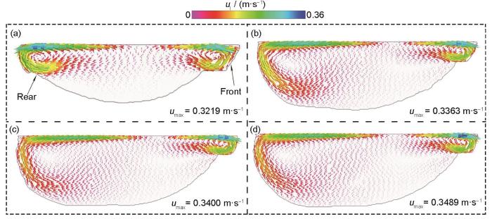
图7
不同时刻的流场分布矢量图
Fig.7
Vector plots of flow field distribution at t = 0.15 s (a), t = 0.47 s (b), t = 0.80 s (c), and t = 1.13 s (d) (ul—flow velocity of melt pool, umax—maximum flow velocity)
3.4 熔覆层中元素分布结果
图8为t = 1.17 s时Fe元素的分布云图。模拟结果显示,随着熔池深度不断增加,Fe元素含量也不断增加且有明显的分布不均匀现象。在熔深较小时,熔池中的熔体元素主要是粉末中的元素,凝固后的Fe元素含量也较低。随着熔深不断增大,在Marangoni力作用下,随着熔体的流动基体元素被不断地卷入熔池上部,熔池上部的元素被带到熔池底部,凝固后的Fe元素含量不断增加。由于熔池中的流动不断变化,使得熔池中的元素混合程度不同,熔池后端的液相线温度也不断地变化,熔池形貌也随之变化,形成浓度高、低相间分布呈条纹丝带状的偏析带。
图8
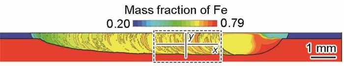
图8
t = 1.17 s时Fe元素的分布云图
Fig.8
Distribution nephogram of Fe element at t = 1.17 s
图9
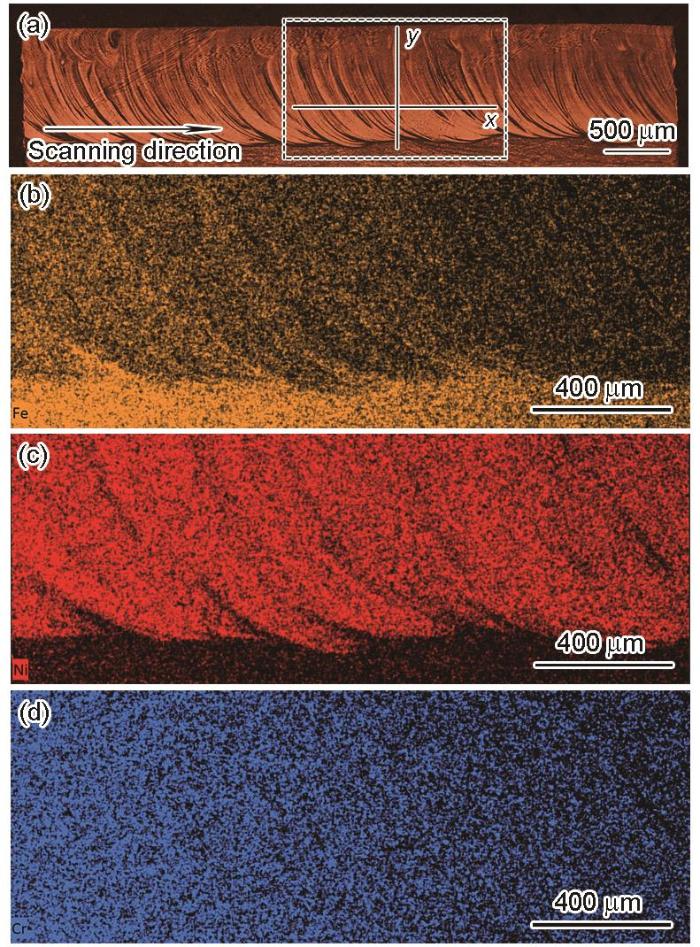
图9
沿激光扫描方向中间截面的OM像和元素的EDS面扫描
Fig.9
OM image of the middle section along the laser scanning direction (a); and EDS scanning maps of elements Fe (b), Ni (c), and Cr (d) of dashed area in Fig.9a
图10
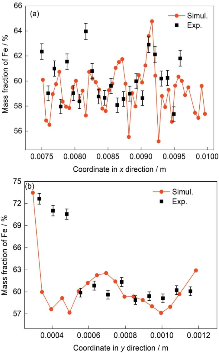
图10
x方向和y方向上的Fe元素含量的模拟(图8)与实验(图9a)结果对比图
Fig.10
Comparisons of simulated (Fig.8) and experim-ental (Fig.9a) results of Fe content in the x (a) and y (b) directions
3.5 偏析带形成机理
图11为t = 1.02 s、t = 1.03 s、t = 1.04 s、t = 1.05 s、t = 1.06 s以及t = 1.07 s时Fe元素分布的模拟结果。将熔池边界内的区域分为3个部分,红色部分主要为基板中的Fe元素含量,绿色部分主要为粉末中的Fe元素含量,剩下的橙黄色为基板与粉末中Fe元素的混合区域。熔池中液相线的温度随溶质浓度的不同而不同,在Marangoni力驱动下,当熔池底部的元素更多地被带入熔池后端时,熔池后端的液相线温度升高,促进了熔池后端的凝固,形成一道Fe元素的高浓度区域,如图11a~c所示。随时间增加,熔池后端形貌变为“鼓包”状,熔池中的流速增加,使得熔池前端的元素更多地被卷入熔池后端,熔池后端的液相线温度降低,推迟熔池后端的凝固,形成一道Fe元素的低浓度区域,如图11d~f所示。熔池后端形貌逐渐变得平坦,熔池中的流速逐渐降低,又会使得熔池底部的元素更多地被卷入熔池后端,这种现象会不断地出现在后续的凝固过程中。
图11
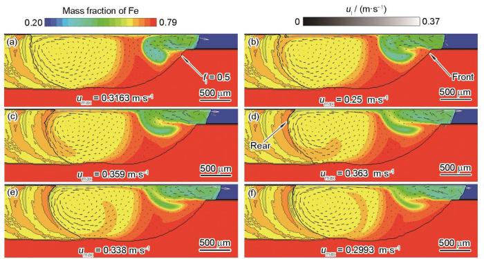
图11
不同时刻Fe元素的分布
Fig.11
Distributions of Fe element at t = 1.02 s (a), t = 1.03 s (b), t = 1.04 s (c), t = 1.05 s (d), t = 1.06 s (e), and t = 1.07 s (f) (Black lines show the contour lines of melt pool)
图12为偏析带形成过程的示意图,图中红色部分主要为基体中的Fe元素,绿色部分主要是粉末中的Fe元素,Tp表示粉末的液相线温度,Tb表示基体的液相线温度,Ta为实际凝固的液相线温度。熔池底部(红色)的Fe元素被流动带入熔池后端,熔池后端的液相线温度升高,使得Ta偏向Tb,凝固时间提前,熔池后端快速凝固,形成Fe元素的高浓度区域,如图12a和b所示。当熔池前端(绿色)的Fe元素更多地流入熔池后端,熔池后端的液相线温度降低,使得Ta偏向Tp,减缓熔池后端的凝固,如图12c所示。随着凝固的进一步进行,熔池后端边界向前推进,形成Fe元素的低浓度区域,如图12d所示。固/液界面的推移速率由界面胞与邻胞的溶质浓度差异确定,而熔池中的流动存在波动,使得熔池后端的形貌不断发生变化,凝固后的Fe元素浓度也存在差异,该现象会不断出现在后续的凝固过程中。因此,增加熔池中元素混合的均匀性,可以降低偏析程度,在实验过程中,可以适当提高激光功率和降低扫描速率以便提高熔覆层的质量。
图12
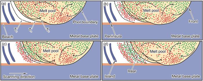
图12
偏析带形成的示意图
Fig.12
Schematics of the formation of the segregation bands
(a) Ta at the rear end of the molten pool tends to Tb (Tp—liquidus temperature of powder; Ta—actual solidification liquidus temperature; Tb—liquidus temperature of matrix; Red and green dots represent Fe element in matrix and in powder, respectively)
(b) solidification creates a region of high concentration of Fe element
(c) Ta at the rear end of the molten pool tends to Tp
(d) solidification creates a region of low concentration of Fe element
4 结论
(1) 基于元胞自动机方法和Eulerian多相流算法建立了在316L不锈钢基板上激光熔覆IN718合金的二维熔化凝固模型,模拟结果表明,Fe元素含量高、低相间分布,呈条纹丝带状,与实验结果吻合较好,证明了本模型的可靠性。
(2) 熔池中的熔体在Marangoni力驱动下,将熔池底部和熔池前端的元素卷入熔池后端,使得熔池中的液相线温度发生变化,导致熔池后端的形貌在温度场和溶质场共同作用下发生周期性波动,进而影响熔池中流体的流速,最终造成Fe元素分布不均匀,形成偏析带。
参考文献
Microstructural characteristics and crack formation in additively manufactured bimetal material of 316L stainless steel and Inconel 625
[J].
Influence of macrosegregation on solidification cracking in laser clad ultra-high strength steels
[J].
Macrosegregation in dissimilar-metal fusion welding
[J].
Effect of dilution and macrosegregation on corrosion resistance of laser clad Aermet100 steel coating on 300M steel substrate
[J].
Modeling of thermal behavior and mass transport in multi-layer laser additive manufacturing of Ni-based alloy on cast iron
[J].
Investigation on composition distribution of dissimilar laser cladding process using a three-phase model
[J].
Fluid flow and solute dilution in laser linear butt joining of 304SS and Ni
[J].
Experimentally validated predictions of thermal history and microhardness in laser-deposited Inconel 718 on carbon steel
[J].
Thermal-solutal-fluid flow of channel segregation during directional solidification of single-crystal nickel-based superalloys
[J].
A modified cellular automaton model for the quantitative prediction of equiaxed and columnar dendritic growth
[J].
Since the characteristic of dendrite is an important factor determining the performance of castings, a two-dimensional cellular automaton model with decentered square algorithm is developed for quantitatively predicting the dendritic growth during solidification process. The growth kinetics of solid/liquid interface are determined by the local equilibrium composition and local actual liquid composition, and the calculation of the solid fraction increment is based on these two compositions to avoid the solution of growth velocity. In order to validate the developed model, quantitative simulations of steady-state dendritic features over a range of undercooling was performed and the results exhibited good agreement with the predictions of LGK (Lipton-Glicksman-Kurz) model. Meanwhile, it is demonstrated that the proposed model can be applied to simulate multiple equiaxed dendritic growth, as well as columnar dendritic growth with or without equiaxed grain formation in directional solidification of Al-Cu alloys. It has been shown that the model is able to simulate the growth process of multi-dendrites with various preferential orientations and can reproduce a wide range of complex dendritic growth phenomena such as nucleation, coarsening of dendrite arms, side branching in dendritic morphologies, competitive growth as well as the interaction among surrounding dendrites.
Modeling of dendritic evolution of continuously cast steel billet with cellular automaton
[J].
Numerical modeling of solidification morphologies and segregation patterns in cast dendritic alloys
[J].
A quantitative dendrite growth model and analysis of stability concepts
[J].
Virtual front tracking model for the quantitative modeling of dendritic growth in solidification of alloys
[J].
Numerical simulation of dendrite grain growth of DD6 superalloy during directional solidification process
[J].Modern aero and power industry needs high-performance gas turbine. Directional solidification (DS) columnar grain and single crystal (SX) blade as key parts of gas turbine serve in heavy stress and high temperature conditions. The DS and SX blade are mainly produced by high rapid solidification (HRS) method, and HRS is one of useful DS technology, which has a property that the heat dissipating ways are changing during the process and the temperature gradients will vary correspondingly. The dendrite grain arrays were the substructure of a DS or SX blade. The structure of the dendrite grain arrays influences the mechanical property of the final casting very much, but is seriously affected by the solidification parameters, such as temperature gradient. In this work, the dendrite grain growth of DD6 superalloy was studied based on cellular automaton-finite difference (CA-FD) model concerning the HRS method's macro solidification parameters. Mathematic models for dendrite grain growth controlled by temperature field and solute field were built to describe the competitive growth and morphology evolution of dendrite grains. Then the dendrite calculation model was coupled with the models of DS process calculation, and some HRS solidification parameters were included, such as withdrawal rate, pouring temperature, etc. The coupled models were used to predict the dendrite grain competitive growth of DD6 superalloy during the DS process. The variation of solute distribution and the dynamic adjustment of dendritic spacing during the process could be predicted by simulating calculation. The DS experiment was carried out with a cylinder sample, and dendrite grains' distribution in the transverse and longitude section was observed by OM and SEM. Then the simulated dendritic morphology was compared with that by experiment. The primary and secondary dendritic spacing by experiment and simulation were measured, and the compared results revealed that as the DS process going on the temperature gradient decreased gradually and the primary dendritic spacing was increasing. So simulation results of the DS dendritic competitive growth were validated by the experiment results, and the proposed models could predict the dendrite grain morphology and the adjustments of DS dendritic spacing of DD6 superalloy very well.
DD6高温合金定向凝固枝晶生长的数值模拟研究
[J].
Numerical simulation of solute undercooling influenced columnar to equiaxed transition of Fe-C alloy with cellular automaton
[J].
Cellular automaton simulation of three-dimensional dendrite growth in Al-7Si-Mg ternary aluminum alloys
[J].
Simulation of channel segregation using a two-phase columnar solidification model—part i: Model description and verification
[J].
Effects of process parameters upon chromium element distribution in laser-cladded 316L stainless steel
[J].
工艺参数对316L不锈钢激光熔覆层中Cr元素分布的影响
[J].
Simulation of the dendrite growth during directional solidification under steady magnetic field using three-dimensional cellular automaton method coupled with eulerian multiphase
[J].
A two-dimensional model for the quantitative simulation of the dendritic growth with cellular automaton method
[J].
Cellular automaton modeling of microstructure evolution during alloy solidification
[J].
合金凝固过程中显微组织演化的元胞自动机模拟
[J].元胞自动机(cellular automaton, CA)方法能够有效地描述凝固过程中显微组织形貌的复杂演化过程, 且计算效率较高, 展现出良好的实际应用潜力. 近20年来, CA模型取得了很大的进展. 本文简要综述几种模拟凝固组织的CA模型, 包括纯扩散和对流作用下的枝晶生长、共晶凝固、多元合金中的热力学和动力学耦合、枝晶耦合凝固气孔的生长、以及多尺度的耦合模拟. 最后, 对今后CA模型的发展提出作者的几点思考.
Multiscale modeling of transport phenomena and dendritic growth in laser cladding processes
[J].
In situ X-ray imaging of defect and molten pool dynamics in laser additive manufacturing
[J].The laser-matter interaction and solidification phenomena associated with laser additive manufacturing (LAM) remain unclear, slowing its process development and optimisation. Here, through in situ and operando high-speed synchrotron X-ray imaging, we reveal the underlying physical phenomena during the deposition of the first and second layer melt tracks. We show that the laser-induced gas/vapour jet promotes the formation of melt tracks and denuded zones via spattering (at a velocity of 1 ms(-1)). We also uncover mechanisms of pore migration by Marangoni-driven flow (recirculating at a velocity of 0.4 m s(-1)), pore dissolution and dispersion by laser re-melting. We develop a mechanism map for predicting the evolution of melt features, changes in melt track morphology from a continuous hemi-cylindrical track to disconnected beads with decreasing linear energy density and improved molten pool wetting with increasing laser power. Our results clarify aspects of the physics behind LAM, which are critical for its development.
Real-time monitoring of laser powder bed fusion process using high-speed X-ray imaging and diffraction
[J].We employ the high-speed synchrotron hard X-ray imaging and diffraction techniques to monitor the laser powder bed fusion (LPBF) process of Ti-6Al-4V in situ and in real time. We demonstrate that many scientifically and technologically significant phenomena in LPBF, including melt pool dynamics, powder ejection, rapid solidification, and phase transformation, can be probed with unprecedented spatial and temporal resolutions. In particular, the keyhole pore formation is experimentally revealed with high spatial and temporal resolutions. The solidification rate is quantitatively measured, and the slowly decrease in solidification rate during the relatively steady state could be a manifestation of the recalescence phenomenon. The high-speed diffraction enables a reasonable estimation of the cooling rate and phase transformation rate, and the diffusionless transformation from β to α phase is evident. The data present here will facilitate the understanding of dynamics and kinetics in metal LPBF process, and the experiment platform established will undoubtedly become a new paradigm for future research and development of metal additive manufacturing.
Fluid and particle dynamics in laser powder bed fusion
[J].
Numerical investigation of effects of nucleation mechanisms on grain structure in metal additive manufacturing
[J].
Three-dimensional grain growth during multi-layer printing of a nickel-based alloy Inconel 718
[J].Heterogeneous grain structure is a source of the inhomogeneity in structure and properties of the metallic components made by multi-layer additive manufacturing (AM). During AM, repeated heating and cooling during mull-layer deposition, local temperature gradient and solidification growth rate, deposit geometry, and molten pool shape and size govern the evolution of the grain structure. Here the effects of these causative factors on the heterogeneous grain growth during multi-layer laser deposition of Inconel 718 are examined by a Monte Carlo method based grain growth model. It is found that epitaxial columnar grain growth occurs from the substrate or previously deposited layer to the curved top surface of the deposit. The growth direction of these columnar grains is controlled by the molten pool shape and size. The grains in the previously deposited layers continue to grow because of the repeated heating and cooling during the deposition of the successive layers. Average longitudinal grain area decreases by approximately 80% when moving from the center to the edge of the deposit due to variable growth directions dependent on the local curvatures of the moving molten pool. The average horizontal grain area increases with the distance from the substrate, with a 20% increase in the horizontal grain area in a short distance from the third to the eighth layer, due to competitive solid-state grain growth causes increased grain size in previous layers.
Revealing internal flow behaviour in arc welding and additive manufacturing of metals
[J].Internal flow behaviour during melt-pool-based metal manufacturing remains unclear and hinders progression to process optimisation. In this contribution, we present direct time-resolved imaging of melt pool flow dynamics from a high-energy synchrotron radiation experiment. We track internal flow streams during arc welding of steel and measure instantaneous flow velocities ranging from 0.1ms(-1) to 0.5ms(-1). When the temperature-dependent surface tension coefficient is negative, bulk turbulence is the main flow mechanism and the critical velocity for surface turbulence is below the limits identified in previous theoretical studies. When the alloy exhibits a positive temperature-dependent surface tension coefficient, surface turbulence occurs and derisory oxides can be entrapped within the subsequent solid as result of higher flow velocities. The widely used arc welding and the emerging arc additive manufacturing routes can be optimised by controlling internal melt flow through adjusting surface active elements.
