


通常复相材料中相间变形的不均匀性会在组元相界处产生明显的应力集中,使相界处的内能显著升高,导致相界成为微裂纹形核和扩展的位置。由此,Su等[6]强调复合材料的强化和断裂机制在很大程度上取决于界面的强度。同时,裂纹的萌生与各相的分布特征[7,8]、微观结构形态[9~13]、晶粒尺寸[14]等密切相关。对于常见的铁素体-马氏体双相不锈钢,观察到了2种损伤机制:第一种机制发生在马氏体-铁素体相界面[15~18],第二种机制是马氏体开裂[19,20],并以第一种机制为主导[21~23]。Moallemi等[24]根据双相钢的对比研究认为,微观结构的复杂性会导致其损伤和断裂机制达到一种更复杂的程度。对于TRIP型双相不锈钢而言,由于相变马氏体的引入,初始奥氏体组织逐渐转变为相变马氏体和残余奥氏体,且相变马氏体的体积分数一直在动态变化中,甚至约50%的初始奥氏体能够发生相变转变成马氏体[4,25,26],使得材料微观结构处于不断变化的复杂状态中。更重要的,不同类型的相界(残余奥氏体/铁素体、铁素体/相变马氏体、残余奥氏体/相变马氏体)具有不同的界面性质和特征,导致界面的损伤顺序、裂纹形核及演化特征等更加复杂。目前对TRIP型双相不锈钢在变形过程中微裂纹的形核及演化规律尚无定论。
本工作以一种具有TRIP效应的双相不锈钢Fe-19.6Cr-2Ni-2.9Mn-1.6Si为研究对象,着重观测材料在拉伸失稳前(工程应变εE = 55%)产生的微裂纹特征,统计微裂纹分布位置,基于微裂纹周围各相分布特征,分析相变马氏体和残余奥氏体的分布对微裂纹形核和扩展的影响,分析微裂纹形核和扩展的微观机理,以期进一步澄清具有TRIP效应的双相不锈钢的损伤演化机制。
1 实验方法
实验用TRIP型双相不锈钢Fe-19.6Cr-2Ni-2.9Mn-1.6Si由20 kg真空感应炉冶炼,抽真空后充入高纯度N2进行精炼。铸锭经1150 ℃高温加热保温后锻造开坯,并在1100 ℃下加热保温30 min后油冷,进行固溶处理。利用Q10 A+显微硬度计测定材料初始两相硬度,并通过配备电子背散射衍射(EBSD)系统的Sigma 500/VP超高分辨扫描电子显微镜(SEM)测定材料的初始组织特征。
图1

图1
样品示意图及SEM观测区域和微裂纹分布位置
Fig.1
Schematic of sample (a) and observation area for SEM and distribution of microcracks (b) (unit: mm)
对观测平面进行机械抛光,之后在20 ℃下施加12 V的电势,将试样置于体积分数为5%HClO4 + 95%C2H5OH的均匀混合电解液中对其进行5 s的电解抛光。为观测微裂纹的位置特征,通过SEM对观测平面的中心区域(5 mm × 3 mm)进行全域搜寻,搜寻尺寸为250 μm × 250 μm,因此中心区域(5 mm × 3 mm)可分为20 × 12个小观测区域,如图1b所示,在小区域内寻找微裂纹,记录微裂纹的所在区域。在整个5 mm × 3 mm的观测区域内共搜索到微裂纹20条,微裂纹的分布位置由图1b中红色小格子标出。为进一步探究微裂纹的形核及扩展规律,在20 kV下,通过EBSD测定具有明显形核或扩展特征的微裂纹周围区域(即图1b中红色格子区域内)的组织分布和晶粒取向特征。
2 实验结果
2.1 Fe-19.6Cr-2Ni-2.9Mn-1.6Si钢的初始组织特征
Fe-19.6Cr-2Ni-2.9Mn-1.6Si 钢初始组织特征如图2所示。可见,奥氏体和铁素体两相呈带状均匀分布(图2a,深色灰色为奥氏体γ,亮白色为铁素体α),经统计两相体积比Vγ ∶Vα ≈ 48∶52,带状组织长宽比约为6∶1。通过EBSD观察,对照Fe-19.6Cr-2Ni-2.9Mn-1.6Si钢初始的两相分布图和反极图(IPF),如图2b和c所示,可见固溶处理后,两相都有完全再结晶的纤维型微观结构,两相组织内观察不到亚结构,也未观察到微裂纹。晶粒在各相内均匀分布,其中沿带状相的长轴方向,奥氏体的平均晶粒尺寸为26.5 μm,铁素体平均晶粒尺寸为27.8 μm;沿带状相的短轴方向,奥氏体平均晶粒尺寸为23.4 μm,铁素体平均晶粒尺寸为24.3 μm。硬度测试结果表明,奥氏体硬度约为274 HV,铁素体硬度约为262 HV。
图2
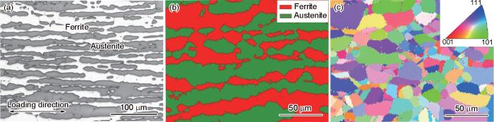
图2
Fe-19.6Cr-2Ni-2.9Mn-1.6Si钢初始组织特征
Fig.2
Initial microstructure of the as-received Fe-19.6Cr-2Ni-2.9Mn-1.6Si steel
(a) SEM image (b) phase distribution (c) inverse pole figure (IPF)
2.2 单调加载力学性能
图3为Fe-19.6Cr-2Ni-2.9Mn-1.6Si钢单调加载工程应力-工程应变曲线(图3a)和真应力-真应变及加工硬化率曲线(图3b)。可见,Fe-19.6Cr-2Ni-2.9Mn-1.6Si钢具有良好的力学性能,其屈服强度为567 MPa,抗拉强度可达835 MPa,断裂延伸率高达70%。当变形量达到20%左右时(真应变约为0.175),流动应力再次快速增加,真应力-应变曲线大体呈“S”型。随变形的进行,加工硬化率先降低再增加至峰值后再次降低直至断裂,表现出“三阶段”硬化特征,如图3b所示。由此推断,Fe-19.6Cr-2Ni-2.9Mn-1.6Si钢中奥氏体相在变形过程中发生了明显的形变诱导马氏体相变,产生了TRIP效应,使得强度和塑性明显提高。可以通过Considére标准预测失稳点[27,28],该标准表示为:
图3
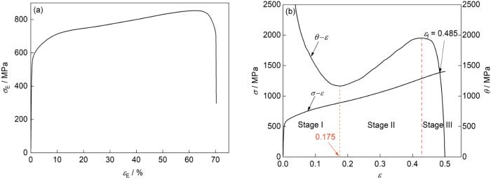
图3
Fe-19.6Cr-2Ni-2.9Mn-1.6Si钢的单调加载力学性能
Fig.3
Mechanical properties of Fe-19.6Cr-2Ni-2.9Mn-1.6Si steel during monotonic loading (σE—engineering stress, εE—engineering strain,
(a) engineering stress-engineering strain curve
(b) true stress-true strain and work hardening rate curves
式中,θ为加工硬化率,σ和ε分别为真应力和真应变。当满足σ = θ条件时,即当应变达到图3b中2条曲线相交点时,材料将会发生塑性失稳,以此确定材料的失稳点应变为εf = 0.485 (εE约为62.4%)。到达失稳点后,随着应变继续增加,材料将发生颈缩,最后断裂。因此,本工作采用拉伸εE = 55%后的试样进行后续实验,以便试样中能有一定数量的微裂纹。
2.3 微裂纹分布特征
当εE = 55%时,初始奥氏体相内已经产生了一定量的马氏体相变组织,此时观察微裂纹的分布状态,结果如图4所示。依据初始奥氏体区域的金属光泽较铁素体差,可区分出初始奥氏体区域与铁素体相。图4a中存在2段相界微裂纹,2段微裂纹在一条相界上,分布距离非常接近,仅5~10 μm。图4b中的相界微裂纹,由于受到凸起的铁素体相的阻断,造成两段分布特征。图4c中的相界微裂纹较短,相界位置有形核的微裂纹孔洞,仅存在较短的扩展特征,微裂纹长度仅3 μm左右。在图4d中存在3个微裂纹孔洞,这3个微裂纹孔洞都处在同一条相界上,并且在图中上侧初始奥氏体组织内存在一条与相界相交的初始奥氏体晶界。图4e、f和g中的相界微裂纹长度分别约为10、15和20 μm。图4h为明显的初始奥氏体相内的晶界裂纹,在图中右侧存在一个尖锐的铁素体相,该条裂纹也位于相界附近。图4i和j都为铁素体相内的晶界裂纹,其中,在图4i的微裂纹右侧存在一个带有明显尖角的初始奥氏体相,而图4j的微裂纹两侧均存在着有尖角的初始奥氏体相。
图4
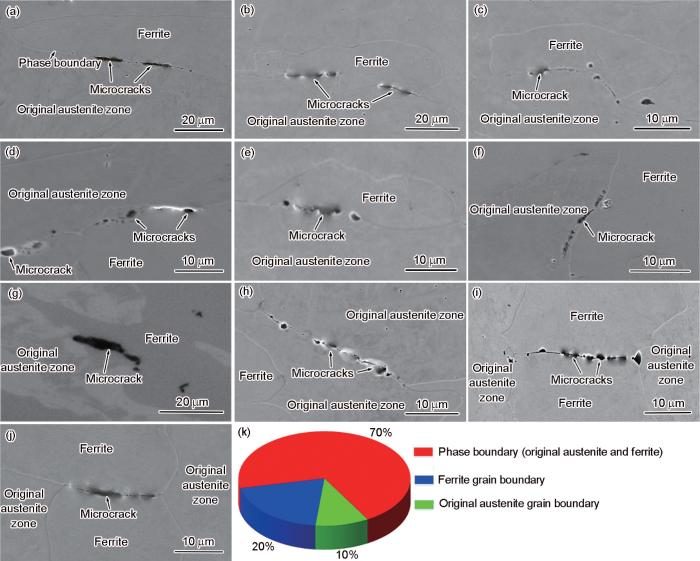
图4
Fe-19.6Cr-2Ni-2.9Mn-1.6Si钢中微裂纹位置统计
Fig.4
Statistics of microcrack locations of Fe-19.6Cr-2Ni-2.9Mn-1.6Si steel
(a-g) microcracks at phase boundary
(h) microcracks at original austenite grain boundary (i, j) microcracks at ferrite grain boundary (k) statistical pie chart
2.4 微裂纹附近的各相分布特征
利用EBSD观察各类型微裂纹附近的各相分布状态,尤其是微裂纹附近相变马氏体的分布。图5展示了2个尚在形核阶段的微裂纹孔洞,孔洞周边未见明显的扩展特征,2个微裂纹孔洞在同一条相界上,距离约25 μm。依据SEM像(图5a),可以确定这2个微裂纹孔洞均分布在初始奥氏体/铁素体相界位置。基于相分布特征(图5b),可以看出初始奥氏体相中存在明显的马氏体相变,特别在2个微裂纹孔洞的奥氏体侧(图中裂纹孔洞的下侧)均存在相变马氏体。通过IPF (图5c)可见,2个微裂纹孔洞上侧的铁素体组织保持相同的晶格取向,为一个铁素体晶粒。而微裂纹孔洞下侧的长条状初始奥氏体组织中,依据残余奥氏体的晶粒取向关系,可以确定存在2个初始奥氏体晶粒。左侧的微裂纹孔洞A分布在相界与奥氏体晶界交汇位置,而右侧微裂纹B的奥氏体一侧存在一条明显的孪晶带。
图5
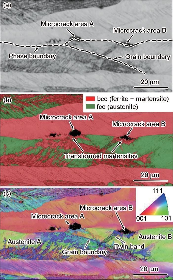
图5
初始奥氏体/铁素体相界位置的微裂纹特征
Fig.5
Characteristics of microcracks at the original austenite/ferrite phase boundary
(a) SEM image
(b) phase distribution
(c) IPF
图6
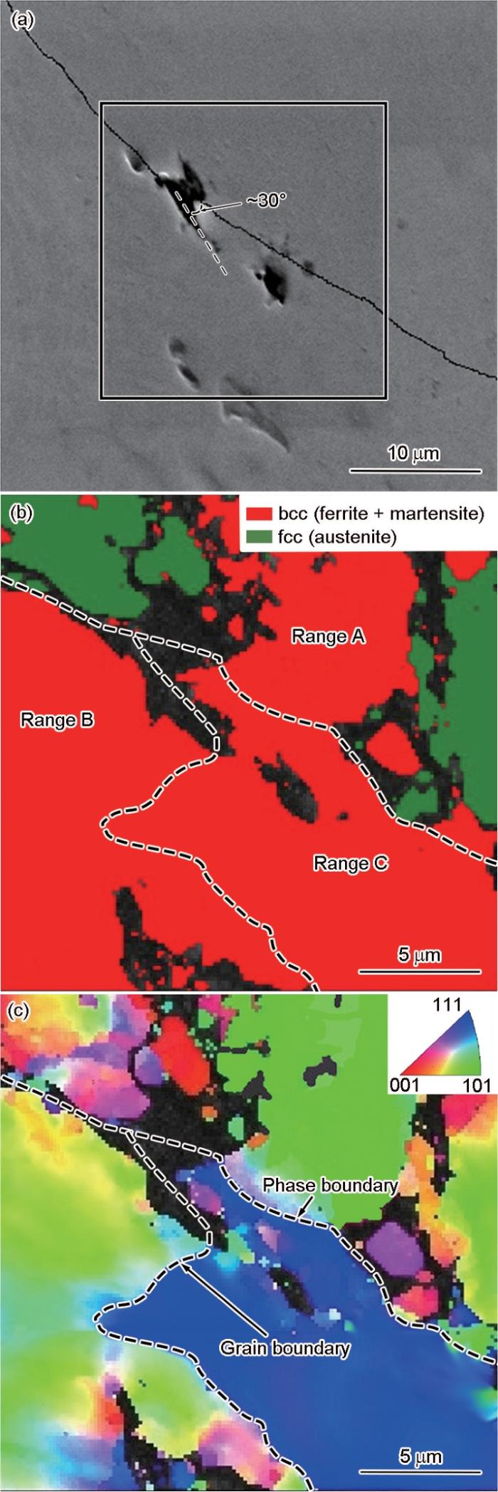
图6
初始奥氏体/铁素体相界的微裂纹的形核并沿铁素体晶界扩展趋势
Fig.6
Nucleation of a microcrack at the original austenite/ferrite phase boundary and the propagation trend of the microcrack along the ferrite grain boundary
(a) SEM image
(b) phase distribution
(c) IPF
图7
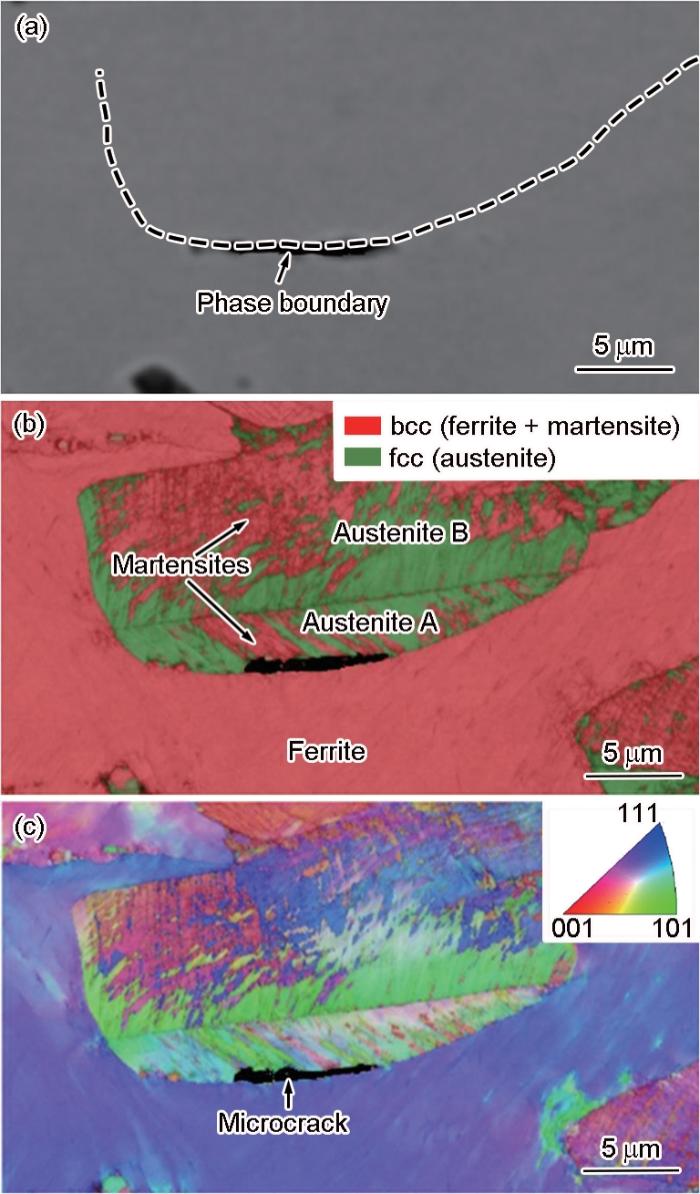
图7
初始奥氏体/铁素体相界上的微裂纹扩展特征
Fig.7
Propagation characteristics of a microcrack on the original austenite/ferrite phase boundary
(a) SEM image
(b) phase distribution
(c) IPF
图8
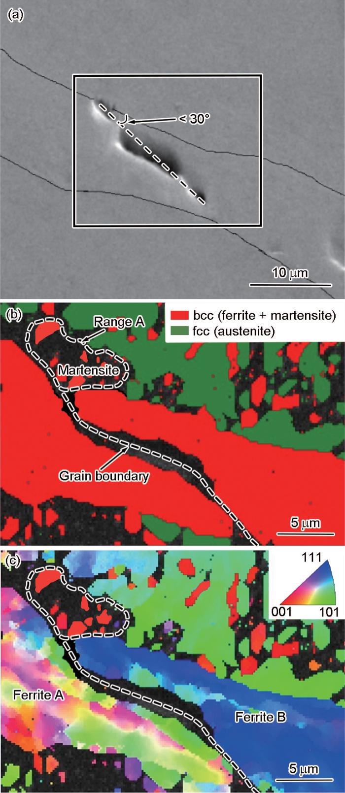
图8
铁素体晶界上的微裂纹特征
Fig.8
Characteristics of a microcrack on ferrite grain boundary
(a) SEM image
(b) phase distribution
(c) IPF
图9a展示了一条微裂纹,依据SEM的观测特征,微裂纹可以分成2段相界微裂纹(区域A和B)和1段初始奥氏体相内的微裂纹(区域C)。基于相图中各相分布(图9b)和IPF分布特征(图9c),区域A的微裂纹孔洞在初始奥氏体和铁素体的相界位置。在微裂纹孔洞的初始奥氏体一侧(图中区域A微裂纹的上侧),奥氏体发生了大量的马氏体相变,在微裂纹的孔洞位置形成了相变马氏体/残余奥氏体/铁素体多相交汇特征,这种特征与图6的裂纹形核特征一致。同时在此微裂纹的铁素体侧(区域A微裂纹孔洞下方),依据取向差异确定铁素体相内包含2个铁素体晶粒,可见微裂纹孔洞处在形核马氏体和铁素体相界与铁素体晶界交汇的位置,此特征与图8的微裂纹特征一致。区域B的微裂纹孔洞处在残余奥氏体和铁素体的相界与铁素体晶界及奥氏体晶界的多界面交汇。区域C的微裂纹在初始奥氏体相内,两侧均分布着不同取向的马氏体。依据残余奥氏体的取向,确定区域C的微裂纹处于初始奥氏体的晶界位置,由于晶界两侧奥氏体均发生了马氏体相变,区域C的微裂纹实际处于相变马氏体的晶界位置。
图9
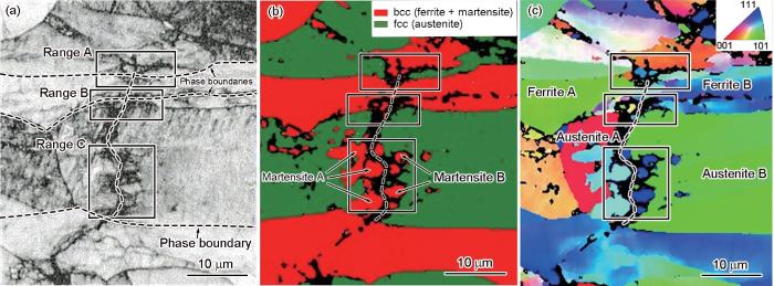
图9
初始奥氏体晶界的裂纹特征
Fig.9
Characteristics of microcracks at original austenite grain boundary
(a) SEM image (b) phase distribution (c) IPF
3 分析与讨论
3.1 微裂纹的形核特征
观察微裂纹周围各相分布特征可以发现,微裂纹孔洞主要形核于初始奥氏体/铁素体相界位置,且在微裂纹形核位置的周围都分布有相变马氏体。因此可进一步确认微裂纹的形核均受到相变马氏体的影响。由于马氏体与铁素体的力学性能差异最大,在各相应变配分中,马氏体和铁素体的配分应变显示了最大的应变不相容性[29,30],因此微裂纹在相变马氏体与铁素体相界位置更易形核。对相界裂纹的进一步分析可以发现,微裂纹的形核不仅受到相变马氏体与铁素体应变不相容的影响,还受到其他类型界面的影响,如相变马氏体、铁素体与残余奥氏体的相界(图6和图9区域A的微裂纹),初始奥氏体晶界(图5的微裂纹A),铁素体晶界(图8的微裂纹),甚至孪晶界(图5的微裂纹B)。基于主要微裂纹的形核特征,归纳3类微裂纹形核规律。第一类为相变马氏体/铁素体/残余奥氏体三相的交汇位置(图10a中C点所示),由于三相的性能差异,导致三相的交汇点成为相间变形最不协调的位置,造成微裂纹的形核;第二类为相变马氏体/铁素体相界和铁素体晶界交叉位置(图10b中D点所示);第三类为相变马氏体/铁素体相界和初始奥氏体晶界交叉位置(图10c中E点所示)。微裂纹形核位置通常在多类型界面的交汇处,因此微裂纹的形核可能是由2类,甚至是3类形核规律的共同作用导致的,如图9区域A的微裂纹既是三相的交汇位置(第一类形核特征),又是铁素体晶界与相界的交汇点(第二类形核特征)。
图10

图10
微裂纹形核特征示意图
Fig.10
Schematics of microcrack nucleation characteristics
(a) nucleation at the intersection position of transformed martensite/ferrite/residual austenite
(b) nucleation at the intersection position of the ferrite/martensite phase boundary and ferrite grain boundary
(c) nucleation at the intersection of ferrite/martensite phase boundary and original austenite grain boundary
3.2 微裂纹的扩展特征
由于微裂纹在相界位置形核,并且形核位置主要集中在多界面(相界或晶界)的交汇处,在其扩展路径上存在多种可能的情况。通过对微裂纹周围各相分布特征的观察,可以确定3类主要的裂纹扩展路径。
第一类裂纹扩展路径为初始奥氏体/铁素体的相界,如图11a所示,是裂纹最主要的扩展路径,占比最多,约70%的微裂纹都分布在初始奥氏体/铁素体的相界位置。微裂纹在初始奥氏体/铁素体相界上容易扩展的原因主要包含2个方面:其一,由于奥氏体与铁素体材料性能的差异,及取向的差异,造成相间的变形不协调性较相内晶粒间的更加严重,这与双相钢中相界开裂行为的原因相同[17,18,31];其二,在变形过程中亚稳态奥氏体发生了马氏体相变,马氏体为材料组织中的硬相,尤其是界面附近形核的马氏体,包括与铁素体接触分布的大块相变马氏体或与奥氏体交错分布的带状马氏体(如图7的马氏体分布所示),均强化了初始奥氏体相,加剧了相界两侧初始奥氏体与铁素体的不协调变形特征[4,32],造成微裂纹在初始奥氏体与铁素体相界上形核和扩展。
图11
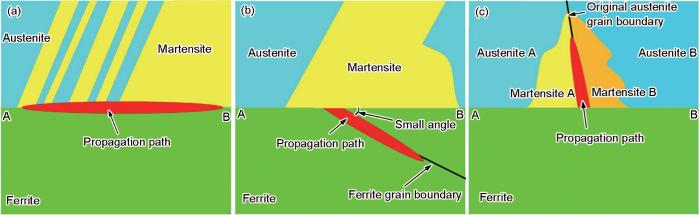
图11
裂纹扩展路径示意图
Fig.11
Schematics of crack propagation paths
(a) crack propagation along the original austenite/ferrite phase boundary
(b) crack propagation along ferrite grain boundary with a smaller angle to the phase boundary
(c) crack propagation along transformed martensite (original austenite) grain boundary
图12
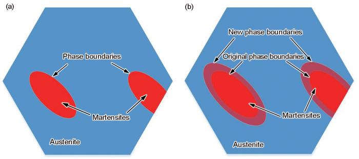
图12
奥氏体/马氏体相界未形核裂纹原因示意图
Fig.12
Schematics of non-nucleated crack at austenite/martensite phase boundary
(a) deformation of pre nucleated martensite and austenite
(b) formation of new phase boundaries due to martensite growth
4 结论
(1) TRIP型双相不锈钢Fe-19.6Cr-2Ni-2.9Mn-1.6Si在拉伸至εE = 55% (塑性失稳前)时,钢中的微裂纹按其位置特征,可分为3类:以分布在初始奥氏体与铁素体相界位置的微裂纹为主,微裂纹数量约占裂纹总数的70%;分布在铁素体晶界的微裂纹次之,微裂纹数量约占总数的20%;约10%的微裂纹分布在初始奥氏体晶界位置。而在奥氏体与马氏体相界上很难形成微裂纹。
(2) 微裂纹的形核均受到相变马氏体的影响,相变马氏体与铁素体相界面是微裂纹形核的主要位置。微裂纹的形核易于发生在多类型界面的交汇位置,归纳3类主要的微裂纹形核规律:第一类为相变马氏体/铁素体/残余奥氏体三相的交汇位置;第二类为相变马氏体/铁素体相界和铁素体晶界交叉位置;第三类为相变马氏体/铁素体相界和初始奥氏体晶界交叉位置。
(3) 由于相间的不协调变形特征,并且在相变马氏体的影响下强化了初始奥氏体组织,导致在初始奥氏体与铁素体相界上裂纹更容易扩展,沿相界扩展是最主要的裂纹扩展路径。形核的微裂纹还容易沿与相界(初始奥氏体与铁素体)夹角较小(< 30%)的铁素体(软相)晶界扩展。另外,马氏体相变能够减缓奥氏体相内微裂纹的扩展,而马氏体是硬相,变形协调能力差,因此有少量微裂纹沿着相变马氏体晶界扩展。
参考文献
Intermediate stacking fault and twinning induced cooperative strain evolution of dual phase in lean duplex stainless steels with excellent cryogenic strength-ductility combinations
[J].
Effect of austenitic texture on tensile behavior of lean duplex stainless steel with transformation induced plasticity (TRIP)
[J].
Design of a novel Mn-based 1 GPa duplex stainless TRIP steel with 60% ductility by a reduction of austenite stability
[J].
Micromechanics of plastic deformation and phase transformation in a three-phase TRIP-assisted advanced high strength steel: Experiments and modeling
[J].
Transformation-induced plasticity (TRIP) in advanced steels: A review
[J].
Effects of interphase strength on the damage modes and mechanical behaviour of metal-matrix composites
[J].
On key factors influencing ductile fractures of dual phase (DP) steels
[J].
Influence of volume fraction and distribution of martensite phase on the strain localization in dual phase steels
[J].
Strain localization and damage in dual phase steels investigated by coupled in-situ deformation experiments and crystal plasticity simulations
[J].
Microstructural influence on small fatigue cracks in a ferritic-martensitic steel
[J].
The lattice strain ratio in characterizing the grain-to-grain interaction effect and its specific insight on the plastic deformation of polycrystalline materials
[J].
Multiple mechanisms of lath martensite plasticity
[J].
Plasticity of lath martensite by sliding of substructure boundaries
[J].
Deformation and fracture mechanisms in fine- and ultrafine-grained ferrite/martensite dual-phase steels and the effect of aging
[J].
Effect of the martensite distribution on the strain hardening and ductile fracture behaviors in dual-phase steel
[J].
Real microstructure based micromechanical model to simulate microstructural level deformation behavior and failure initiation in DP 590 steel
[J].
FEM modeling of the flow curves and failure modes of dual phase steels with different martensite volume fractions using actual microstructure as the representative volume
[J].
Micromechanical modeling of damage mechanisms in dual-phase steel under different stress states
[J].
Micromechanics based modelling of fatigue crack initiation of high strength steel
[J].
A comparative study on mechanical behavior and damage scenario of DP600 and DP980 steels
[J].
Effect of microstructure pattern on the strain localization in DP600 steels analyzed using combined in-situ experimental test and numerical simulation
[J].
Effect of martensite morphology and volume fraction on strain hardening and fracture behavior of martensite-ferrite dual phase steel
[J].
Micro-damage initiation in ferrite-martensite DP microstructures: A statistical characterization of crystallographic and chemical parameters
[J].
Strain hardening analysis and deformation micromechanisms in high strength-high ductility metastable duplex stainless steels: Role of sustained stacking faults in the work hardening
[J].
A new coupled thermomechanical framework for modeling formability in transformation induced plasticity steels
[J].
Effect of kinematic stability of the austenite phase on phase transformation behavior and deformation heterogeneity in duplex stainless steel using the crystal plasticity finite element method
[J].
Revisiting the Considère criterion from the viewpoint of dislocation theory fundamentals
[J].
Transformation-induced plasticity characteristics and temperature dependence of Cr20Mn3Cu2NiN lean duplex stainless steel
[D].
Cr20Mn3Cu2NiN节约型双相不锈钢相变诱导塑性特征及其温度依赖性
[D].
Observation of multi-scale damage evolution in transformation-induced plasticity steel under bending condition
[J].
Digital image correlation studies for microscopic strain distribution and damage in dual phase steels
[J].
A method to quantitatively upscale the damage initiation of dual-phase steels under various stress states from microscale to macroscale
[J].
Quantitative measurement of strain partitioning and slip systems in a dual-phase steel
[J].
Influence of microstructure and strain rate on the strain partitioning behaviour of dual phase steels
[J].
Finite element simulation of the effect of stress relaxation on strain-induced martensitic transformation
[J].
Near 50 years ago, transformation induced plasticity (TRIP) effect was proposed and TRIP steels as an advanced high strength one are widely investigated. However, the mechanism of TRIP effect can be only qualitatively explained, and has not been experimentally and theoretically verified so far. In this work, a strain equivalent model for strain-induced martensitic transformation was built in a microstructure-based finite element model of novel quenching-partitioning-tempering (Q-P-T) steel. With the model, the TRIP effect under the condition of uniaxial tension was simulated, from which the micro-mechanism of TRIP effect is revealed. Stress relaxation from TRIP relieves the stresses within untransformed retained austenite and its adjacent martensite and blocks the formation of cracks, meanwhile, a considerable retained austenite still exists at higher strain level, which is the origin of TRIP effect. Compared with original (thermal-induced) martensite, fresh (strain-induced) martensite bears higher stress. Therefore, it could be predicted that cracks form at first in fresh martensite or its boundaries. Moreover, stress relaxation makes strain-induced martensite formed in intermittent and slow way, and this is consistent with experimental results. However, in stress-free relaxation state fresh martensite appears in successive and quick way, not consistent with experiments, and thus this verifies in opposite way that TRIP effect inevitably produces stress relaxation.
应力松弛对应变诱发马氏体相变影响的有限元模拟
[J].
