


高熵和中熵合金因其新颖的合金设计理念而受到广泛关注[1~6]。与其他各类高熵和中熵合金相比,具有fcc结构的等原子比VCoNi中熵合金在较宽温度范围内综合力学性能更优异,被视为极具应用潜力的结构材料[7~10]。研究[7,11]表明,VCoNi中熵合金在室温下屈服强度和延伸率分别可达到1 GPa和38%,且在低温下力学性能更为优异,屈服强度和延伸率分别为1.2 GPa和42%,此外其耐腐蚀和抗氢脆等性能更优异[12]。VCoNi中熵合金优异的强度-塑性匹配归因于塑性变形过程中形成的高密度且均匀分布的滑移带。随着应变的不断增加,平面滑移带的间距会不断细化,这个过程可以产生非常高的应变硬化率,稳定塑性变形[7]。然而,关于VCoNi中熵合金在塑性变形过程中的位错运动过程以及位错间相互作用的机理,目前仍然不甚清楚。因此,深入探究VCoNi中熵合金的位错行为和强韧化机制,对于进一步优化其力学性能具有重要意义。
纳米压痕技术,作为研究材料塑性变形行为和位错演变机制的常用方法[13,14],已被广泛应用于揭示高熵和中熵合金的变形机制[15,16]。例如,Ye等[15]研究了TiZrHfNb高熵合金在纳米压痕过程中的位错形核,发现其机理为多个原子的协同迁移;Hua等[16]通过对CoCrNi中熵合金进行纳米压痕实验,发现Cr团簇处更倾向于发生非均匀位错形核。此外,晶粒取向在微观尺度下显著影响材料的力学性能和塑性变形行为[17,18],而纳米压痕技术能够揭示晶粒取向对塑性变形机制的影响。晶粒取向通过影响不同变形机制的激活,进而影响材料塑性变形行为[19,20]。Kang等[21]利用纳米压痕技术研究了晶粒取向对高锰孪生诱导塑性(TWIP)钢压痕模量和最大剪切应力的影响,发现其值均随(001)、(101)和(111)晶粒顺序增加,并且仅在(001)晶粒中观察到变形孪晶。Sarvesha等[22]利用纳米压痕技术研究了晶粒取向对单晶Zn塑性变形的影响,发现压痕形貌、孪晶载荷和堆积/下沉程度随晶粒取向发生显著变化,这与孪生和激活的滑移系有关。上述研究均表明,纳米压痕技术适用于研究VCoNi中熵合金中的塑性变形机制。
在纳米压痕加载过程中,当压头作用于金属材料表面引发塑性变形时,位错开始形核并沿滑移面运动,当位错运动到材料表面后,会在材料表面形成滑移台阶,并伴随着表面形貌变化。而滑移台阶的形貌特征可提供与位错滑移相关的信息,并可定性描述塑性变形的过程。McInteer等[23]于1980年通过光学显微镜(OM)观察滑移台阶并研究H对Ni变形机制的影响。随着表征技术的发展,Tromas等[24]通过纳米压痕和原子力显微镜(AFM)研究了单晶MgO在(001)晶面上的滑移台阶以及单个位错初始塑性变形。之后,研究者们[25~28]开始通过研究不同晶粒取向下滑移台阶的演变规律揭示晶粒取向对位错的影响。例如,Nibur等[25,26]通过电子背散射衍射(EBSD)系统和AFM识别{001}、{011}和{111}晶粒压痕周围的滑移台阶并分析其差异性,建立了压痕下方塑性变形机制与滑移台阶之间的关联。此外,Nibur和Bahr[25]提出了正/负倾斜滑移面概念,即位错从压头正下方移动到样品表面,远离压头的面为正倾斜滑移面,而从外部靠近压头的为负倾斜滑移面。Xia等[27,28]在此基础上提出3种判断正/负倾斜滑移面的方式,即EBSD、EBSD + 电子通道衬度成像(ECCI)、EBSD + AFM,并通过分析{001}、{011}和{111}晶粒中滑移台阶的演变研究位错相互作用和塑性流动。综上所述,通过分析纳米压痕产生的滑移台阶,可以深入了解不同晶粒取向下的塑性变形及位错间相互作用。
本工作从VCoNi中熵合金中选取{101}、{111}和{001}取向的晶粒进行纳米压痕实验,通过分析滑移台阶和载荷-位移(P-h)曲线研究晶粒取向对VCoNi中熵合金塑性变形机制的影响。旨在探究不同取向晶粒滑移台阶整体形貌以及演变过程的差异性;位错间相互作用及P-h曲线与滑移台阶、位错运动之间的关联,以期深化对VCoNi中熵合金塑性变形机制的认识。本工作揭示了VCoNi中熵合金沿不同晶向的塑性变形行为机理,为优化此类合金的力学性能提供了理论依据。
1 实验方法
选取纯度为99.9% (质量分数)的V、Co和Ni作为原料,通过真空电弧熔炼制备VCoNi铸锭。将铸态合金样品在1200 ℃进行均质化热处理,保温24 h后立即水淬。将均质化后的样品进行多道次冷轧,总压下量为50%。将冷轧态合金样品在1200 ℃进行再结晶退火,保温48 h后立即水淬。热处理后样品表面经砂纸打磨,金刚石抛光膏抛光,以及0.02 μm的胶体SiO2悬浮液精细抛光,以确保去除表面的应力层。经过表面处理后,采用配备EBSD探头的Helio NanoLab G3 UC扫描电子显微镜(SEM)表征样品的显微组织及晶粒取向,选取取向接近{101}、{111}和{001}的晶粒进行纳米压痕实验。
采用KLA G200X纳米压痕仪进行压痕实验,压头选用半径为5 μm的球形金刚石压头,应变速率恒定为0.1 s-1。当热漂移小于0.5 nm/s时开始实验。在选取的3个晶粒中分别施加5、10、20、40和80 mN的法向力,每个压坑之间根据不同压痕载荷间隔10~30 μm的距离,并且压痕位置远离晶界,确保各压痕间具有足够的间距以避免相互干扰。压痕实验完成后,采用Helio NanoLab G3 UC SEM中的二次电子(SE)和ECCI模式分别观察样品表面滑移台阶的形貌和位错。SE模式下工作参数为:加速电压2.00 kV,电流25 pA,工作距离4.0 mm。ECCI模式下工作参数为:加速电压30.00 kV,电流1.6 nA,工作距离4.0 mm。
2 实验结果
2.1 滑移台阶的形貌及演变
图1为80 mN压痕载荷下不同取向晶粒的SE像、反极图(IPF)、相应滑移面示意图及ECCI像和示意图,IPF中晶界被加粗的晶粒为本工作选取的取向接近{101}、{111}和{001}的晶粒。晶粒的精确取向分别为{
图1
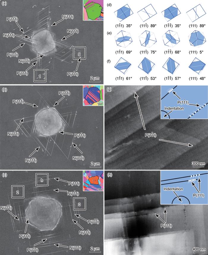
图1
80 mN压痕载荷下不同取向晶粒的二次电子(SE像)、反极图、相应滑移面示意图及电子通道衬度成像(ECCI)和示意图
Fig.1
Secondary electron (SE) images and inverse pore figures (insets) (a-c), corresponding schematics of slip planes (d-f), and electron channeling contrast imaging (ECCI) images and corresponding schematics (insets) (g, h) of grains with different orientations under 80 mN indentation load (P represents positive inclined, N represents negative inclined. Boxes 1, 2, and 3 in Figs.1a and c represent regions where double cross-slip exists. In Figs.1d-f, white lines represent the intersection line between the slip planes and the surface, which are the slip steps; bolded portions at the edges of the slip planes represent the angles closer to the sample surface, indicating the inclination angles between the slip planes and the surface)
(a, d, g) {101} grain (b, e) {111} grain (c, f, h) {001} grain
如图1a所示,{101}晶粒中存在沿4个{111}滑移面滑移所形成的滑移台阶。(
图2为80 mN压痕载荷下滑移台阶的局部放大SE像,其中图2a为图1a中方框1的局部放大图({101}晶粒),图2b和c分别为图1c中方框2和3的局部放大图({001}晶粒)。位错在2个不同滑移面上发生位错反应所形成的位错结会阻碍后续位错的滑移。此现象在SE像中表现为不同滑移面滑移台阶相交并且不再延伸。而图2中的情况则与上述情况不同,以图2a为例,P(
图2
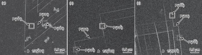
图2
80 mN压痕载荷下滑移台阶局部放大SE像
Fig.2
Partially enlarged SE images of slip steps in {101} grain (a) and {001} grain (b, c) under 80 mN indentation load (Dotted rectangles represent the slip steps formed by dislocations sliding along the slip plane before double cross-slip, solid rectangles represent the slip steps formed by dislocations sliding along the slip plane after double cross-slip.
(a) box 1 in Fig.1a (b) box 2 in Fig.1c (c) box 3 in Fig.1c
图3为不同压痕载荷下不同取向晶粒的SE像。当压痕载荷为5 mN时,{101}晶粒中只存在沿(
图3

图3
不同压痕载荷下各晶粒的SE像
Fig.3
SE images of {101} (a-c), {111} (d-f), and {001} (g-i) grains under indentation loads of 5 mN (a, d, g), 10 mN (b, e, h), and 20 mN (c, f, i) (Boxes 1-6 represent regions where dislocation interactions exist)
综上,VCoNi中熵合金中晶粒取向决定了纳米压痕诱导滑移系激活与开动的顺序,从而显著影响压坑周边滑移台阶的形貌。同一滑移面上的滑移台阶优先出现在正倾斜滑移面上。在{101}、{111}和{001}晶粒中,滑移台阶的整体形貌分别为蝴蝶状、嵌套三角形和十字形。
2.2 P-h 曲线
根据Hertz接触理论给出的载荷(P)与深度之间的关系[29],P的表达式如下:
式中,Er为折减模量,R为有效半径,h为对应载荷下的深度。因本工作使用的是球形压头,所以
根据Tuck等[30]的理论,塑性功(Wp)为:
式中,Pmax为最大载荷;hf为残余深度。
图4为不同压痕载荷下不同取向晶粒的P-h曲线和塑性功分布。如图4a~c所示,VCoNi中熵合金中各晶粒均经历弹性和初始塑性阶段。每个晶粒在不同压痕载荷下的弹性阶段均符合Hertz弹性接触理论曲线。同一晶粒在5和10 mN时的曲线较为吻合,说明其在5和10 mN压痕载荷下的原始位错状态相同。但当压痕载荷为20 mN时,P-h曲线存在差异,所需载荷较小,弹性阶段持续深度较浅;不同晶粒的P-h曲线中第1个pop-in对应的载荷取决于晶粒取向[31]。{101}、{111}和{001}晶粒在5 mN压痕载荷下,第1个pop-in对应的载荷分别为4.56、4.50和2.76 mN;在10 mN压痕载荷下,第1个pop-in对应的载荷分别为5.08、4.25和2.52 mN。第1个pop-in的出现表明材料发生了弹塑性转变,此时应力已达到位错形核的临界值或预先存在的位错发生滑移的临界剪切应力[32]。VCoNi的剪切模量为72 GPa[7],通过
图4
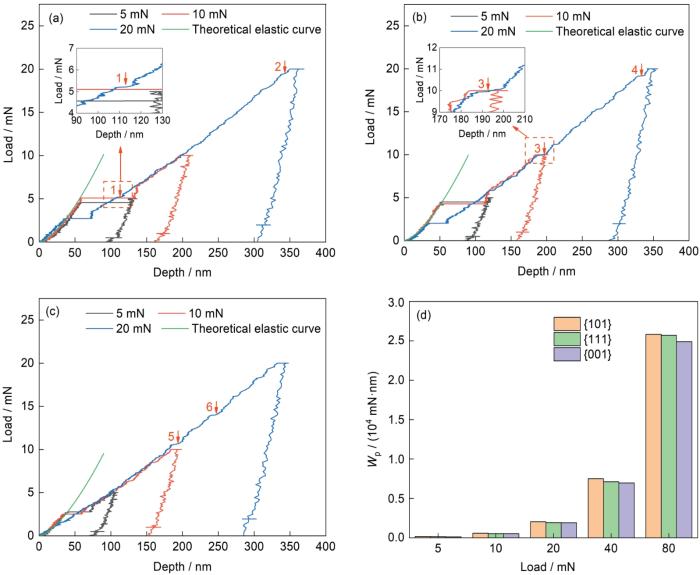
图4
不同压痕载荷下各晶粒的载荷-深度(P-h)曲线和塑性功分布
Fig.4
Load-displacement (P-h) curves of {101} (a), {111} (b), and {001} (c) grains and plastic work distributions (d) under different indentation loads (Insets in Figs.4a and b are enlarged images of pop-in. Red arrows and numbers together indicate the location of the subsequent pop-in. Wp—plastic work)
3 分析与讨论
VCoNi中熵合金中的滑移台阶和P-h曲线上后续出现的pop-in可归因于晶粒内部滑移系统的激活与位错运动。在运动过程中,不同滑移面的位错相遇时发生相互作用,即位错反应。由于晶粒取向、局部应力状态及滑移面的不同,参与反应的位错和位错反应的类型均存在显著差异。位错的相互作用会进一步影响塑性变形的过程,进而导致P-h曲线产生变化。因此,本节在明确不同晶粒内部位错间相互作用的基础上,进一步分析了后续pop-in与位错运动之间的关系。
3.1 位错间的相互作用
如图1所示,根据对应晶粒的Thompson四面体确定了位错所在滑移面,可结合fcc金属的塑性流动方向判断位错运动的方向,塑性流动方向分为垂直于滑移台阶的正向流动和平行于滑移台阶的侧向流动。塑性流动方向取决于滑移面的倾斜角,随着倾斜角的增加,塑性流动方向从正向转变为侧向,且过渡角为55°~58° [27]。本工作同样存在一个过渡角范围(53°~57°),当倾斜角大于57°时,塑性流动方向为侧向流动;当倾斜角小于53°时,塑性流动方向为正向流动。表1是fcc金属中全位错反应类型。全位错反应类型共有5种,其中4种可形成位错结,即Lomer、Hirth、Collinear和Glissile结[37]。根据位错所在滑移面和位错运动的方向,结合表1可进一步判断全位错反应的类型。
表1 fcc金属中全位错反应类型
Table 1
| Slip | ( | ( | ( | |||||||||||||
|---|---|---|---|---|---|---|---|---|---|---|---|---|---|---|---|---|
| plane | 1/2[110] | 1/2[ | 1/2[101] | 1/2[ | 1/2[ | 1/2[ | 1/2[011] | 1/2[ | 1/2[101] | 1/2[ | 1/2[011] | 1/2[110] | ||||
| ( | 1/2[110] | - | Copl | Copl | Lom | Hirth | Gliss | Lom | Hirth | Gliss | Gliss | Gliss | Coll | |||
| 1/2[ | Copl | - | Copl | Gliss | Gliss | Coll | Hirth | Lom | Gliss | Lom | Hirth | Gliss | ||||
| 1/2[101] | Copl | Copl | - | Hirth | Lom | Gliss | Gliss | Gliss | Coll | Hirth | Lom | Gliss | ||||
| (111) | 1/2[ | Lom | Gliss | Hirth | - | Copl | Copl | Lom | Gliss | Hirth | Coll | Gliss | Gliss | |||
| 1/2[ | Hirth | Gliss | Lom | Copl | - | Copl | Gliss | Coll | Gliss | Gliss | Lom | Hirth | ||||
| 1/2[ | Gliss | Coll | Gliss | Copl | Copl | - | Hirth | Gliss | Lom | Gliss | Hirth | Lom | ||||
| ( | 1/2[011] | Lom | Hirth | Gliss | Lom | Gliss | Hirth | - | Copl | Copl | Gliss | Coll | Gliss | |||
| 1/2[ | Hirth | Lom | Gliss | Gliss | Coll | Gliss | Copl | - | Copl | Lom | Gliss | Hirth | ||||
| 1/2[101] | Gliss | Gliss | Coll | Hirth | Gliss | Lom | Copl | Copl | - | Hirth | Gliss | Lom | ||||
| ( | 1/2[ | Gliss | Lom | Hirth | Coll | Gliss | Gliss | Gliss | Lom | Hirth | - | Copl | Copl | |||
| 1/2[011] | Gliss | Hirth | Lom | Gliss | Lom | Hirth | Coll | Gliss | Gliss | Copl | - | Copl | ||||
| 1/2[110] | Coll | Gliss | Gliss | Gliss | Hirth | Lom | Gliss | Hirth | Lom | Copl | Copl | - | ||||
图5为图3中方框区域的局部放大图和相应滑移面示意图。当压痕载荷为5 mN时,{101}晶粒中的位错先在(
图5
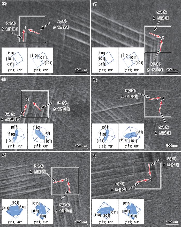
图5
5 mN压痕载荷下各晶粒滑移台阶的局部放大SE像和相应滑移面示意图
Fig.5
Partially enlarged SE images of slip steps and schematics of slip planes (insets) of {101} grain in Fig.3a (a, b), {111} grain in Fig.3d (c, d), and {001}grain in Fig.3g (e, f) (Red arrows in boxes indicate the direction of dislocation movement; 1-6 represent the junctions of dislocation interactions)
当压痕载荷为5 mN时,{111}晶粒上的位错在
当压痕载荷为5 mN时,{001}晶粒中位错在4个滑移面上形核、增殖并运动,滑移台阶整体形貌为四边形。如图5e所示,(111)滑移面与表面的倾斜角小于53°,塑性流动的方向为正向流动,而(
除了位错反应外,在图3中还可观察到不同滑移面的滑移台阶相互突破的现象。在{101}晶粒中,(
综上,不同取向晶粒在纳米压痕下激活的滑移系统不同,这也导致不同取向晶粒内的位错反应存在差异。{101}晶粒上位错反应形成Lomer-Cottrell位错锁和Glissile结;{111}晶粒上位错反应形成Collinear结和Lomer-Cottrell位错锁;{001}晶粒上位错反应形成Glissile结。此外,滑移台阶突破的现象与塑性流动有关,即与滑移面和表面之间的倾斜角有关。
3.2 P-h 曲线后续pop-in和位错运动之间的关联
位错运动和位错相互作用会导致P-h曲线产生变化。根据后续pop-in出现时所对应的载荷,并与不同载荷下滑移台阶形貌相结合,探究位错运动与其之间的关联。此外,在3.1节中讨论了位错间的相互作用,根据位错反应结果可进一步探讨其与后续pop-in之间的关联。
在20 mN压痕载荷下,各晶粒的P-h曲线中间歇性地出现较小的pop-in,与位错运动和相互作用存在关联。{101}晶粒在图4a中1号标记处出现的pop-in倾向于与(
{111}晶粒在图4b中3号标记处出现pop-in,这倾向于与(
综上,{101}晶粒后续pop-in与位错发生Glissile反应和Lomer-Cottrell位错锁解锁以及
4 结论
(1) VCoNi中熵合金中不同取向晶粒内部激活的滑移系不同,导致压痕形貌和演变过程存在差异。各晶粒中同一滑移面上的滑移台阶优先出现在正倾斜滑移面。{101}晶粒中(111)和
(2) 仅在{101}和{001}晶粒滑移台阶的边缘处观察到少量双交滑移的现象。{101}晶粒中位错先沿P(
(3) 不同取向晶粒激活的滑移系不同,导致位错反应类型不同并决定不同晶粒压痕的载荷-位移曲线中后续pop-in行为。{101}晶粒后续pop-in与(
参考文献
High-entropy alloys
[J].
Alloying has long been used to confer desirable properties to materials. Typically, it involves the addition of relatively small amounts of secondary elements to a primary element. For the past decade and a half, however, a new alloying strategy that involves the combination of multiple principal elements in high concentrations to create new materials called high-entropy alloys has been in vogue. The multi-dimensional compositional space that can be tackled with this approach is practically limitless, and only tiny regions have been investigated so far. Nevertheless, a few high-entropy alloys have already been shown to possess exceptional properties, exceeding those of conventional alloys, and other outstanding high-entropy alloys are likely to be discovered in the future. Here, we review recent progress in understanding the salient features of high-entropy alloys. Model alloys whose behaviour has been carefully investigated are highlighted and their fundamental properties and underlying elementary mechanisms discussed. We also address the vast compositional space that remains to be explored and outline fruitful ways to identify regions within this space where high-entropy alloys with potentially interesting properties may be lurking.
Tailoring heterogeneities in high-entropy alloys to promote strength-ductility synergy
[J].Conventional alloys are usually based on a single host metal. Recent high-entropy alloys (HEAs), in contrast, employ multiple principal elements. The strength of HEAs is considerably higher than traditional solid solutions, as the many constituents lead to a rugged energy landscape that increases the resistance to dislocation motion, which can also be retarded by other heterogeneities. The wide variety of nanostructured heterogeneities in HEAs, including those generated on the fly during tensile straining, also offer elevated strain-hardening capability that promotes uniform tensile ductility. Citing recent examples, this review explores the multiple levels of heterogeneities in multi-principal-element alloys that contribute to lattice friction and back stress hardening, as a general strategy towards strength-ductility synergy beyond current benchmark ranges.
Ultrastrong lightweight compositionally complex steels via dual-nanoprecipitation
[J].
A critical review of high entropy alloys and related concepts
[J].
Progress of cryogenic deformation and strengthening-toughening mechanisms of high-entropy alloys
[J].Owing to the multi-principal element and higher intrinsic configurational entropy, high-entropy alloys exhibit excellent mechanical and physicochemical performance, which has garnered extensive attention from researchers. By virtue of the excellent performances in terms of superior strength, ductility, toughness, impact resistance property, and adjustable phase stability, especially in cryogenic environments, high-entropy alloys have broad application prospects in fields such as deep-space exploration, low temperature superconducting, and the gas industry. In this paper, the deformation and strengthening-toughening mechanisms of high-entropy alloys are summarized by reviewing the cryogenic progress. Furthermore, the promising research directions of high-entropy alloys in cryogenic engineering application combined with the performance of traditional cryogenic materials are also presented.
高熵合金的低温塑性变形机制及强韧化研究进展
[J].高熵合金是由多种主要元素组成的新型金属材料,固有的多主元和构型熵高等特点,使其具备诸多优异的力学及物理化学性能,从而引起了研究人员的广泛关注。在低温工程应用方面,高熵合金优异的强塑性、良好的韧性和抗冲击能力、较高的相稳定性等特点使其在深空探测、低温超导、气体工业等领域极具应用前景。本文综述了高熵合金的低温研究进展,详细总结了高熵合金在低温环境的变形机制及强韧化机理,并结合传统低温工程材料的性能对比,展望了高熵合金未来低温工程应用的主要方向。
Strengthening-toughening mechanism and mechanical properties of span-scale heterostructure high-entropy alloy
[J].High-entropy alloys overcome the limitations posed by traditional alloys due to features such as high strength, toughness, high wear resistance, and corrosion resistance. These alloys are novel metallic materials with excellent application potential; however, typically an inverse relationship is observed between the strength and ductility of a metal, which includes high-entropy alloys. Therefore, the design and development of high entropy alloys with high strength and high ductility have become a limitation in current research. Recently, heterostructure design has achieved great success in strengthening and toughening traditional metallic materials. Heterostructured and high-entropy alloys has garnered much attention and research interest to realize the strength and toughness of high-entropy alloys with high strength and high ductility. This study reviews the existing design models for heterostructures from the heterostructure scale perspective. Furthermore, the effects of different heterostructures on the strengthening and toughening mechanism and mechanical properties were analyzed, and future microstructural designs with high strength and toughness were anticipated.
高熵合金跨尺度异构强韧化及其力学性能研究进展
[J].高熵合金突破了传统合金设计理念的桎梏,具有高强度、高硬度、高耐磨性及抗腐蚀性,是一种具有巨大发展前景的新型金属材料。然而,金属材料的强度与塑性之间存在倒置矛盾关系,高熵合金仍受困于这一难题。因此,设计开发兼具高强度与高塑性的高熵合金材料已成为目前研究热点与难点。近年来,异构设计理念在传统金属材料强韧化这一问题上得到发展,如何设计异构高熵合金以实现高熵合金强韧化,使合金兼具高强度与高塑性,引起了科研人员的重视。本文从异构显微组织尺度出发,综述了目前存在的异构显微结构设计方法,分析了不同异构组织对其强韧化机制及力学性能的影响,并对未来高强韧高熵合金显微结构设计进行了展望。
Ultrastrong medium-entropy single-phase alloys designed via severe lattice distortion
[J].
Structure motif of chemical short-range order in a medium-entropy alloy
[J].
Characterization of chemical short-range order in VCoNi medium-entropy alloy processed by spark plasma sintering
[J].
Effects of grain size and cryogenic temperature on the strain hardening behavior of VCoNi medium-entropy alloys
[J].
Effects of cryogenic temperature on tensile and impact properties in a medium-entropy VCoNi alloy
[J].Multi-principal element alloys usually exhibit outstanding strength and toughness at cryogenic temperatures, especially in CrMnFeCoNi and CrCoNi alloys. These remarkable cryogenic properties are attributed to the occurrence of deformation twins, and it is envisaged that a reduced stacking fault energy (SFE) transforms the deformation mechanisms into advantageous properties at cryogenic temperatures. A recently reported high-strength VCoNi alloy is expected to exhibit further notable cryogenic properties. However, no attempt has been made to investigate the cryogenic properties in detail as well as the underlying deformation mechanisms. Here, the effects of cryogenic temperature on the tensile and impact properties are investigated, and the underlying mechanisms determining those properties are revealed in terms of the temperature dependence of the yield strength and deformation mechanism. Both the strength and ductility were enhanced at 77 K compared to 298 K, while the Charpy impact toughness gradually decreased with temperature. The planar dislocation glides remained unchanged at 77 K in contrast to the CrMnFeCoNi and CrCoNi alloys resulting in a relatively constant and slightly increasing SFE as the temperature decreased, which is confirmed via ab initio simulations. However, the deformation localization near the grain boundaries at 298 K changed into a homogeneous distribution throughout the whole grains at 77 K, leading to a highly sustained strain hardening rate. The reduced impact toughness is directly related to the decreased plastic zone size, which is due to the reduced dislocation width and significant temperature dependence of the yield strength.
A strong and ductile medium-entropy alloy resists hydrogen embrittlement and corrosion
[J].Strong and ductile materials that have high resistance to corrosion and hydrogen embrittlement are rare and yet essential for realizing safety-critical energy infrastructures, hydrogen-based industries, and transportation solutions. Here we report how we reconcile these constraints in the form of a strong and ductile CoNiV medium-entropy alloy with face-centered cubic structure. It shows high resistance to hydrogen embrittlement at ambient temperature at a strain rate of 10 s, due to its low hydrogen diffusivity and the deformation twinning that impedes crack propagation. Moreover, a dense oxide film formed on the alloy's surface reduces the hydrogen uptake rate, and provides high corrosion resistance in dilute sulfuric acid with a corrosion current density below 7 μA cm. The combination of load carrying capacity and resistance to harsh environmental conditions may qualify this multi-component alloy as a potential candidate material for sustainable and safe infrastructures and devices.
In-situ observation of the initiation of plasticity by nucleation of prismatic dislocation loops
[J].The elastic-to-plastic transition during the deformation of a dislocation-free nanoscale volume is accompanied by displacement bursts associated with dislocation nucleation. The dislocations that nucleate during the so-called "pop-in" burst take the form of prismatic dislocation loops (PDLs) and exhibit characteristic burst-like emission and plastic recovery. Here, we report the in-situ transmission electron microscopy (TEM) observation of the initial plasticity ensued by burst-like emission of PDLs on nanoindentation of dislocation-free Au nanowires. The in-situ TEM nanoindentation showed that the nucleation and subsequent cross slip of shear loop(s) are the rate-limiting steps. As the indentation size increases, the cross slip of shear loop becomes favored, resulting in a transition from PDLs to open half-loops to helical dislocations. In the present case of nanoindentation of dislocation-free volumes, the PDLs glide out of the indentation stress field while spreading the plastic zone, as opposed to the underlying assumption of the Nix-Gao model.
Plasticity induced by nanoindentation in a CrCoNi medium-entropy alloy studied by accurate electron channeling contrast imaging revealing dislocation-low angle grain boundary interactions
[J].
Dislocation nucleation during nanoindentation in a body-centered cubic TiZrHfNb high-entropy alloy
[J].
Atomistic insights into the deformation mechanism of a CoCrNi medium entropy alloy under nanoindentation
[J].
Nanoindentation study on Ti-24Nb-4Zr-8Sn single crystals
[J].
Ti-24Nb-4Zr-8Sn合金单晶纳米压痕研究
[J].
The effect of crystal orientation on the stochastic behavior of dislocation nucleation and multiplication during nanoindentation
[J].
The effect of grain orientation on nanoindentation behavior of model austenitic alloy Fe-20Cr-25Ni
[J].
Orientation-dependent hardness and nanoindentation-induced deformation mechanisms of WC crystals
[J].
Orientation-dependent indentation modulus and yielding in a high Mn twinning-induced plasticity steel
[J].
Effect of crystal orientation on indentation-induced deformation behavior of zinc
[J].
The effect of hydrogen on the slip character of nickel
[J].
Study of the low stress plasticity in single-crystal MgO by nanoindentation and atomic force microscopy
[J].
Identifying slip systems around indentations in fcc metals
[J].
Analysis of dislocation mechanisms around indentations through slip step observations
[J].
Insight into indentation-induced plastic flow in austenitic stainless steel
[J].
Unraveling indentation-induced slip steps in austenitic stainless steel
[J].
On the application of the work-of-indentation approach to depth-sensing indentation experiments in coated systems
[J].
Mesoscale dislocation dynamics modeling of incipient plasticity under nanoindentation
[J].
Pop-in behavior and elastic-to-plastic transition of polycrystalline pure iron during sharp nanoindentation
[J].This study analyzes the elastic-to-plastic transition during nanoindentation of polycrystalline iron. We conduct nanoindentation (Berkovich indenter) experiments and electron backscatter diffraction analysis to investigate the initiation of plasticity by the appearance of the pop-in phenomenon in the loading curves. Numerous load-displacement curves are statistically analyzed to identify the occurrence of pop-ins. A first pop-in can result from plasticity initiation caused by homogeneous dislocation nucleation and requires shear stresses in the range of the theoretical strength of a defect-free iron crystal. The results also show that plasticity initiation in volumes with preexisting dislocations is significantly affected by small amounts of interstitially dissolved atoms (such as carbon) that are segregated into the stress fields of dislocations, impeding their mobility. Another strong influence on the pop-in behavior is grain boundaries, which can lead to large pop-ins at relatively high indentation loads. The pop-in behavior appears to be a statistical process affected by interstitial atoms, dislocation density, grain boundaries, and surface roughness. No effect of the crystallographic orientation on the pop-in behavior can be observed.
Incipient plasticity and deformation mechanisms in single-crystal Mg during spherical nanoindentation
[J].
Influence of pre-existing dislocations on the pop-in phenomenon during nanoindentation in MgO
[J].
Understanding pop-in phenomena in FeNi3 nanoindentation
[J].
Effect of crystal orientation on the nanoindentation deformation behavior of TiN coating based on molecular dynamics
[J].
Dislocation multiplication mechanisms-glissile junctions and their role on the plastic deformation at the microscale
[J].
Characterization of Lomer junctions based on the Lomer arm length distribution in dislocation networks
[J].
Molecular dynamics studies on formation of stacking fault tetrahedra in fcc metals
[J].
Direct observations of collinear dislocation interaction in a Fe-17.4Mn-1.50Al-0.29C (wt.%) austenitic steel under cyclic loading by in-situ electron channelling contrast imaging and cross-correlation electron backscatter diffraction
[J].
