


镍基高温合金具有优异的高温热稳定性、耐热腐蚀、抗蠕变、抗高温氧化等综合性能,在飞机发动机和各种工业燃气轮机的热端部件中发挥着关键作用[1]。变形高温合金可能析出多种析出相,如碳化物、硼化物、拓扑密堆(TCP)相等,这些析出相对合金的性能有较大的影响[1,2]。镍基变形高温合金中常添加难熔金属元素,这些难熔金属元素在提高合金承稳能力的同时,也会导致脆性TCP相的析出[3,4]。TCP相对高温合金的影响主要集中在2方面:一是TCP相的析出会消耗大量合金元素,影响基体的固溶强化效果[5,6];二是TCP相作为一类仅有四面体间隙的复杂密堆结构,排列十分紧密,表现出塑性低和脆性高的特点,易在蠕变过程中促进裂纹萌生及扩展,从而降低合金的蠕变强度[7~13]。
TCP相是有序分布的复杂金属间化合物,由2种或2种以上的非等径原子组成,小原子配位数为12,大原子的配位数可达到16[14,15]。科研人员[14~17]发现可以用主次层的方式表达TCP相,以TCP相中常见的μ相为例,沿着μ相的<11
作为μ相中最为常见的缺陷,基面层错的不同堆垛方式会形成不同结构的相,从而影响合金的力学性能,因此得到广泛的关注和研究[17,21,22,24~26]。Zhu和Ye[21]通过选区电子衍射(SAED)研究了铁基高温合金中的μ相,发现μ相中存在大量基面层错。Carvalho等[26]进一步研究了Co-W合金中μ相的缺陷结构,结合高分辨透射电子显微镜(HRTEM)实验与模拟发现,μ相基面上存在随机分布的亚结构孪晶(subunit cell twins)。Hiraga等[17]利用HRTEM研究了Co-Mo合金中的μ相,发现上述平行于基面的亚结构孪晶可形成较厚的孪晶片层。Cheng等[24]采用像差校正高角度环形暗场扫描透射电子显微镜(HAADF-STEM)对长期蠕变后镍基单晶高温合金中的μ相进行研究,同样发现了上述提到的亚结构孪晶,并将其命名为I型基面层错。对μ相而言,其平行四边形和矩形结构单元为其不可或缺的基本结构单元[18],而亚结构孪晶只是2个平行四边形结构单元的镜面对称,对称的结构单元中缺少完整的矩形结构单元。为了不引起歧义的同时准确表现亚结构孪晶厚度较小和关于矩形结构单元对称的特征,这里统称其为微对称结构。根据Gao等[25]的研究结果,μ相除I型基面层错外,还可能存在另外2种基面层错,分别形成C14结构和Zr4Al3相;Ma等[22]也发现相同的研究结果。结合Cheng等[24]对I型基面层错的定义,将形成C14结构和Zr4Al3相的2种基面层错分别称为II型和III型基面层错。与I型和III型基面层错相比,II型基面层错因更易形成常见的Laves相而倍受关注[18,23,24,27]。Ye等[18,28]、Gao等[25]和Liu等[29]报道了块体μ相与Laves相共生的现象。Chen等[30]研究了W-Fe复合材料中的μ相,Laves相比μ相更稳定,μ相有转化为Laves相的倾向。相的稳定性与相转变有一定关系,稳定性决定了相变的方向[31]。除此之外,μ相与Laves相结构单元的组成中都包括平行四边形结构单元,元素组成中包含Mo、Nb、W等难熔金属元素。μ相与Laves相之间的稳定性关系及结构和成分上的相似性为μ相转变为Laves相奠定了基础。Shi等[27]研究了马氏体铸铁中的μ相,发现随着μ相向Laves相转变,马氏体板条的粗化速率降低,铸铁的高温性能得以提高。
上述研究利用HRTEM等手段研究了μ相中的基面层错,然而除已发现的3种基面层错外,μ相中是否还可能存在其他类型的基面层错,这些基面层错在μ相转变为Laves相的过程中又发挥着怎样的作用等一系列问题尚未解决。与变形高温合金In718相比,本工作所用的GH4151镍基高温合金中含有更多的难熔金属元素,因此析出了较多的μ相。实验以GH4151晶界处析出的μ相为研究对象,采用电子背散射衍射(EBSD)、SAED、像差校正透射电子显微镜(TEM)等手段研究了μ相的晶体结构,解析了μ相中不同种类的基面层错,探讨了基面层错数量存在差异的原因,并揭示了μ相到C14结构的转变机制。
1 实验方法
实验材料为经真空感应熔炼铸锭+ 1120℃挤压的GH4151合金,挤压能消除铸锭中的微孔并改善力学性能,其化学成分(质量分数,%)为:Al 3.7,Nb 3.5,W 2.5,Ti 2.7,Mo 4.5,Co 14.9,Cr 8.8,C 0.08,B 0.015,Ni余量。合金的热处理制度是:1130℃固溶2 h后空冷 + 850℃时效4 h后空冷 + 780℃时效16 h后空冷。
对热处理后的样品进行拉伸实验,拉伸试样直径为3 mm、长16 mm。将拉伸试样在Zwick Z100高温电子万能试验机上夹紧,加热至650℃并保温10 min后再进行拉伸实验,应变速率3 × 10⁻⁴ s-1,拉断后空冷至室温。采用线切割将拉伸试样螺栓段切取直径6 μm、长400 μm样品,经过磨抛处理后,使用4 g CuSO4 + 10 mL HCl + 20 mL H2O腐蚀液进行化学抛光。采用Verios 460扫描电镜(SEM)获取EBSD像,并利用Channel 5软件处理EBSD数据。
利用TJ100-SE电化学双喷减薄仪对50 μm厚的小圆片双喷减薄以制备TEM/STEM样品,试剂为10%高氯酸+ 90%乙醇溶液(体积分数),电压为25 V,温度为-35~-15℃。使用JEM-2100 TEM获得明场像和SAED花样,运行电压200 kV,采用的分析软件为GMS-3。使用Tecnai F30场发射TEM获得低倍HAADF-STEM像和X射线能量色散谱(EDS),电压300 kV,分析软件为TIA。使用配备SuperX-EDS探测器的Themis Cubed G2像差校正TEM获得原子分辨率HAADF-STEM像和化学成分,电压300 kV,采用的分析软件为Velox。
第一性原理计算在密度泛函的框架下进行,使用的程序为Quantum ESPRESSO软件包[32]。Perdew-Burke-Ernzerhof (PBE)形式的广义梯度近似(GGA)[33]被用来描述电子之间的交换关联作用。电子占据的Fermi展宽宽度为1.3606 × 10⁻¹ eV,平面波的截断能为6.8028 × 10² eV。原子结构弛豫采用Broyden-Fletcher-Goldfarb-Shanno (BFGS)算法,结构弛豫的收敛条件为1.3606 × 10⁻² eV/atom。电子自洽收敛的收敛标准为1.3606 × 10-7 eV/cell。Brillion区采用Monkhorst-Pack k点采样,k点的采样精度是2π × 0.01。
2 实验结果
2.1 晶界上的析出相
图1
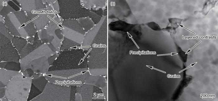
图1
时效镍基变形高温合金GH4151样品的EBSD和TEM像
Fig.1
EBSD (a) and TEM (b) images of the wrought Ni-based superalloy GH4151 sample after aging
2.2 晶界处 μ 相的结构
图2
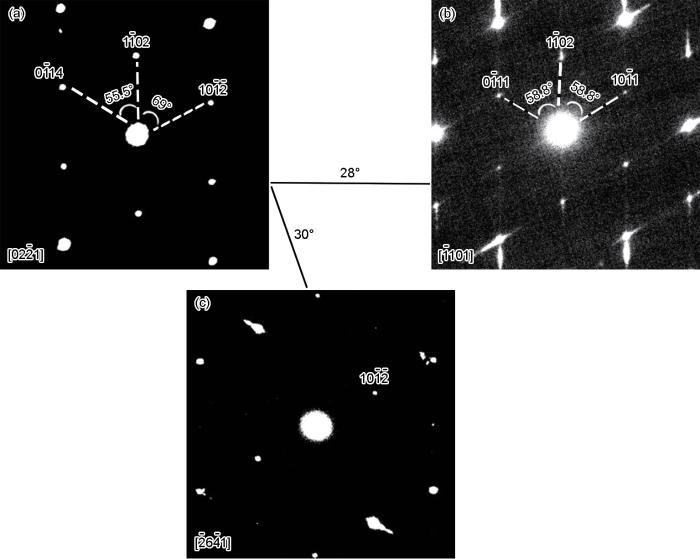
图2
μ相的系列选区电子衍射(SAED)花样,对应的晶带轴分别为[02
Fig.2
A series of selected area electron diffraction (SAED) patterns of μ phase obtained by tilting crystal. The corresponding crystal axes are [02
图3
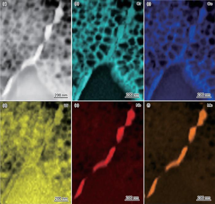
图3
μ相的低倍高角度环形暗场扫描透射电子显微镜(HAADF-STEM)像及EDS元素分布图
Fig.3
Low magnification high-angle annular dark-field scanning transmission electron microscopy (HAADF-STEM) image (a) and EDS element maps of μ phase (b-f)
图4
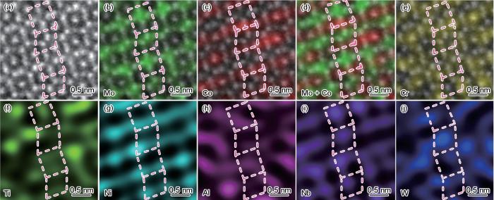
图4
μ相的原子级HAADF-STEM像及相应元素的面分布
Fig.4
Atomic-resolution HAADF-STEM image (a) and corresponding element maps (b-j) of μ phase (Figs.4b-e are the superpositions of HAADF-STEM images and corresponding element maps)
μ相[11
图5
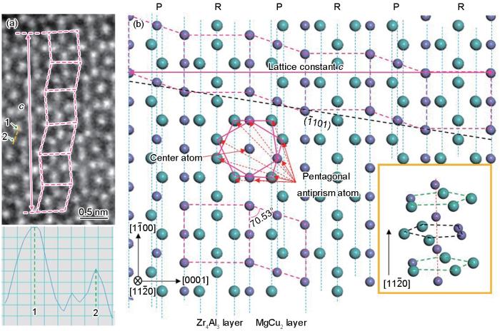
图5
μ相[11
Fig.5
Atomic-resolution HAADF-STEM image of μ phase viewed along [11
2.3 μ 相内的4类基面层错
图6
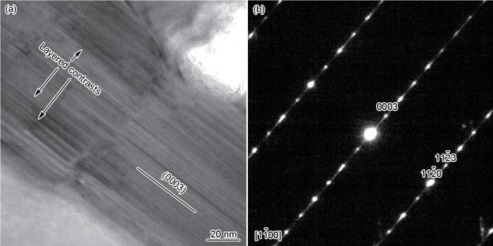
图6
μ相的TEM明场像及对应的SAED花样
Fig.6
Bright filed TEM image (a) and corresponding SAED pattern (b) of μ phase
图7
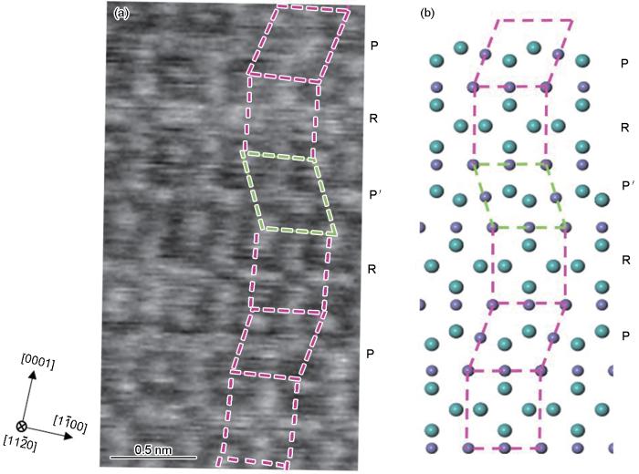
图7
I型基面层错[11
Fig.7
Atomic-resolution HAADF-STEM image of type I basal stacking fault (SF) of μ phase viewed along [11
图8
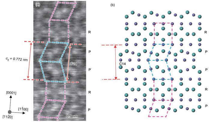
图8
μ相II型基面层错[11
Fig.8
Atomic-resolution HAADF-STEM image of type II basal SF of μ phase viewed along [11
图9
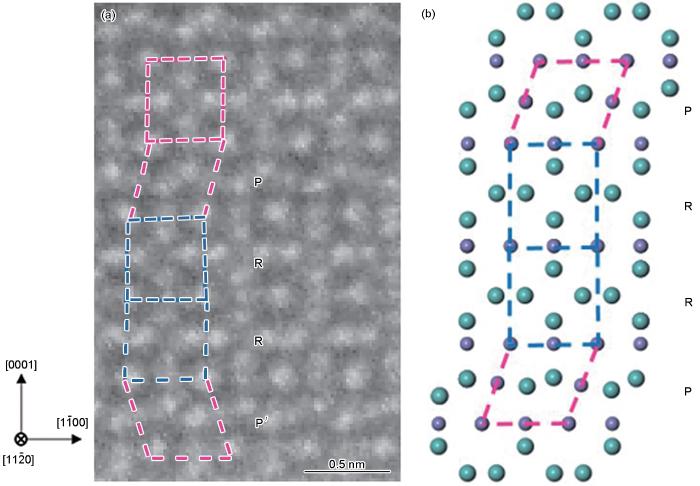
图9
μ相中III型基面层错[11
Fig.9
Atomic-resolution HAADF-STEM image of type III basal SFs of μ phase viewed along [11
图10
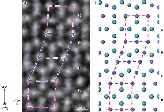
图10
μ相中IV型基面层错[11
Fig.10
Atomic-resolution HAADF-STEM image of type IV basal SF of μ phase viewed along [11
此外,在图8a中还观察到一种与I型基面层错不同的层错,层错内正向平行四边形结构单元P与反向平行四边形结构单元P′直接相连,构成C14结构,如图中浅蓝色格子所示;同时也出现了排列为P'RP的微对称结构。本文将这种层错称之为II型基面层错。在图8a一个完整的C14晶胞中测量得到C14结构的晶格常数为a2 = 0.473 nm,c2 = 0.772 nm。C14结构与μ相完全共格,满足[11
3 分析讨论
3.1 μ 相中基面层错的稳定性
本工作共观察到了4类基面层错,它们结构上的不同导致其在μ相中有不同的表现形式。对51个基面层错进一步统计,结果为I型基面层错4个,II型36个,III型4个,IV型7个。统计结果表明,4类基面层错中,II型基面层错最多,IV型基面层错次之,I型和III型基面层错最少。II型和IV型基面层错数目较多可能与它们都形成Laves相有关。尽管这2种基面层错都会形成Laves相,但II型基面层错(C14结构)的数量远多于IV型基面层错(C15结构)。本工作通过第一性原理计算C14和C15结构的形成能,分析了不同类型层错数目存在差异的原因。由于Laves相(C14、C15)在μ相内部生成,为准确搭建其原子模型,需要结合μ相的成分推断Laves相的组成元素。结合元素分析的结果,Laves相中大原子以Mo为主,小原子以Cr和Co为代表,因此Laves相应为Cr2Mo或Co2Mo。因为无论Cr2Mo还是Co2Mo都可能形成C14和C15 2种结构,所以本工作分别以Cr2Mo和Co2Mo 2种元素组成搭建了C14和C15 2种结构,共4种模型。采用这4种模型进行第一性原理计算,计算结果如表1所示。结果表明,无论结构如何,Co2Mo的形成能都低于Cr2Mo,由此推断Laves相的组成为Co2Mo;与C15结构相比,C14结构的Co2Mo形成能更低,表明μ相更倾向于形成Co2Mo C14结构。此结论也可以从Co原子与C14相的结构相似性中加以验证。Co单质和C14结构均为密排六方P63/mmc空间群,Co原子能较好地融入C14结构的空间排列中,这种结构具有一定的稳定性。而C15结构为Fd
表1 C14和C15结构的形成能 (meV·atom-1)
Table 1
| Structure | C14 | C15 |
|---|---|---|
| Cr2Mo | 109 | 92 |
| Co2Mo | -128 | -103 |
3.2 μ 相转变为C14结构的机制
研究[27,30]表明,μ相是一种亚稳相,而Laves相是稳态相,μ相有转变为Laves相的倾向。从3.1节来看,尽管同为Laves相,但C14结构的稳定性高于C15结构,因此μ相能转化为C14结构。不同厚度C14结构的原子级HAADF-STEM像(图8a和11)展现了μ相转变到C14结构的具体过程,该过程包含C14结构形核和长大2个阶段。在形核阶段,完整μ相中一层平行四边形结构单元反向,同时相邻的一层矩形结构单元缺失,即生成一层II型基面层错,最终形成一个晶胞厚度(c2)的C14结构,如图8a所示。形核完成后,在C14结构上端再生成一次II型基面层错就可以使C14结构生长一层至厚度1.5c2 (图11a)。在厚度1.5c2的基础上,只需要在C14结构下端缺失一层矩形结构单元可以使C14结构再生长一层达到2c2的厚度(图11b)。在此基础上,先后在C14结构上端缺失矩形结构单元和在下端生成II型基面层错就可以使厚度增加至3c2。因此,C14结构可通过两端交替生成一层II型基面层错(图8a~11a)和缺失一层矩形结构单元(图11a和b)的方式进行生长。值得注意的是,图11a中C14结构上端若缺失一层矩形结构单元也可形成厚度2c2的C14结构,此时C14结构排列为PP′PP′ (由上到下),与图11b中P′PP′P的排列关于(1
图11
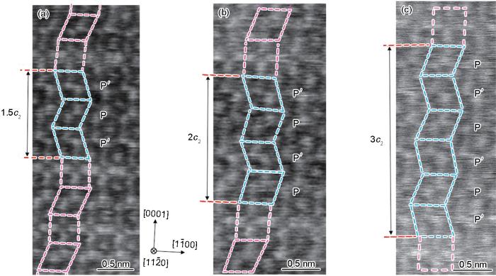
图11
不同厚度C14结构[11
(a) 1.5c2 (b) 2c2 (c) 3c2
Fig.11
Atomic-resolution HAADF-STEM images of C14 structure with different thicknesses viewed along [11
4 结论
(1) GH4151镍基高温合金晶界处析出μ相。μ相属于菱方R
(2) μ相中存在4类基面层错。I型基面层错相当于完整μ相的一层平行四边形结构单元反向,形成2个微对称结构;II型基面层错相当于在I型基面层错基础上缺失一层矩形结构单元,形成C14结构和微对称结构;III型基面层错为完整μ相缺失一层平行四边形结构单元并形成完整Zr4Al3相;IV型基面层错为μ相缺失一层矩形结构单元并形成C15结构。
(3) II型和IV型基面层错都会导致Laves相的形成,统计发现前者的数目高于后者,第一性原理计算表明II型基面层错(C14结构)的高出现频率与其低形成能有关。
参考文献
Tetrahedrally close-packed phases in superalloys: New phases and domain structures observed by high-resolution electron microscopy
[J].
Influence of TCP phase and its morphology on creep properties of single crystal nickel-based superalloys
[J].
Influence of topologically closed packed phase formation on creep rupture life of directionally solidified nickel-base superalloys
[J].
Stacking faults in the Co7W6 isomorph of the μ phase
[J].
Dislocations in complex materials
[J].
Deformation of metals and alloys by dislocations gliding between well-separated slip planes is a well-understood process, but most crystal structures do not possess such simple geometric arrangements. Examples are the Laves phases, the most common class of intermetallic compounds and exist with ordered cubic, hexagonal, and rhombohedral structures. These compounds are usually brittle at low temperatures, and transformation from one structure to another is slow. On the basis of geometric and energetic considerations, a dislocation-based mechanism consisting of two shears in different directions on adjacent atomic planes has been used to explain both deformation and phase transformations in this class of materials. We report direct observations made by Z-contrast atomic resolution microscopy of stacking faults and dislocation cores in the Laves phase Cr2Hf. These results show that this complex dislocation scheme does indeed operate in this material. Knowledge gained of the dislocation core structure will enable improved understanding of deformation mechanisms and phase transformation kinetics in this and other complex structures.
On the role of μ phase during high temperature creep of a second generation directionally solidified superalloy
[J].
Shear deformation determined by short-range configuration of atoms in topologically close-packed crystal
[J].
Undulating slip in Laves phase and implications for deformation in brittle materials
[J].
Shuffle and glide mechanisms of prismatic dislocations in a hexagonal C14-type Laves-phase intermetallic compound
[J].
Role of crystal defects on brittleness of C15 Cr2Nb Laves phase
[J].
Complex alloy structures regarded as sphere packings. I. Definitions and basic principles
[J].
Complex alloy structures regarded as sphere packings. II. Analysis and classification of representative structures
[J].
Topologically close-packed structures of transition metal alloys
[J].
Intermetallic compounds of the μ- and P-phases of Co7Mo6 studied by 1 MV electron microscopy
[J].
Domain structures of tetrahedrally close-packed phases with juxtaposed pentagonal antiprisms I. Structure description and HREM images of the C14 Laves and μ phases
[J].
Plastic-deformation mechanism in complex solids
[J].In simple crystalline materials, plastic deformation mostly takes place by the movement of dislocations. Although the underlying mechanisms in these materials are well explored, in complex metallic alloys--crystalline solids containing up to thousands of atoms per unit cell--the defects and deformation mechanisms remain essentially unknown. Owing to the large lattice parameters of these materials, extended dislocation concepts are required. We investigated a typical complex metallic alloy with 156 atoms per unit cell using atomic-resolution aberration-corrected transmission electron microscopy. We found a highly complex deformation mechanism, based on the movement of a dislocation core mediating strain and separate escort defects. On deformation, the escort defects move along with the dislocation core and locally transform the material structure for the latter. This mechanism implies the coordinated movement of hundreds of atoms per elementary glide step, and nevertheless can be described by simple rearrangement of basic structural subunits.
Novel metadislocation variants in orthorhombic Al-Pd-Fe
[J].
On the microstructure and its diffraction anomaly of the μ phase in superalloys
[J].
Atomic arrangement and formation of planar defects in the μ phase of Ni-base single crystal superalloys
[J].
Domain structures of tetrahedrally close-packed phases with juxtaposed pentagonal antiprisms III. Domain boundary structures in the μ phase
[J].
Atomic configurations of planar defects in μ phase in Ni-based superalloys
[J].
In situ TEM investigation on the precipitation behavior of μ phase in Ni-base single crystal superalloys
[J].
HRTEM study of Co7W6 and its typical defect structure
[J].
A high N and W heat-resistant martensitic cast steel with balanced tensile strength and creep resistance achieved by Laves and μ intermetallics
[J].
Domain structures of tetrahedrally close-packed phases with juxtaposed pentagonal antiprisms II. Domain boundary structures of the CI4 Laves phase
[J].
Intergrowth structure of Laves within μ phases in Co-Al-W base superalloy
[J].
Additive manufacturing of W-Fe composites using laser metal deposition: microstructure, phase transformation, and mechanical properties
[J].
QUANTUM ESPRESSO: A modular and open-source software project for quantum simulations of materials
[J].
Generalized gradient approximation made simple
[J].
