


激光熔覆Ni60A等涂层因具有良好的耐腐蚀性能、抗氧化性及耐磨性而受到学者的广泛关注[7~10],其中Asghar等[8]通过激光熔覆技术制备的Ni60涂层,由γ-Ni过饱和固溶体及一些原位析出的硬质相(如:Cr及B的碳化物)组成,涂层平均硬度达到948 HV,耐磨性能显著提升。然而,随着熔覆速率的增加,基体的稀释率和热影响区(heat-affected zone,HAZ)范围随之减小,基体热累积量降低[11]。当熔覆速率从0.6 m/min提高至76.6 m/min,涂层的HAZ宽度从约400 μm降至50 μm左右,同时熔覆界面的宽度也从约150 μm减至3 μm左右[7]。随着基体稀释率和热累积量的降低,Ni60A熔覆界面位置开始出现裂纹和气孔缺陷[12],在界面应力[13]的作用下诱导低塑性脆化裂纹扩展[14]。因此,界面位置成为最薄弱环节。
TiC和TiB2等陶瓷相具有硬度高、耐磨性好和热稳定性良好等优点[15,16],与Ni的润湿性良好[17,18]。向Ni60A涂层中引入上述陶瓷颗粒相的原位反应生成剂,以期生成TiC和TiB2颗粒相细化晶粒,同时利用原位反应放热延缓EHLA的超常冷却速率,有望抑制Ni60A涂层的低塑性脆化裂纹形成,从而获得高质量耐磨涂层。本工作将EHLA技术与直接反应合成(direct reaction synthesis,DRS)技术相耦合,成功制备了均匀的Ti(C, B)/Ni60A复合涂层。利用涂层内反应体系放热,有效提高了EHLA对基材的稀释率,缓解了熔覆界面的应力突变,结合涂层磨损机理研究,为EHLA原位制备金属基陶瓷复合涂层探索了一种技术可行性。
1 实验方法
1.1 熔覆层制备
EHLA基体选用直径150 mm、长300 mm的调质态H13钢棒,表面加工至粗糙度Ra = 0.2 μm后用C2H5OH清洗。EHLA用预合金粉末由真空气雾化法(vacuum induction melting gas atomization,VIGA)制备的Ni60A粉末、等离子旋转电极法(plasma rotary electrode process,PREP)制备的Ti185粉末和碳热还原法获得的B4C颗粒组成,并按80%Ni60A + 20%(Ti185 + B4C) (质量分数)配比,其中Ti与B4C按照3∶1 (摩尔比)进行计算。采用XQM-60型立式行星球磨机对预合金粉末进行低速混合球磨2 h。采用激光功率4.4 kW、周向线速度5 m/min、轴向进给量1.6 mm/r、送粉速率28 g/min和Ar气保护流量7 L/min的EHLA工艺,在室温条件下对高速旋转的H13棒材表面进行超高速激光熔覆,分别制备出轴向熔覆长度250 mm、厚度约0.6 mm的Ti(C, B)/Ni60A复合涂层和纯Ni60A涂层(作为对比分析试样)。
1.2 微观组织表征
利用线切割在熔覆棒料长度1/2位置处截取涂层截面金相试样,试样尺寸(长15 mm × 高10 mm × 宽8 mm)与文献[13]保持一致,依次经400、800和1200号水砂纸研磨并抛光,用质量分数为10%FeCl3 + 4%HNO3的酒精溶液侵蚀3~5 s。利用XHVT-1000Z型Vickers硬度计在金相试样上测试涂层浅表区Vickers硬度。利用JSM-7200F型扫描电镜(SEM)观察预合金粉末形貌和金相试样上涂层的界面特征,利用Oxford-Max型能谱仪(EDS)分析预合金粉末的成分和熔覆界面的元素面分布。对金相试样振动抛光4 h后,利用EDAX Velocity Super型电子背散射衍射(EBSD)探头分析涂层的相分布和微取向差,扫描步长0.1 μm。利用聚焦离子束(focused ion beam,FIB)分别沿Ti(C, B)/Ni60A复合涂层磨损表面和纯Ni60A涂层磨损表面的法向切取带有浅表磨损信息的薄片,尺寸均为8 μm × 8 μm × 50 nm,采用Titan Cube 80-300型双球差透射电镜(double spherical aberration-transmission electron microscopy,DSA-TEM,200 kV)观察2种涂层磨损前沿微区的形貌,对Ti(C, B)/Ni60A复合涂层内的陶瓷相作进一步物相鉴定,并采用仪器自带的EDS分析其元素面分布。
1.3 纳米压痕测试
式中,H为Berkovich压痕获得的硬度;Er为等效模量,由纳米压痕设备直接读取;We为弹性功;Wt为塑性功,由纳米压痕设备直接计算获取。
Giannakopoulos和Suresh[19]考虑了应变硬化对压痕凸起变形和真实接触面积的影响,利用三维模型建立了真实接触面积A与最大压入深度hmax之间的关系:
联立
式中,α为Berkovich压头边界与材料表面的夹角,取值24.7°。
1.4 磨损测试
采用MDW-02型高速往复摩擦磨损试验机[20],分别对EHLA耦合DRS制备的Ti(C, B)/Ni60A复合涂层和EHLA制备的纯Ni60A涂层进行表面磨损实验,对磨副选取360号SiC砂纸。测试过程参照ASTM G 133—02执行,采用水润滑,轴向加载力20 N,往复行程30 mm,实验频率2 Hz,测试每30 min更换砂纸,累计测试90 min。3个试样为一组,获得平均摩擦系数后测量平均磨损失重。
2 实验结果
2.1 粉体特征
图1

表1
预合金粉末的制备方法、粒径尺寸及
Table 1
| Point | Material | Preparation method | Particle | Mass fraction / % | |||||||||||
|---|---|---|---|---|---|---|---|---|---|---|---|---|---|---|---|
| size / μm | Ni | Cr | Mo | Si | Fe | Nb | Ti | V | Zr | Al | C | B | |||
| 1 | Ni60A | VIGA | 15-53 | 69.77 | 16.60 | - | 4.40 | 5.54 | - | - | - | - | - | 0.88 | 2.81 |
| 2 | TA185 | PREP | ≤ 15 | - | - | - | - | 6.51 | - | 82.59 | 8.85 | - | 2.05 | - | - |
| 3 | B4C | Carbothermal reduction | 1-5 | - | - | - | - | - | - | 0.10 | 0.05 | 0.05 | 0.80 | 32.9 | 66.1 |
2.2 熔覆界面区形貌
图2
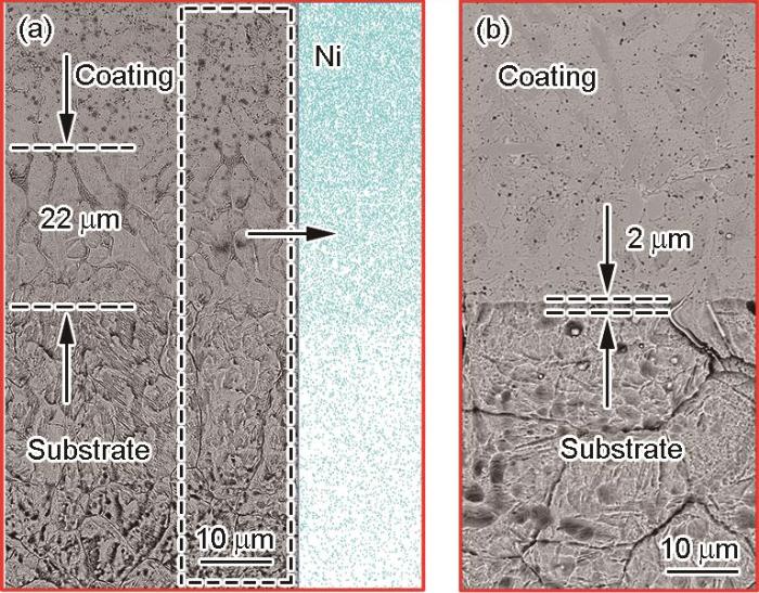
图2
Ti(C, B)/Ni60A复合涂层界面区形貌和Ni元素分布及Ni60A涂层界面区形貌
Fig.2
Interfacial zone morphologies of Ti(C, B)/ Ni60A composite coating with EDS distribution of Ni (a) and Ni60A coating (b)
2.3 涂层形貌
根据SEM的背散射电子(BSE)像衬度差异和EDS分析,EHLA制备Ni60A涂层(图3a)的γ-Ni基体中分布了大量条状Cr-C系碳化物、块状Cr-B系硼化物、以及少量的非稳态针状Cr-B-Ni系硼化物,涂层总体呈现较高的硬度特征。而EHLA耦合DRS原位制备的Ti(C, B)/Ni60A复合涂层,生长区(图3b)组织形貌呈现柱状晶特征,浅表区(图3c)组织形貌呈现等轴晶特征,且均可见弥散分布的点状增强相,起到了明显细化晶粒的作用。对于固定熔覆速率的涂层,其凝固参数G / R (其中,G为温度梯度,R为熔体凝固速率)从涂层底部至顶部逐渐减小[5,7,21,22]。相比传统激光熔覆,EHLA具有更高的熔覆速率,R又与熔覆速率正相关,叠加激光与粉末相互作用时间减少,粉末的热累积量降低,G随之进一步降低,由此会在涂层浅表区产生更多细小的等轴晶。相比EHLA涂层,EHLA耦合DRS原位制备的放热体系涂层的R同比降低,叠加反应体系放热提高了瞬态熔池峰值温度,导致G增大,因此G / R的增加不利于EHLA耦合DRS原位制备Ti(C, B)/Ni60A复合涂层等轴晶的形成,但从质点形核动力学角度分析,熔池中DRS原位反应的产物可为熔池凝固后期提供大量的形核点,最终促成了图3c所示等轴晶形貌。
图3

图3
Ni60A涂层的背散射电子(BSE)像、Ti(C, B)/Ni60A复合涂层柱状晶和等轴晶的BSE像及对应的EBSD和核平均取向差(kernel average misorientation,KAM)图
Fig.3
Backscattered electron (BSE) morphologies of Ni60A coating (a); columnar crystals (b) and equiaxial crystals (c) of Ti(C, B)/Ni60A composite coating and the corresponding EBSD (red area—TiCB phase, green area—Ti3B4 phase, and yellow area—TiCrB4 phase) (d) and kernel average misorientation (KAM) map (e)
从图3d所示EBSD分析结果可见,涂层浅表区的颗粒相显著增加,其中红色标记为TiCB相,少量绿色标记和微量黄色标记分别为Ti3B4相和TiCrB4相。由于涂层中Ni60A与原位合成的Ti(C, B)颗粒相间存在密度差异,Ti(C, B)颗粒相在高速旋转离心力作用下沿涂层厚度方向形成了浓度梯度分布。涂层浅表区Ti(C, B)颗粒相越多,涂层凝固后期的形核过冷度越低,细化了图3c中平均粒径达8~10 μm的等轴晶。进一步地,通过分析核平均取向差(kernel average misorientation,KAM)图量化了晶粒之间和晶粒内部局部取向变化。由图3e可见,在涂层浅表区等轴晶内/晶界上存在着不超过5°的错配角,这在一定程度上也反映了涂层浅表区的应变分布情况,因此有必要对熔覆涂层开展界面应力分析。
2.4 涂层横截面应力分布
由图4基于G&S能量法计算的残余应力分布图可见,Ni60A涂层和Ti(C, B)/Ni60A复合涂层在熔覆区至HAZ范围内均呈现明显的残余拉应力。其中,Ni60A涂层在熔覆界面位置的残余拉应力达到峰值430 MPa后,在HAZ区呈现陡降趋势;而Ti(C, B)/Ni60A复合涂层的残余拉应力峰值出现在熔覆界面靠近涂层一侧,约330 MPa,并随后呈现较缓和的降低走势。
图4

图4
超高速激光熔覆涂层截面的残余应力分布
Fig.4
Residual stress distribution on the cross section of coating by ultra-high speed laser cladding
2.5 涂层表面磨损
EHLA耦合DRS原位制备的Ti(C, B)/Ni60A复合涂层表面平均磨损率为0.007 g/h,平均摩擦系数为0.122,磨损形貌呈现磨粒磨损特征(图5a),磨损前该位置Vickers硬度仅达到360~400 HV0.2。Ni60A涂层表面平均磨损率为0.005 g/h,平均摩擦系数为0.158,略高于Ti(C, B)/Ni60A复合涂层,磨损形貌呈现磨粒磨损+黏着磨损特征(图5b),而磨损前期该位置的Vickers硬度却高达880~920 HV0.2。相同实验条件下对标具有磨粒磨损特征的H13热作模具钢磨损表面(图5c),其平均磨损率和平均摩擦系数分别进一步提高到0.011 g/h和0.22,这说明EHLA耦合DRS原位制备的Ti(C, B)/Ni60A复合涂层表面具有显著的耐磨减摩特点。
图5

图5
Ti(C, B)/Ni60A复合涂层、Ni60A涂层和H13钢的表面磨损形貌
Fig.5
Surface wear morphologies of Ti(C, B)/Ni60A composite coating (a), Ni60A coating (b), and H13 steel (c)
3 分析讨论
相比较EHLA制备的Ni60A涂层,EHLA耦合DRS原位制备Ti(C, B)/Ni60A复合涂层熔覆界面区的残余应力呈缓降分布,这主要归因于
式中,
计算结果显示:TiC的反应标准Gibbs自由能
图6为基于FIB制样的Ti(C, B)/Ni60A复合涂层DSA-TEM像及其内部原位反应颗粒相分析。图6a所示的FIB样品完整保留了涂层的磨损浅表区信息。进一步观察图6b所示的磨损浅表区可知,Ti(C, B)/Ni60A复合涂层磨损浅表区的微观组织形貌自上而下呈现了3个明显特征区域,即:0~180 nm范围内的超细化等轴晶区,180~600 nm范围内的细晶粒变形区,以及600 nm以上的原始Ti(C, B)/Ni60A复合涂层组织区。因磨损试验机轴向加载和摩擦过程中的区域热累积[26],在涂层浅表区下600 nm范围内发生了有别于原始涂层组织的晶粒细化过程,该细化的晶粒多呈现扁平状形貌,具有一定的方向性,这主要是由于摩擦热-力两相耦合作用下该范围内的原始晶粒发生了动态再结晶[27] +实时塑性变形过程[28]。动态再结晶原理[29]认为:位错在低层错能的材料内部通过滑移/攀移,促使晶粒形核和长大,从而消除形变基体中的位错及亚晶界等形变缺陷。进一步观察磨损浅表区下0~180 nm范围内的超细化等轴晶区,该区域晶粒尺寸范围为20~50 nm,其形成原因为:原位生成的Ti(C, B)颗粒相对Ni60A基体起到了减摩及区域支撑作用,SiC砂纸对Ni60A基体浅表区的犁削作用显著降低,反而带动Ni60A基体浅表区累积发生摩擦热塑性变形,最终促成0~180 nm范围内的表面磨损浅表区在强表面滑擦塑性流变-热-力三场耦合作用下,发生区域超塑性变形,进而导致该微区超细化等轴晶的形成。
图6

图6
基于聚焦离子束(FIB)制样的Ti(C, B)/Ni60A复合涂层双球差透射电镜(DSA-TEM)像及其内部原位反应颗粒相分析
Fig.6
Double spherical aberration-transmission electron microscopy (DSA-TEM) images of Ti(C, B)/Ni60A composite coating based on focused ion beam (FIB) fabricated sample and in situ reactive particle phase analyses
(a, b) DSA-TEM (a) and local magnified (b) images
(c) corresponding high magnified image of Fig.6b and in situ reactive particle phase analyses
(c1-c6) EDS mappings of B (c1), Ti (c2), Ni (c3), C (c4), Cr (c5), and Al (c6)
(d1, d2) SAED patterns of corresponding positions shown in Fig.6c
此外,由于SiC硬度(2400~2800 HV)略低于Ti(C, B)硬度(TiC:2600~3000 HV,TiB2:2500~3300 HV),2者在对磨初期会存在SiC颗粒的脱离,在对磨面上形成三体磨料磨损,犁削涂层基体,使得Ti(C, B)硬质颗粒相在三体磨损过程中微凸起于基体[30];随着后期摩擦系数的稳定,Ti(C, B)硬质颗粒相与SiC砂纸构成稳定支撑后形成摩擦接触体,对涂层基体产生“屏蔽”和“疲劳碾压”作用,进一步促成上述涂层磨损浅表层的强表面滑擦塑性流变。
图7a为EHLA制备的Ni60A涂层磨损浅表区DSA-TEM像。由于缺少原位反应合成的Ti(C, B)颗粒相对涂层磨损浅表区的支撑作用,Ni60A涂层浅表区未见上述的超细化等轴晶区,取而代之的是明显的细晶粒变形区。对该区浅表位置进行选晶高分辨图像分析,并采用Fourier逆变换随机分析了图7b所示4个晶界位置的位错分布,如图7c~f所示。其中,图7c和d可见大量位错呈有序排列,这说明晶界周围存在动态回复机制,同时也佐证了所述浅表细晶粒变形区的形成是在犁削磨损塑性变形+摩擦热诱导的再结晶共同作用下动态完成的,所形成的动态再结晶晶粒在后续持续性摩擦碾压过程中进一步形成了如图7a所示的细晶粒变形态结构。
图7
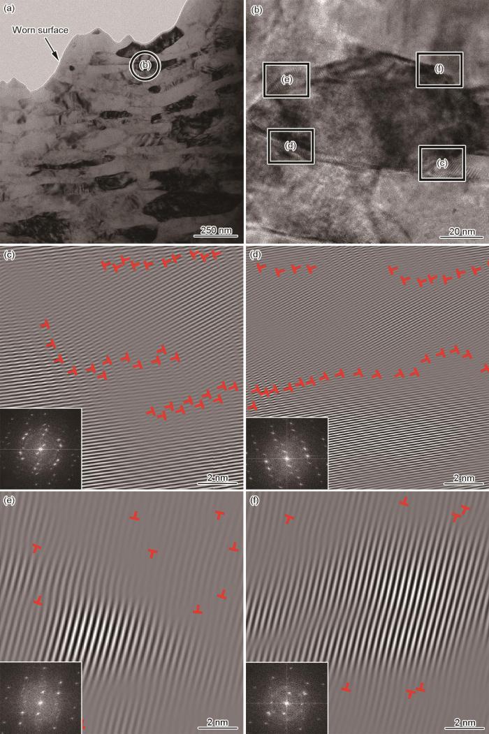
图7
基于FIB制样的Ni60A涂层磨损浅表区DSA-TEM像,高分辨像及其选定区的快速Fourier逆变换与快速Fourier变换
Fig.7
DSA-TEM image of the worn surface of Ni60A coating based on FIB sample (a), selected high-resolution image (b), and corresponding inverse fast Fourier transforms and fast Fourier transforms (insets) of specific regions in Fig.7b (c-f)
Ti(C, B)/Ni60A复合涂层的浅表区Vickers硬度明显低于Ni60A涂层。分析认为:一方面,原始混合的预合金粉体中由于B4C粒径和密度相对较小,在空间送粉激光熔覆过程中不可避免地发生部分损耗,由此变相造成混合粉体进入熔池的Ti含量偏高,并促进Ti与Ni60A成分中的C、B等亲和元素发生原位反应,导致Ni60A涂层基体的硬度降低;另一方面,
4 结论
(1) 将EHLA技术与DRS技术耦合,向预合金混合粉体中引入原位反应剂,成功制备了Ti(C, B)/Ni60A复合涂层。复合涂层界面受到原位反应影响放出约670 kJ的Joule热,界面宽度达到22 μm,是EHLA制备Ni60A涂层界面(2 μm)的11倍,有效促进了界面熔合,降低了界面区的应力梯度,起到缓解界面应力失配的目的。
(2) EHLA制备Ni60A涂层的γ-Ni基体中分布有大量Cr-C系碳化物、Cr-B系硼化物以及少量Cr-B-Ni系硼化物,涂层表面Vickers硬度偏高,为880~920 HV0.2。而EHLA耦合DRS原位制备的Ti(C, B)/Ni60A复合涂层表面Vickers硬度偏低,为360~400 HV0.2,基体中弥散分布的点状TiCB和Ti3B4等增强相为涂层凝固后期提供了大量形核质点,促使涂层浅表区等轴晶组织转变。
(3) 弥散分布的点状TiCB和Ti3B4等增强相在涂层浅表磨损过程中微凸起于Ti(C, B)/Ni60A复合涂层基体,对涂层浅表区起到了减摩耐磨和支撑作用;同时在磨损过程中涂层浅表基体受到“疲劳碾压”作用,促成强表面滑擦塑性流变-热-力三场耦合效果,在磨损浅表区0~180 nm范围内形成了晶粒尺寸为20~50 nm的超细化等轴晶,亦提升了磨损浅表区基体强化作用。
参考文献
Influence of WC content on microstructure of WC/Ni60A laser cladding layer
[J].
WC含量对WC/Ni60A激光熔覆层微观组织的影响
[J].
Failure analysis of a die casting die made of H13 steel
[J].
H13钢压铸模具的失效分析
[J].
Investigations on ultra-high-speed laser material deposition as alternative for hard chrome plating and thermal spraying
[J].
Alternative with a future: High-speed laser metal deposition replaces hard chrome plating
[J].
High speed laser cladding of an iron based alloy developed for hard chrome replacement
[J].
Comparison on microstructure and properties of stainless steel layer formed by extreme high-speed and conventional laser melting deposition
[J].
A comparative study on microstructure and properties of traditional laser cladding and high-speed laser cladding of Ni45 alloy coatings
[J].
Enhanced tribological properties of LA43M magnesium alloy by Ni60 coating via ultra-high-speed laser cladding
[J].
Microstructure and corrosion resistance of Ni/stainless steel surfacing layer deposited via high-speed laser cladding
[J].
快速激光熔覆Ni/不锈钢堆焊层组织及耐蚀性能研究
[J].
Effects of laser scanning speed on microstructure, microhardness, and corrosion behavior of laser cladding Ni45 coatings
[J].
Effect of metallurgical behavior on microstructure and properties of FeCrMoMn coatings prepared by high-speed laser cladding
[J].
Study on crack and porosity control methods of laser cladding Ni60A alloy coating
[D].
Ni60A合金激光熔覆裂纹气孔控制方法研究
[D].
M2 coating prepared by ultra-high speed laser cladding: Microstructure and interfacial residual stress
[J].
Study on crack suppression of Ni60B coating by laser cladding
[D].
激光熔覆Ni60B涂层裂纹抑制研究
[D].
Influences of TiC impurities on dry-sliding wear of polycrystalline ceramic
[J].
Properties of B4C-TiB2 ceramics prepared by spark plasma sintering
[J].
Improvement of high temperature oxidation resistance of additively manufactured TiC/inconel 625 nanocomposites by laser shock peening treatment
[J].
Effect of surface morphology and microstructure on the hot corrosion behavior of TiC/IN625 coatings prepared by extreme high-speed laser cladding
[J].
Determination of elastoplastic properties by instrumented sharp indentation
[J].
(Ti, Nb)(C, B)/IN625 in-situ reactive coating prepared by ultra-high-speed laser cladding: Interfacial characterization, residual stress and surface wear mechanisms
[J].
Research status and development of ultra-high speed laser cladding
[J].
超高速激光熔覆技术研究现状及发展趋势
[J].
Comparative study of stainless steel AISI 431 coatings prepared by extreme-high-speed and conventional laser cladding
[J].
The effect of electric field and pressure on the synthesis and consolidation of materials: A review of the spark plasma sintering method
[J].
Diffusion bonding mechanism and properties of the joints between gradient cermets and metals bonding by the FAPAS process
[D].
梯度金属陶瓷与金属电场辅助扩散连接的机理及界面性能研究
[D].
TiC-TiB2-Ni/TiAl/Ti gradient functionally materials synthesized by in-situ sunthesis via field-activated and pressure-assisted synthesis
[J].
电场激活压力辅助法原位合成TiC-TiB2-Ni/TiAl/Ti功能梯度材料
[J].
Thermoelastic rotating contact of an FGM coating with temperature-dependent and arbitrary varying properties
[J].
Impact of friction stir welding (FSW) process parameters on thermal modeling and heat generation of aluminum alloy joints
[J].
A review of friction stir joining of SiCp/Al composites
[J].
Three-body abrasive wear behavior of iron matrix composite reinforced with cemented carbide particles
[J].
硬质合金颗粒增强铁基复合材料的三体磨料磨损性能
[J].
Graded materials of (TiB2)pNi with nickel substrate prepared by field-activated pressure-assisted synthesis process
[J]. J.
