烧结是通过加热使粉末颗粒结合成块状材料的过程。烧结过程可以分为3类:晶体材料烧结、非晶材料烧结(即黏性烧结)以及液相烧结[1 ] ,其中黏性烧结和液相烧结均涉及液相。烧结过程中液相能够润湿固体颗粒并提供毛细力,从而加快烧结颗粒的演化,改善烧结组织和物理性能[2 ,3 ] 。表面张力作用下引起的颗粒变形和凝聚是晶体材料固相烧结的主要驱动力[4 ] ,经过多年的发展,该理论已经比较成熟。当烧结温度高于晶体熔点时,材料可被当作黏性不可压缩Newton流体,表面张力与材料黏性引起颗粒变形和凝聚,该过程称为黏性烧结过程[5 ,6 ] 。黏性烧结过程的数值模拟涉及烧结扩散理论与Navier-Stokes流体方程的耦合问题,相关模型的建立仍然具有很大的挑战。
长期以来,国内外学者对黏性烧结的数值模拟开展了一些研究[7 ~12 ] 。黏性烧结模拟最早由Frenkel[7 ] 提出,该模型认为:在表面能作用下,2个点接触的黏性球体颗粒合并过程中半径不变,最终合并为一个大的球体颗粒。目前描述黏性烧结的主要方法有:有限元法[8 ] 、边界积分法[9 ] 、格子Boltzmann法(lattice Boltzmann method,LBM)[10 ] 、Monte Carlo方法[11 ] 、相场方法[12 ] 等。其中,基于Ginzburg-Landau[13 ] 理论的相场方法对界面做了弥散化处理,可以有效追踪界面的动态演变过程;而且相场方法同时考虑了烧结的热力学因素和动力学过程。因此,相场方法可以更好地模拟和再现黏性烧结过程中颗粒内部的演化过程。
近年来,相场方法已被成功利用于模拟固相烧结过程中界面和气孔形貌演化的研究中[14 ~18 ] 。Wang[15 ] 考虑了刚体平移和旋转、边界迁移的颗粒长大以及各种扩散机制,对相场方程的对流项进行了修正。Zhang和Liao[17 ] 构造激光烧结的相场模型,模拟了金属材料的固态激光烧结过程,与扫描电镜实验结果吻合较好。Kumar等[18 ] 研究了固体非等大颗粒的烧结演化,将烧结过程总结为烧结颈形成、颗粒边界缓慢合并迁移、颗粒边界快速迁移3个子过程。然而,上述相场模型均集中在晶体材料的固相烧结领域,因此开发能准确描述液相烧结过程的相场模型非常重要。液相烧结过程涉及流场,因此液相烧结模型需要考虑更复杂的物理过程[19 ~21 ] 。Tegze等[19 ] 利用相场方法模拟了亚稳态液体和玻璃相的分离过程,讨论了由液滴Brown运动引起的凝固过程、蒸发冷凝过程、扩散耦合过程中液滴尺寸分布情况。Soligo等[20 ] 考虑了气泡在静止流体中上升和层流剪切流的相互作用,修正了相场公式求解湍流的多相流问题。高英俊等[21 ] 利用晶体相场模型研究了环境温度达到固-液共存温度时,在外加应变作用下的小角度晶界、位错的湮灭过程以及外加应力与预熔化区域之间的关系。上述模型为黏性烧结相场模型的开发提供了一些思路,但完整准确地描述黏性烧结的形貌演变和流场等工作需要耦合Cahn-Hilliard方程与Navier-Stokes方程并进行准确求解。
本工作建立了黏性烧结相场模型,分析了烧结颗粒形貌及其速度场、压强场的演化过程,得到了烧结颈和收缩率的变化曲线,研究了迁移率对演化速度的影响;最后模拟了多颗粒体系的烧结过程,并与实验结果进行了对比。
1 相场模型
基于相场理论,建立Cahn-Hilliard方程与Navier-Stokes方程耦合的相场模型。引入保守型相场变量c 来建立相场模型,气相中c 为0,液相中c 为1,气/液界面处c 的值连续变化。
1.1 Cahn-Hilliard 方程
本工作烧结相场模型的总自由能泛函数(F )采用以下形式[12 ] :
F = ∫ Ω [ f ( c ) + 1 2 κ c | ∇ c | 2 ] d Ω (1)
式中,积分号内部表示系统的自由能密度。其中,κ c 为梯度能量参数;1 2 κ c | ∇ c | 2 f (c )是体自由能密度函数,表示保守场变量的双势阱函数,它的2个极小值分别为气、液两相中保守场变量;Ω 为该积分点处的空间坐标。
本工作中体自由能密度f (c ) = 0.25Ac 2 (1-c )2 [12 ] ,其中A 为局部自由能参数。参数A 和κc 的表达式分别为[12 ] :
A = 3 σ 2 2 ε (2)
κ c = 3 ε σ 2 2 (3)
式中,σ 为两相接触界面表面张力系数;ε 为相场变量扩散界面的宽度。本工作中选取扩散界面宽度为Δx ,Δx 为离散化后一个网格的宽度。
相场模型中c 的演化方向遵从总自由能减小的方向,得出模型中的Cahn-Hilliard方程。在传统Cahn-Hilliard方程的基础上,本工作考虑流体对流引起的相场变量的迁移,加入守恒形式的对流项方程变为:
∂ c ∂ t + ∇ ⋅ ( V c ) = ∇ ⋅ ( M ∇ δ F δ c ) (4)
式中,M 为迁移率,本工作采用常量形式[12 ] ; V δ F δ c
δ F δ c = d f ( c ) d c - κ c Δ c (5)
d f ( c ) d c = 1 2 A c ( 1 - c ) ( 1 - 2 c ) (6)
1.2 Navier-Stokes 方程
烧结过程中涉及流体,考虑流体速度变化的影响,在相场模型中加入Navier-Stokes方程对速度场进行模拟。
计算系统的流场可假设为不可压缩流场、流体为Newton流体、烧结过程为等温过程,质量守恒与动量守恒方程为:
∂ ρ ∂ t + ∇ ⋅ ( ρ V ) = 0 (7)
ρ ∂ V ∂ t + ρ V ∇ ⋅ V = - ∇ p + ∇ ⋅ τ + s (8)
式中,ρ 为密度,场内点的密度利用线性插值得到ρ =ρ liquid c + ρ gas (1 - c ),其中ρ gas 、ρ liquid 分别为气、液两相密度。 式(7)在不可压缩条件下,密度不随空间和时间进行变化,可简化为:
∇ ⋅ ( V ) = 0 (9)
式(8)左边第一项为速度对时间变化项,第二项为对流项,由于流体为不可压缩流体,因此可以使用普通型 V V VV ω × V ω 为角速度)等,由于本工作使用迎风型差分格式,因此使用普通型的对流量表达较为快捷方便;等式右边为体积微元被施加的应力: τ p 为压强项, s [23 ] :
s = δ F δ c ∇ c (10)
由于流体为Newton流体,满足Newton黏性定律剪切应力正比于速度梯度的条件,可表示为:
τ = ∇ ⋅ ( μ ( ∇ V + ∇ V T ) ) (11)
式中,μ 为动力黏性系数,场内具体点的动力黏性系数利用线性插值得到,μ = μ liquid c + μ gas (1 - c ),μ liquid 、μ gas 分别为气、液两相的动力黏性系数。
对于黏性烧结需求解式(1)、(8)和(9)组成的方程组,下文介绍非线性方程组中离散格式与计算方式。
2 离散格式与计算方法
本工作采用差分法对该过程进行数值模拟,具体步骤如下:首先,进行无量纲化,缩小计算不同项的量级差距,减小截断误差对计算结果的影响;之后,进行离散化,时间离散完成后,在固定时间步内进行空间离散;最后,求解速度与相场变量的预估值,通过投影法采用预估值计算压强与速度修正量,再进行速度场变量修正与相场变量耦合,求解完成推进时间步。
2.1 模型的无量纲化
在多颗粒黏性烧结模拟过程中,为了便于数值求解,需对方程中的变量和常量进行无量纲化处理:先选取一组参考物理量,然后用模型中变量除以参考量得到无量纲量。其中基本物理参数如表1 [12 ,23 ] 所示,本工作选取的参考量为参考能量密度ε * 、参考时间t * 、参考长度l * 。将各参量代入演化方程,进行无量纲化后各参数可表示为:M ˜ = t * ε * ( l * ) 2 M A ˜ = A ε * κ ˜ c = κ c ε * ( l * ) 2 ρ ˜ = ( l * ) 2 ε * ( t * ) 2 ρ V ˜ = t * l * V μ ˜ = t * ε * μ ∇ ˜ = l * ∇ p ˜ = p ε * t ˜ = t t * M ˜ A ˜ κ ˜ c ρ ˜ V ˜ μ ˜ ∇ ˜ p ˜ t ˜
∂ c ∂ t ˜ + ∇ ˜ ⋅ ( V ˜ c ) =
∇ ˜ ⋅ ( M ˜ ∇ ˜ ( 1 2 A ˜ c ( 1 - c ) ( 1 - 2 c ) - κ ˜ c Δ ˜ c ) ) (12)
∇ ˜ ⋅ ( V ˜ ) = 0 (13)
ρ ˜ ∂ V ˜ ∂ t ˜ + ρ ˜ V ˜ ∇ ˜ ⋅ V ˜ =
- ∇ ˜ p ˜ + ∇ ˜ ⋅ ( μ ˜ ( c ) ( ∇ ˜ V ˜ + ∇ ˜ V ˜ T ) ) + δ F ˜ δ c ∇ ˜ c (14)
2.2 时间离散格式
显格式的时间离散并不能满足黏性烧结相场模拟的需要,颗粒界面处初始相场变量值、密度和动力黏性系数均发生突变从而引起方程解的间断。本工作使用提高精度后的显格式,即二阶的Runge-Kutta (R-K)法。R-K法的离散格式如下:先将Cahn-Hilliard方程与Navier-Stokes方程进行移项,有∂ V ˜ ∂ t ˜ = f ˜ ( V ˜ ) ∂ c ∂ t ˜ = g ˜ ( c )
V ˜ ( 1 ) = V ˜ n + Δ t ˜ f ˜ ( V ˜ n ) (15)
V ˜ n + 1 = 1 2 V ˜ n + 1 2 ( V ˜ ( 1 ) + Δ t ˜ f ˜ ( V ˜ ( 1 ) ) ) (16)
式中,上标n 和n + 1分别代表第n 个和第n + 1个时间步的取值,上标(1)代表n 到n + 1时间步之间预测步的取值,Δ t ˜
c ( 1 ) = c n + Δ t ˜ g ˜ ( c n ) (17)
c n + 1 = 1 2 c n + 1 2 ( c ( 1 ) + Δ t ˜ g ˜ ( c ( 1 ) ) ) (18)
在时间步内,对于f ˜ ( V ˜ ) g ˜ ( c )的计算方式主要依靠空间离散进行求解。
2.3 空间离散格式
在空间离散上,对于不可压缩流体使用一般的直角均匀网格,可能会出现速度棋盘式分布得出奇异解,而采用半交错网格能够避免这种情况[24 ] 。
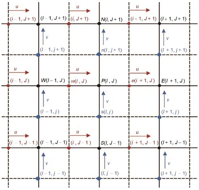
本工作采用的半交错网格[24 ] 如图1 所示。图中u 代表x 方向的速度分量,v 代表y 方向的速度分量。可以看出,矢量和标量位于不同的网格上进行处理:标量包括μ 、ρ 以及c ,均位于实线交点处的网格,即黑色标点P 、N 、W 、E 、S ,其坐标对应于(I, J ),称为一号坐标系;u 位于水平实线与垂直虚线的交点处的网格,即红色标点e 、w ,其坐标对应于(i, J ),称为二号坐标系;v 位于竖直实线与水平虚线的交点处的网格,即蓝色标点n 、s ,其坐标对应于(I, j ),称为三号坐标系。此时u 相当于在标量网格向右移动了半个网格,v 相当于在标量网格向上移动了半个网格。该种方式可以消除棋盘式分布的速度情况,半交错网格对于不同网格上的量进行映射,在计算本网格上点值时更加方便。对于一号坐标系与二号坐标系之间的映射如下式所示:
图1
图1
半交错网格示意图
Fig.1
Schematic illustration of staggered mesh (u is the velocity component in the x direction, and v is the velocity component in the y direction. The red points are used for the discrete format of u , and the blue points are used for the discrete format of v . The black points are used for the discrete format of scalars, including viscosity μ , density ρ and phase field c )
u ˜ ( I , J ) = u ˜ ( i + 1 , J ) + u ˜ ( i , J ) 2 (19)
一号坐标与三号坐标系之间的映射同理。二号坐标系与三号坐标系的映射公式如下所示:
v ˜ ( i , J ) = v ˜ ( I , j - 1 ) + v ˜ ( I + 1 , j - 1 ) + v ˜ ( I , j ) + v ˜ ( I + 1 , j ) 4 (20)
不同坐标系下的映射完成后对方程进行离散处理,下文介绍在半交错网格下对Cahn-Hilliard方程和Navier-Stokes方程的离散方式。
2.3.1 Navier-Stokes方程差分格式
首先对Navier-Stokes方程中的对流项进行差分,对流项为等 式(14)左边第二项ρ ˜ V ˜ ∇ ˜ ⋅ V ˜ x 方向表示为( u ˜ u ˜ x ' + v ˜ u ˜ y ' ) y 方向表示为( u ˜ v ˜ x ' + v ˜ v ˜ y ' )
( u ˜ u ˜ x ' + v ˜ u ˜ y ' ) ( i , J ) = u ˜ ( i , J ) u ˜ x ( i , J ) ' + v ˜ ( i , J ) u ˜ y ( i , J ) ' = u ˜ ( i , J ) u ˜ x ( i , J ) ' + v ˜ ( I , j - 1 ) + v ˜ ( I + 1 , j - 1 ) + v ˜ ( I , j ) + v ˜ ( I + 1 , j ) 4 u ˜ y ( i , J ) ' (21)
( u ˜ v ˜ x ' + v ˜ v ˜ y ' ) ( I , j ) = v ˜ ( I , j ) v ˜ y ( I , j ) ' + u ˜ ( I , j ) v ˜ x ( I , j ) ' = v ˜ ( I , j ) v ˜ y ( I , j ) ' + u ˜ ( i - 1 , J ) + u ˜ ( i - 1 , J + 1 ) + u ˜ ( i , J ) + u ˜ ( i , J + 1 ) 4 v ˜ x ( I , j ) ' (22)
式中,u ˜ x ' u ˜ y ' u 在x、y 方向的导数,v ˜ x ' v ˜ y ' v 在x、y 方向的导数,根据u ( i , J ) 、v ( i , J ) 、u ( I , j ) 、v ( I , j ) 的正负选用相应方向的迎风格式进行差分化。对于其中偏导数,根据速度方向进行迎风方向的一阶差分即:
u ˜ x ( i , J ) ' = u ˜ ( i , J ) - u ˜ ( i - 1 , J ) 2 ( u ˜ ( i , J ) > 0 ) u ˜ ( i + 1 , J ) - u ˜ ( i , J ) 2 ( o t h e r w i s e ) (23)
u ˜ y ( i , J ) ' = u ˜ ( i , J ) - u ˜ ( i , J - 1 ) 2 ( v ˜ ( I , j - 1 ) + v ˜ ( I + 1 , j - 1 ) + v ˜ ( I , j ) + v ˜ ( I + 1 , j ) > 0 ) u ˜ ( i , J + 1 ) - u ˜ ( i , J ) 2 ( o t h e r w i s e ) (24)
将Navier-Stokes方程中的扩散项差分化,速度Laplace算子使用五点差分法求解。半交错网格中,速度点上的动力黏性系数μ ˜ ( c )
2.3.2 Cahn-Hilliard方程差分格式
Cahn-Hilliard方程中自由能变分项∇ ˜ ( M ˜ ∇ ˜ δ F ˜ δ c ) ∇ ˜ ⋅ ( V ˜ c )
∇ ˜ ⋅ ( V ˜ c ) = ∂ ( u ˜ ( i + 1 , J ) + u ˜ ( i , J ) 2 c ( I , J ) ) ∂ x ˜ + ∂ ( v ˜ ( I , j + 1 ) + v ˜ ( I , j ) 2 c ( I , J ) ) ∂ y ˜ (25)
式(25)中,若 u ˜ ( i + 1 , J ) + u ˜ ( i , J ) 2 ≥ 0
∂ ( u ˜ ( i + 1 , J ) + u ˜ ( i , J ) 2 c ( I , J ) ) ∂ x ˜ = u ˜ ( i + 1 , J ) + u ˜ ( i , J ) 2 c ( I , J ) - u ˜ ( i , J ) + u ˜ ( i - 1 , J ) 2 c ( I - 1 , J ) (26)
若 u ˜ ( i + 1 , J ) + u ˜ ( i , J ) 2 < 0
∂ ( u ˜ ( i + 1 , J ) + u ˜ ( i , J ) 2 c ( I , J ) ) ∂ x = u ˜ ( i + 2 , J ) + u ˜ ( i + 1 , J ) 2 c ( I + 1 , J ) - u ˜ ( i + 1 , J ) + u ˜ ( i , J ) 2 c ( I , J ) (27)
若 v ˜ ( I , j + 1 ) + v ˜ ( I , j ) 2 ≥ 0
∂ ( v ˜ ( I , j + 1 ) + v ˜ ( I , j ) 2 c ( I , J ) ) ∂ y ˜ = v ˜ ( I , j + 1 ) + v ˜ ( I , j ) 2 c ( I , J ) - v ˜ ( I , j ) + v ˜ ( I , j - 1 ) 2 c ( I , J - 1 ) (28)
若 v ˜ ( I , j + 1 ) + v ˜ ( I , j ) 2 < 0
∂ ( v ˜ ( I , j + 1 ) + v ˜ ( I , j ) 2 c ( I , J ) ) ∂ y ˜ = v ˜ ( I , j + 2 ) + v ˜ ( I , j + 1 ) 2 c ( I , J + 1 ) - v ˜ ( I , j + 1 ) + v ˜ ( I , j ) 2 c ( I , J ) (29)
其余项中Laplace算子采用五点差分法,梯度和散度使用中心差分法进行计算。
2.3.3 投影法求解压强
根据时间离散与空间离散求解出速度与相场变量预测步的值并非精确解,上面的求解并未考虑 式(13)对速度的限制,求解出预测步的速度无法满足 式(13)散度为0的条件,因此需要考虑压强对速度进行修正,求解出满足 式(13)限制条件的速度场。
不可压缩流体的流场求解压强并没有直接的计算表达形式,只能通过动量守恒方程和质量守恒方程联立求得压强场的形式。本工作使用投影法,将u 和v 分别进行求解,暂不考虑压强项的影响得出预测步的x 方向速度u *
ρ ˜ ( u ˜ * - u ˜ n d t ˜ + ( u ˜ u ˜ x + v ˜ u ˜ y ) n ) = ∇ ˜ ⋅ ( μ ˜ ( c ) ( ∇ ˜ u ˜ ) ) + s ˜ x n (30)
式中,s ˜ x s ˜ x 方向分量。将离散的动量方程代入连续性方程得到压力方程,二维有限差分格式下经过计算整理得出压强的Poisson方程:
- ∇ ˜ ⋅ ( ∇ ˜ p ˜ n + 1 ρ ˜ n ) = - 1 Δ t ˜ ∇ ˜ ⋅ u ˜ * (31)
ρ ˜ n ( 1 Δ t ˜ ∇ ˜ ⋅ u ˜ n + 1 - 1 Δ t ˜ ∇ ˜ ⋅ u ˜ * ) = - ∇ ˜ ⋅ p ˜ n + 1 (32)
对压强与速度的值进行迭代计算,直到满足散度为0的条件即可输出,对y 方向同理可以得到v 的值。
3 结果与讨论
3.1 烧结过程的形貌演化
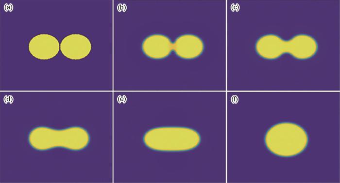
利用构造的黏性烧结模型对等大双颗粒的烧结过程进行模拟。模拟区域差分网格尺寸为256 × 256,采用周期性边界条件,模拟颗粒的形貌、速度以及压强在整个区域的演化过程。等大双圆形颗粒烧结过程的形貌演变如图2 所示。可以看出,随着模拟时间的延长,由最初等大两圆形颗粒逐渐演化为表面能更低的单个圆形颗粒。黏性烧结演化过程的驱动力主要为曲率梯度驱动。曲率梯度驱动是由烧结颈处曲率和液体颗粒曲率的差值引起的传质。最初阶段为液体颗粒黏弹性接触,此时界面间附着力使其进一步演化。接下来在液体颗粒接触点形成凹凸结合的马鞍状烧结颈,在晶体颗粒曲率梯度的作用下液体原子从曲率较小的液体边界处移动到曲率较大的烧结颈处,原子的沉积和迁移使得烧结颈半径增大。随着烧结的进行,烧结颈的曲率逐渐减小,曲率梯度逐渐减小,驱动力减小导致物质通量下降,反应过程变得缓慢。该相场模拟结果与文献[25 ]黏弹性接触结果类似。
图2
图2
等大双圆形颗粒烧结过程的形貌演化
(a) 0 step (b) 2 × 10⁴ step (c) 2 × 10⁵ step (d) 1.2 × 10⁶ step (e) 6 × 10⁶ step (f) 4 × 10⁷ step
Fig.2
Microstructure evolutions of the two equal circle grains during sintering
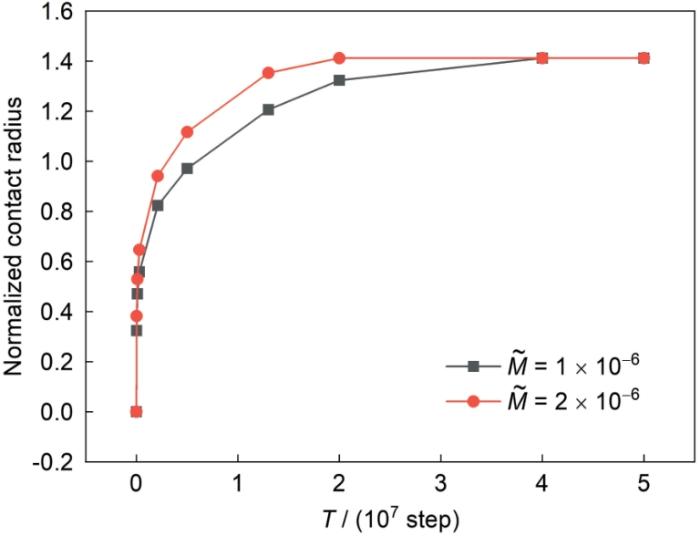
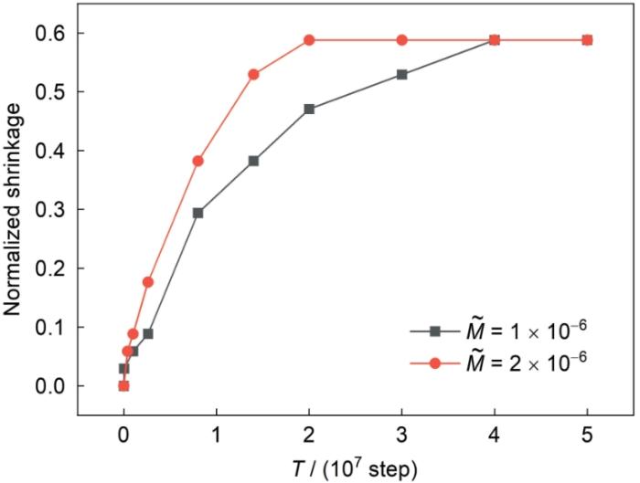
3.2 颈球比与收缩率的变化
图3 和4 分别为不同迁移率下的颈球比和收缩率随演化时间步的变化关系。其中,T 表示时间步;颈球比为X / D (其中,X 为t 时刻烧结颈的长度,D 为t 时刻的粒径);收缩率为(2D - L ) / D (其中,L 为双颗粒演化过程中的长度)。可以看出,颈球比和收缩率变化趋势一致,烧结开始阶段变化较快,随着时间的延长变得缓慢。由于开始时不平衡,驱动力较大,在2 × 10⁷ 时间步后,变化速度明显变慢。随着迁移率的增大,整体演化速率加快,整体演化趋势不变,且最终稳定的值并不发生改变。进一步分析发现,模拟后期的颈球比为1.411 (接近2 ) ,而收缩率为0.588 (接近2 - 2 d d t ∫ c d Ω = 0 [7 ] ;且颈球比随时间的变化为( X D ) 2 ∝ t 26 ]中颈球比随时间变化函数相似。
图3
图3
不同迁移率下颈球比随时间的变化关系
Fig.3
Normalized contact radius growth curves under different mobilities (M ˜ T —time step)
图4
图4
不同迁移率下收缩率随时间的变化关系
Fig.4
Normalized shrinkage vs time step curves under different mobilities
3.3 烧结过程速度场与压强场的变化
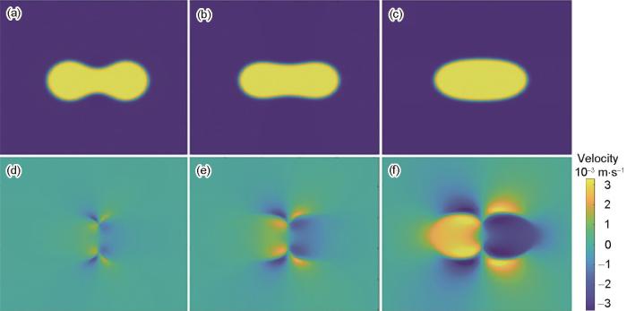
图5 为烧结过程中沿水平方向(即x 方向)的速度分量u 的分布。可以看出,u 非零的部分主要分布在液体内部和气/液边界处。在黏性烧结模拟过程中,液相颗粒内部的速度形成主要是由相的迁移引起的。烧结过程中烧结颈处,曲率梯度最大,导致该处质量迁移最大,因此表现为图5 中颜色最深处,水平方向速率最大。速度演化过程中,速度开始在气液接触界面产生,逐渐传递到液体颗粒内部。双颗粒中液体分子水平速度方向均沿着颗粒合并的方向。
图5
图5
颗粒形貌演变与对应的水平方向的速度场分布
Fig.5
Microstructure evolutions (a-c) and the corresponding horizontal velocity distributions (d-f) of the two equal circle grains (Blue represents negative values indicating the direction of velocity to the left; yellow is a positive value representing the right direction of velocity, ranging from -3.3 × 10⁻³ m/s to 3.3 × 10⁻³ m/s in the velocity cloud map) (a, d) 6 × 10⁵ step (b, e) 2 × 10⁶ step (c, f) 8 × 10⁶ step
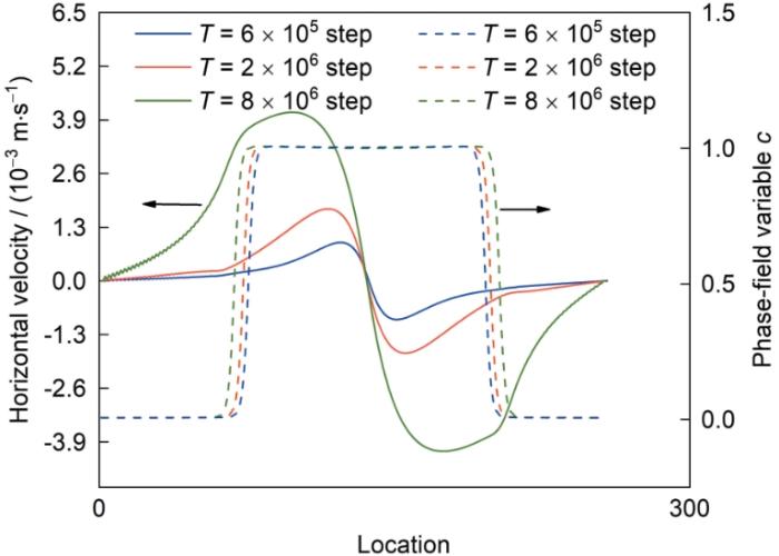
图6 为沿水平方向对称轴上的相场变量和轴向速度场的变化曲线,其中水平方向速度为正,则速度方向水平向右;反之则水平向左。可以看出,在液体颗粒接触界面上存在一个滞止点(stagnation point),该点水平方向的速率为0且在该点附近水平方向速率与距滞止点的距离成线性关系,线性变化率与轴向应变率有关且与接触面的距离成正比,该区域称为速度的接触应变区。接触应变区随着烧结颈的增大而增大。远离接触界面的区域称为刚体运动区域,距离接触面较远,因此演化过程中烧结颈变化引起的应力变化对该部分影响较小,其速度变化为单纯的黏性流体流动所引发的,速度变化较慢。沿远离对称轴的方向,液相区转变为气相区,此时轴向速度很小且迅速减为0。轴向速度模拟结果与Wakai等[27 ] 的理论分析结果一致。
图6
图6
沿水平方向对称轴上的相场变量和轴向速度场的变化曲线
Fig.6
Distributions of phase-field variable and velocity field along horizontal symmetry axis of the two circle grains
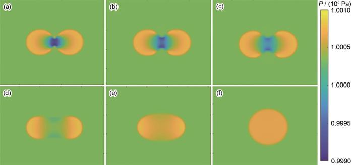
图7 为烧结过程中压强在空间的分布,可以看出由压强差造成液体颗粒的合并与演化过程。在液相颗粒的两边压强较大,中间压强较小。在液体颗粒接触面上压强分布并不均匀,而是在接触面上根据烧结颈曲率的大小进行变化。烧结颈为内凹的马鞍状,因此其曲率大于0,导致压强小于周围环境压强。伴随着时间步长的推进,烧结颈处曲率逐渐减小,烧结颈部压强与外界压差也逐渐减小,最终演化为一个液体球形颗粒时曲率变为负,此时液体颗粒内部也不存在负压强点。演化结束后,形成单个液相颗粒,内部的压强均匀分布,与文献[27 ]压强模拟结果类似。
图7
图7
等大双圆形颗粒烧结过程的压强分布
Fig.7
Pressure (P ) distributions of two equal circle grains
(a) 2 × 10⁴ step (b) 1 × 10⁵ step (c) 2 × 10⁵ step (d) 1.2 × 10⁶ step (e) 1 × 10⁷ step (f) 4 × 10⁷ step
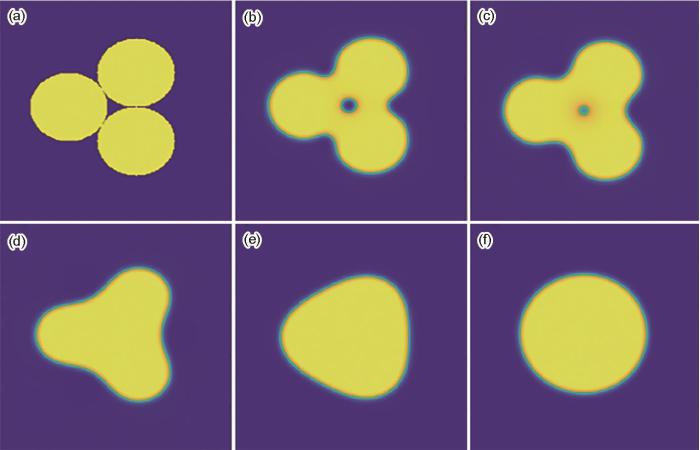
3.4 多颗粒烧结过程模拟
设定三颗粒夹角为60°,其形貌演化过程如图8 所示。由于颗粒接触的限制,三颗粒合并过程中,并没有产生过大的位移,在表面能减少驱动作用下,三颗粒最终形成单个表面能最小的圆形颗粒。可以看到,由于三颗粒之间孔隙较小,很快发生球化,液相在演化过程中填充孔隙,液相颗粒致密化。在烧结过程中,由于小孔隙的表面能较高,因此优先被填充。该处孔隙存在浮力作用,孔隙会缓慢向上迁移到达烧结顶部,导致气孔消失。模拟结果与文献[26 ]中提出颗粒黏性烧结4个阶段相同:自由流动、接触、液桥增长、气孔消失。
图8
图8
等大三颗粒烧结过程的形貌演化
Fig.8
Microstructure evolutions of three particles with the initial contact angles 60°
(a) 0 step (b) 6 × 10⁴ step (c) 2 × 10⁵ step (d) 1 × 10⁶ step (e) 6 × 10⁶ step (f) 2 × 10⁷ step
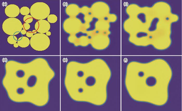
多颗粒烧结过程的形貌演变图如图9 所示。在模拟的开始阶段,选择16个尺寸和分布均随机圆形颗粒作为初始组织,颗粒之间的孔隙形状各不相同。演化过程中,在黏性烧结的初始阶段烧结颈形成,接触点扩大。中间阶段,图中蓝色圆圈中的孔隙,在该阶段先进行球化,之后被液相填充。中间阶段的颈部生长较快,通过相邻颈部的融合使得孔隙进行变化,较小孔隙迅速被液相填充,较大孔隙则发生球化现象。中间阶段结束时,孔隙闭合圆状,总孔隙率下降,此时较大孔隙并未形成完美的圆形,即红圈中的孔隙在T = 1 × 10⁵ step时,边界变得圆润但并未形成完美的圆形。最终阶段,孔隙闭合致密度增加,导致大孔隙被挤压成封闭的圆形,此时孔隙数量减少、平均尺寸增加。
图9
图9
多颗粒烧结过程的形貌演化
Fig.9
Microstructure evolutions of multi-particles (The red circle shows the region of pore spheroidization, and the blue circle shows the region of pore disappearance)
(a) 0 step (b) 2 × 10⁴ step (c) 1 × 10⁵ step (d) 2 × 10⁶ step (e) 2.4 × 10⁶ step (f) 3 × 10⁶ step
4 结论
(1) 建立了黏性烧结相场模型,通过有限差分法和投影法求解了Cahn-Hilliard方程与Navier-Stokes方程,并对等大双圆形颗粒的烧结过程进行模拟。形貌演化结果为黏弹性接触满足质量守恒;颈球比与收缩率在模拟的开始阶段变化迅速,随着演化时间的延长驱动力下降,缓慢趋近于稳定值;增大M 可以加快演化的形成,但对稳定状态的形貌影响不大。
(2) 对速度场和压强场的模拟表明,颗粒内部速度分为接触应变区和刚体运动区,接触应变区速度变化为纯应变运动,轴向速率与接触面距离成正比,刚体运动区为单纯黏性流动,速度变化较为缓慢;颗粒界面附近压强与外界压强差与该处曲率成正比,颗粒内部压强均匀分布。
(3) 多颗粒黏性烧结经历了接触点增大、烧结颈形成、相邻颈部融合等微观过程;孔隙尺寸对球化的影响很大,尺寸较小的孔隙快速发生球化并被液体填充,而尺寸较大的孔隙发生球化的速度较慢。
参考文献
View Option
[1]
German R M translated by Jia C C Chu K Liu B W et al . Sintering: From Empirical Observations to Scientific Principles [M]. Beijing : Chemical Industry Press , 2021 : 5
[本文引用: 1]
兰德尔·杰曼著 , 贾成厂 , 褚 克 , 刘博文 等 译. 烧结实践与科学原理 [M]. 北京 : 化学工业出版社 , 2021 : 5
[本文引用: 1]
[2]
German R M Suri P Park S J Review: Liquid phase sintering
[J]. J. Mater. Sci. , 2009 , 44 : 1
[本文引用: 1]
[3]
Pi H L Shi X L Xu X X Effect of SiC-ZrC coating prepared by SiZr liquid phase sintering on the oxidation resistance of C/SiC composites
[J]. Acta Metall. Sin. , 2021 , 57 : 791
DOI
[本文引用: 1]
Owing to their low density and good mechanical properties at high temperatures, C/SiC composites are increasingly used in the aerospace industry. They are also being proposed as thermal-structural materials in the hypersonic field; however, C/SiC composites are easily oxidized in high-temperature air environments. In this study, a C/SiC composite was coated with a SiC-ZrC oxidation-resistant layer by a two-step sintering method using Si-25%Zr (mass fraction) alloy, and the phase evolution of the coating was studied during the sintering. The oxidation resistance of the material was then tested at 1400oC in an air environment. The microstructural changes of the coating before and after oxidation and the effect of oxidation on the bending properties of C/SiC were analyzed. After the reaction with carbon, Si and ZrSi2 disappear in the coating, leaving only pure ZrC and SiC. The ZrC phase refined the structure of the reactive SiC layer. The grain size of the sintered SiC was 2 μm, versus 5-20 μm for SiC sintered from pure Si. The refined grains created a dense and continuous SiO2 film during the oxidation process. As the oxidation time was increased at 1400oC, the C/SiC composite with the SiC-ZrC coating began losing weight at 200 s, but began gaining weight at 500 s as a dense SiO2 film was formed. After 1000 s of oxidation, the flexural strength of the C/SiC composites was 335 MPa, only 5% lower than that of the initial C/SiC composite. According to this result, the sintered SiC-ZrC oxidation-resistant film effectively protected the mechanical properties of the C/SiC composite during the oxidation process.
皮慧龙 , 石小磊 , 徐兴祥 SiZr液相烧结法制备SiC-ZrC涂层对C/SiC复合材料抗氧化性能的影响
[J]. 金属学报 , 2021 , 57 : 791
DOI
[本文引用: 1]
使用Si-25%Zr (质量分数)合金通过液相烧结法在C/SiC复合材料表面制备了SiC-ZrC抗氧化涂层,研究了烧结过程中涂层的相结构演化,并测试了1400℃及空气气氛下材料的抗氧化性能,分析了涂层氧化前后显微结构的变化,以及氧化对C/SiC复合材料弯曲性能的影响。结果表明,Zr元素在涂层中以ZrC相的形式存在,ZrC颗粒的引入细化了反应SiC层的组织,在氧化过程中形成致密连续的SiO<sub>2</sub>薄膜,并在氧化500 s后试样出现增重,制备了SiC-ZrC抗氧化涂层的C/SiC样品在1000 s的氧化实验后弯曲强度下降低于5%。
[4]
Kraft T Riedel H Numerical simulation of solid state sintering; model and application
[J]. J. Eur. Ceram. Soc. , 2004 , 24 : 345
[本文引用: 1]
[5]
Van de Vorst G A L Mattheij R M M Numerical analysis of a 2-D viscous sintering problem with non-smooth boundaries
[J]. Computing , 1992 , 49 : 239
[本文引用: 1]
[6]
Kuiken H K Viscous sintering: The surface-tension-driven flow of a liquid form under the influence of curvature gradients at its surface
[J]. J. Fluid Mech. , 1990 , 214 : 503
[本文引用: 1]
[7]
Frenkel J J Viscous flow of crystalline bodies under the action of surface tension
[J]. J. Phys. , 1945 , 9 : 385
[本文引用: 3]
[8]
Martínez-Herrera J I Derby J J Viscous sintering of spherical particles via finite element analysis
[J]. J. Am. Ceram. Soc. , 1995 , 78 : 645
[本文引用: 1]
[9]
Hiram Y Nir A A simulation of surface tension driven coalescence
[J]. J. Colloid Interface Sci. , 1983 , 95 : 462
[本文引用: 1]
[10]
Gross M Steinbach I Raabe D et al . Viscous coalescence of droplets: A lattice Boltzmann study
[J]. Phys. Fluids , 2013 , 25 : 052101
[本文引用: 1]
[11]
Braginsky M Tikare V Olevsky E Numerical simulation of solid state sintering
[J]. Int. J. Solids Struct. , 2005 , 42 : 621
[本文引用: 1]
[12]
Yang Q C Kirshtein A Ji Y Z et al . A thermodynamically consistent phase-field model for viscous sintering
[J]. J. Am. Ceram. Soc. , 2019 , 102 : 674
DOI
[本文引用: 10]
A thermodynamically consistent phase-field model for viscous sintering is proposed. It is based on an energetic variational formulation that allows the governing equations to be analytically derived from a defined energy law. The conservation of mass is satisfied through the incompressibility assumption and the assumption that mass density is uniform initially within the particle compact while the balance of linear momentum is formulated from an energy dissipation law. The morphological changes of particles are described by the temporal and spatial evolution of a phase-field variable governed by a modified Cahn-Hilliard equation, and the motion of viscous mass flow is controlled by the Stokes equation incorporating the surface tension effect. The application of the phase-field model is illustrated by examining the effect of particle shape, initial contact angle and rearrangement effects on viscous sintering.
[13]
Landau L D Khalatikow I M The Selected Works of L.D. Landau (English Translation) [M]. Oxford : Pergamon , 1963 : 1
[本文引用: 1]
[14]
Sun Z Y Yang C Liu W B Phase field simulations of the sintering process of UO2
[J]. Acta Metall. Sin. , 2020 , 56 : 1295
[本文引用: 1]
孙正阳 , 杨 超 , 柳文波 UO2 烧结过程的相场模拟
[J]. 金属学报 , 2020 , 56 : 1295
DOI
[本文引用: 1]
利用相场模型对UO<sub>2</sub>陶瓷粉末的烧结过程进行了模拟。在修正的相场模型中,不仅考虑了表面扩散、晶界扩散和晶格扩散3种各向异性的扩散机制对烧结组织形貌和烧结动力学的影响,而且考虑了不同陶瓷颗粒之间的界面能对烧结形貌的影响。基于实验条件和热力学物性参数,对UO<sub>2</sub>陶瓷粉末在2000 K的烧结过程进行了模拟。模拟结果显示:初始形貌为圆形的陶瓷粉末有利于烧结过程的进行;烧结过程中存在大晶粒吞噬小晶粒的现象;晶界扩散机制是UO<sub>2</sub>烧结过程中的主导机制;晶界能的改变导致晶界与相界之间的平衡二面角发生改变。在此基础上,模拟了多晶UO<sub>2</sub>陶瓷粉末的烧结过程,模拟结果与实验结果吻合较好。
[15]
Wang Y U Computer modeling and simulation of solid-state sintering: A phase field approach
[J]. Acta Mater. , 2006 , 54 : 953
[本文引用: 1]
[16]
Chockalingam K Kouznetsova V G Van der Sluis O et al . 2D phase field modeling of sintering of silver nanoparticles
[J]. Comput. Meth. Appl. Mech. Eng. , 2016 , 312 : 492
[17]
Zhang X Liao Y L A phase-field model for solid-state selective laser sintering of metallic materials
[J]. Powder Technol. , 2018 , 339 : 677
[本文引用: 1]
[18]
Kumar V Fang Z Z Fife P C Phase field simulations of grain growth during sintering of two unequal-sized particles
[J]. Mater. Sci. Eng. , 2010 , A528 : 254
[本文引用: 2]
[19]
Tegze G Pusztai T Gránásy L Phase field simulation of liquid phase separation with fluid flow
[J]. Mater. Sci. Eng. , 2005 , A413 -414 : 418
[本文引用: 2]
[20]
Soligo G Roccon A Soldati A Mass-conservation-improved phase field methods for turbulent multiphase flow simulation
[J]. Acta Mech. , 2019 , 230 : 683
[本文引用: 1]
[21]
Gao Y J Lu Y J Kong L Y et al . Phase field crystal model and its application for microstructure evolution of materials
[J]. Acta Metall. Sin. , 2018 , 54 : 278
DOI
[本文引用: 2]
With the rapid development of computer technology, the roles of computer numerical simulation technology in materials are more and more prominent. Computer numerical simulation technology, real experimental observation and theoretical model analysis are the same important and are known as three great scientific research methods since the 20th century. In this paper, several important computational numerical simulation methods are briefly compared, firstly, in the spatial characteristic resolution scale and the characteristic time scale, for example, for molecular dynamics (MD), traditional phase field (TPF), and phase field crystal (PFC) method. For simulation of microstructure evolution in nano-scale, the PFC method is of the advantage on the characteristic time scale. Then, the PFC model, and its physical and mathematical basises for establishment, as well as the special feature of the method, are introduced. Next, the development of the PFC models are presented, including the PFC model of binary and multi-element alloys, of gas-liquid-solid three systems, of two-mode and multimode systems, as well as the key technology and the main procedure of the numerical calculation of the dynamic equation solution. After that, combining with the research works of the authors' group in the microstructure evolution of materials, several examples of important aspects of application of the PFC model are presented, including the nanostructure of defects of materials, dendritic growth and heterogenous epitxial growth, premelting under deformation at high temperature and dynamic recovery, extension and bifurcation of cracks on nanoscale, matalllic glass transition, defect structures of graphene, voids formation of electromigration in metal interconnects, microstructure in multiferroic composite matrials, and the formation of the structure of the metal foams. Finally, a summary is given and the development direction and future emphasis application and new fields of the PFC model are pointed out.
高英俊 , 卢昱江 , 孔令一 等 . 晶体相场模型及其在材料微结构演化中的应用
[J]. 金属学报 , 2018 , 54 : 278
DOI
[本文引用: 2]
随着计算机技术的快速发展,计算机模拟实验在材料科学中的作用越来越突出。计算机数值模拟技术已经和实验观测、理论模型分析并称为20世纪以来的三大科学研究方法。本文首先简要地从空间特征分辨尺度和时间特征尺度比较了几种重要的计算模拟方法——分子动力学(MD)、传统相场方法(TPF)和晶体相场(PFC)方法的各自适应的特征尺度范围和特点。在模拟纳观尺度的材料微结构演化,PFC在特征时间尺度上更具优势。其次,介绍了PFC模型,及其建立的物理基础和数学基础,以及该方法的特色优势。同时,介绍该PFC模型的拓展与推广,包括二元和多元体系、气-液-固三相体系、双模和多模体系的PFC模型,以及求解PFC模型的动力学方程数值计算的关键技术与主要步骤。再次,结合作者在材料微结构演化方面的研究,着重介绍PFC模型的几个重要方面的应用例子,包括材料纳观缺陷结构演化、凝固的枝晶生长和晶体外延生长、高温预熔化变形和动态回复、纳观尺度的裂纹扩展与分叉、无序-有序金属玻璃转变、石墨烯的缺陷结构、金属互联线电迁移空洞、多铁复合材料的畴结构、金属泡沫结构的生成等。最后,总结并指出PFC模型的拓展方向与今后应用的重点方面和新领域。
[22]
Zografos K Afonso A M Poole R J et al . A viscoelastic two-phase solver using a phase-field approach
[J]. J. Non-Newton. Fluid Mech. , 2020 , 284 : 104364
[23]
Balemans C Hulsen M A Anderson P D Sintering of two viscoelastic particles: A computational approach
[J]. Appl. Sci. , 2017 , 7 : 516
[本文引用: 9]
[24]
Kim J Phase-field models for multi-component fluid flows
[J]. Commun. Comput. Phys. , 2012 , 12 : 613
[本文引用: 2]
[25]
Lin Y Y Hui C Y Jagota A The role of viscoelastic adhesive contact in the sintering of polymeric particles
[J]. J. Colloid Interface Sci. , 2001 , 237 : 267
[本文引用: 1]
[26]
Kamyabi M Sotudeh-Gharebagh R Zarghami R et al . Principles of viscous sintering in amorphous powders: A critical review
[J]. Chem. Eng. Res. Des. , 2017 , 125 : 328
[本文引用: 2]
[27]
Wakai F Katsura K Kanchika S et al . Sintering force behind the viscous sintering of two particles
[J]. Acta Mater. , 2016 , 109 : 292
[本文引用: 2]
1
2021
... 烧结是通过加热使粉末颗粒结合成块状材料的过程.烧结过程可以分为3类:晶体材料烧结、非晶材料烧结(即黏性烧结)以及液相烧结[1 ] ,其中黏性烧结和液相烧结均涉及液相.烧结过程中液相能够润湿固体颗粒并提供毛细力,从而加快烧结颗粒的演化,改善烧结组织和物理性能[2 ,3 ] .表面张力作用下引起的颗粒变形和凝聚是晶体材料固相烧结的主要驱动力[4 ] ,经过多年的发展,该理论已经比较成熟.当烧结温度高于晶体熔点时,材料可被当作黏性不可压缩Newton流体,表面张力与材料黏性引起颗粒变形和凝聚,该过程称为黏性烧结过程[5 ,6 ] .黏性烧结过程的数值模拟涉及烧结扩散理论与Navier-Stokes流体方程的耦合问题,相关模型的建立仍然具有很大的挑战. ...
Review: Liquid phase sintering
1
2009
... 烧结是通过加热使粉末颗粒结合成块状材料的过程.烧结过程可以分为3类:晶体材料烧结、非晶材料烧结(即黏性烧结)以及液相烧结[1 ] ,其中黏性烧结和液相烧结均涉及液相.烧结过程中液相能够润湿固体颗粒并提供毛细力,从而加快烧结颗粒的演化,改善烧结组织和物理性能[2 ,3 ] .表面张力作用下引起的颗粒变形和凝聚是晶体材料固相烧结的主要驱动力[4 ] ,经过多年的发展,该理论已经比较成熟.当烧结温度高于晶体熔点时,材料可被当作黏性不可压缩Newton流体,表面张力与材料黏性引起颗粒变形和凝聚,该过程称为黏性烧结过程[5 ,6 ] .黏性烧结过程的数值模拟涉及烧结扩散理论与Navier-Stokes流体方程的耦合问题,相关模型的建立仍然具有很大的挑战. ...
Effect of SiC-ZrC coating prepared by SiZr liquid phase sintering on the oxidation resistance of C/SiC composites
1
2021
... 烧结是通过加热使粉末颗粒结合成块状材料的过程.烧结过程可以分为3类:晶体材料烧结、非晶材料烧结(即黏性烧结)以及液相烧结[1 ] ,其中黏性烧结和液相烧结均涉及液相.烧结过程中液相能够润湿固体颗粒并提供毛细力,从而加快烧结颗粒的演化,改善烧结组织和物理性能[2 ,3 ] .表面张力作用下引起的颗粒变形和凝聚是晶体材料固相烧结的主要驱动力[4 ] ,经过多年的发展,该理论已经比较成熟.当烧结温度高于晶体熔点时,材料可被当作黏性不可压缩Newton流体,表面张力与材料黏性引起颗粒变形和凝聚,该过程称为黏性烧结过程[5 ,6 ] .黏性烧结过程的数值模拟涉及烧结扩散理论与Navier-Stokes流体方程的耦合问题,相关模型的建立仍然具有很大的挑战. ...
SiZr液相烧结法制备SiC-ZrC涂层对C/SiC复合材料抗氧化性能的影响
1
2021
... 烧结是通过加热使粉末颗粒结合成块状材料的过程.烧结过程可以分为3类:晶体材料烧结、非晶材料烧结(即黏性烧结)以及液相烧结[1 ] ,其中黏性烧结和液相烧结均涉及液相.烧结过程中液相能够润湿固体颗粒并提供毛细力,从而加快烧结颗粒的演化,改善烧结组织和物理性能[2 ,3 ] .表面张力作用下引起的颗粒变形和凝聚是晶体材料固相烧结的主要驱动力[4 ] ,经过多年的发展,该理论已经比较成熟.当烧结温度高于晶体熔点时,材料可被当作黏性不可压缩Newton流体,表面张力与材料黏性引起颗粒变形和凝聚,该过程称为黏性烧结过程[5 ,6 ] .黏性烧结过程的数值模拟涉及烧结扩散理论与Navier-Stokes流体方程的耦合问题,相关模型的建立仍然具有很大的挑战. ...
Numerical simulation of solid state sintering; model and application
1
2004
... 烧结是通过加热使粉末颗粒结合成块状材料的过程.烧结过程可以分为3类:晶体材料烧结、非晶材料烧结(即黏性烧结)以及液相烧结[1 ] ,其中黏性烧结和液相烧结均涉及液相.烧结过程中液相能够润湿固体颗粒并提供毛细力,从而加快烧结颗粒的演化,改善烧结组织和物理性能[2 ,3 ] .表面张力作用下引起的颗粒变形和凝聚是晶体材料固相烧结的主要驱动力[4 ] ,经过多年的发展,该理论已经比较成熟.当烧结温度高于晶体熔点时,材料可被当作黏性不可压缩Newton流体,表面张力与材料黏性引起颗粒变形和凝聚,该过程称为黏性烧结过程[5 ,6 ] .黏性烧结过程的数值模拟涉及烧结扩散理论与Navier-Stokes流体方程的耦合问题,相关模型的建立仍然具有很大的挑战. ...
Numerical analysis of a 2-D viscous sintering problem with non-smooth boundaries
1
1992
... 烧结是通过加热使粉末颗粒结合成块状材料的过程.烧结过程可以分为3类:晶体材料烧结、非晶材料烧结(即黏性烧结)以及液相烧结[1 ] ,其中黏性烧结和液相烧结均涉及液相.烧结过程中液相能够润湿固体颗粒并提供毛细力,从而加快烧结颗粒的演化,改善烧结组织和物理性能[2 ,3 ] .表面张力作用下引起的颗粒变形和凝聚是晶体材料固相烧结的主要驱动力[4 ] ,经过多年的发展,该理论已经比较成熟.当烧结温度高于晶体熔点时,材料可被当作黏性不可压缩Newton流体,表面张力与材料黏性引起颗粒变形和凝聚,该过程称为黏性烧结过程[5 ,6 ] .黏性烧结过程的数值模拟涉及烧结扩散理论与Navier-Stokes流体方程的耦合问题,相关模型的建立仍然具有很大的挑战. ...
Viscous sintering: The surface-tension-driven flow of a liquid form under the influence of curvature gradients at its surface
1
1990
... 烧结是通过加热使粉末颗粒结合成块状材料的过程.烧结过程可以分为3类:晶体材料烧结、非晶材料烧结(即黏性烧结)以及液相烧结[1 ] ,其中黏性烧结和液相烧结均涉及液相.烧结过程中液相能够润湿固体颗粒并提供毛细力,从而加快烧结颗粒的演化,改善烧结组织和物理性能[2 ,3 ] .表面张力作用下引起的颗粒变形和凝聚是晶体材料固相烧结的主要驱动力[4 ] ,经过多年的发展,该理论已经比较成熟.当烧结温度高于晶体熔点时,材料可被当作黏性不可压缩Newton流体,表面张力与材料黏性引起颗粒变形和凝聚,该过程称为黏性烧结过程[5 ,6 ] .黏性烧结过程的数值模拟涉及烧结扩散理论与Navier-Stokes流体方程的耦合问题,相关模型的建立仍然具有很大的挑战. ...
Viscous flow of crystalline bodies under the action of surface tension
3
1945
... 长期以来,国内外学者对黏性烧结的数值模拟开展了一些研究[7 ~12 ] .黏性烧结模拟最早由Frenkel[7 ] 提出,该模型认为:在表面能作用下,2个点接触的黏性球体颗粒合并过程中半径不变,最终合并为一个大的球体颗粒.目前描述黏性烧结的主要方法有:有限元法[8 ] 、边界积分法[9 ] 、格子Boltzmann法(lattice Boltzmann method,LBM)[10 ] 、Monte Carlo方法[11 ] 、相场方法[12 ] 等.其中,基于Ginzburg-Landau[13 ] 理论的相场方法对界面做了弥散化处理,可以有效追踪界面的动态演变过程;而且相场方法同时考虑了烧结的热力学因素和动力学过程.因此,相场方法可以更好地模拟和再现黏性烧结过程中颗粒内部的演化过程. ...
... [7 ]提出,该模型认为:在表面能作用下,2个点接触的黏性球体颗粒合并过程中半径不变,最终合并为一个大的球体颗粒.目前描述黏性烧结的主要方法有:有限元法[8 ] 、边界积分法[9 ] 、格子Boltzmann法(lattice Boltzmann method,LBM)[10 ] 、Monte Carlo方法[11 ] 、相场方法[12 ] 等.其中,基于Ginzburg-Landau[13 ] 理论的相场方法对界面做了弥散化处理,可以有效追踪界面的动态演变过程;而且相场方法同时考虑了烧结的热力学因素和动力学过程.因此,相场方法可以更好地模拟和再现黏性烧结过程中颗粒内部的演化过程. ...
... 图3 和4 分别为不同迁移率下的颈球比和收缩率随演化时间步的变化关系.其中,T 表示时间步;颈球比为X / D (其中,X 为t 时刻烧结颈的长度,D 为t 时刻的粒径);收缩率为(2D - L ) / D (其中,L 为双颗粒演化过程中的长度).可以看出,颈球比和收缩率变化趋势一致,烧结开始阶段变化较快,随着时间的延长变得缓慢.由于开始时不平衡,驱动力较大,在2 × 10⁷ 时间步后,变化速度明显变慢.随着迁移率的增大,整体演化速率加快,整体演化趋势不变,且最终稳定的值并不发生改变.进一步分析发现,模拟后期的颈球比为1.411 (接近2 ) ,而收缩率为0.588 (接近2 - 2 d d t ∫ c d Ω = 0 . Frenkel基于原子扩散和黏性流动的类比,提出的烧结模型的模拟结果颗粒半径不发生变化[7 ] ;且颈球比随时间的变化为( X D ) 2 ∝ t . 本工作中,颗粒演化过程的模拟结果,接近黏弹性接触(viscoelastic contact),与文献[26 ]中颈球比随时间变化函数相似. ...
Viscous sintering of spherical particles via finite element analysis
1
1995
... 长期以来,国内外学者对黏性烧结的数值模拟开展了一些研究[7 ~12 ] .黏性烧结模拟最早由Frenkel[7 ] 提出,该模型认为:在表面能作用下,2个点接触的黏性球体颗粒合并过程中半径不变,最终合并为一个大的球体颗粒.目前描述黏性烧结的主要方法有:有限元法[8 ] 、边界积分法[9 ] 、格子Boltzmann法(lattice Boltzmann method,LBM)[10 ] 、Monte Carlo方法[11 ] 、相场方法[12 ] 等.其中,基于Ginzburg-Landau[13 ] 理论的相场方法对界面做了弥散化处理,可以有效追踪界面的动态演变过程;而且相场方法同时考虑了烧结的热力学因素和动力学过程.因此,相场方法可以更好地模拟和再现黏性烧结过程中颗粒内部的演化过程. ...
A simulation of surface tension driven coalescence
1
1983
... 长期以来,国内外学者对黏性烧结的数值模拟开展了一些研究[7 ~12 ] .黏性烧结模拟最早由Frenkel[7 ] 提出,该模型认为:在表面能作用下,2个点接触的黏性球体颗粒合并过程中半径不变,最终合并为一个大的球体颗粒.目前描述黏性烧结的主要方法有:有限元法[8 ] 、边界积分法[9 ] 、格子Boltzmann法(lattice Boltzmann method,LBM)[10 ] 、Monte Carlo方法[11 ] 、相场方法[12 ] 等.其中,基于Ginzburg-Landau[13 ] 理论的相场方法对界面做了弥散化处理,可以有效追踪界面的动态演变过程;而且相场方法同时考虑了烧结的热力学因素和动力学过程.因此,相场方法可以更好地模拟和再现黏性烧结过程中颗粒内部的演化过程. ...
Viscous coalescence of droplets: A lattice Boltzmann study
1
2013
... 长期以来,国内外学者对黏性烧结的数值模拟开展了一些研究[7 ~12 ] .黏性烧结模拟最早由Frenkel[7 ] 提出,该模型认为:在表面能作用下,2个点接触的黏性球体颗粒合并过程中半径不变,最终合并为一个大的球体颗粒.目前描述黏性烧结的主要方法有:有限元法[8 ] 、边界积分法[9 ] 、格子Boltzmann法(lattice Boltzmann method,LBM)[10 ] 、Monte Carlo方法[11 ] 、相场方法[12 ] 等.其中,基于Ginzburg-Landau[13 ] 理论的相场方法对界面做了弥散化处理,可以有效追踪界面的动态演变过程;而且相场方法同时考虑了烧结的热力学因素和动力学过程.因此,相场方法可以更好地模拟和再现黏性烧结过程中颗粒内部的演化过程. ...
Numerical simulation of solid state sintering
1
2005
... 长期以来,国内外学者对黏性烧结的数值模拟开展了一些研究[7 ~12 ] .黏性烧结模拟最早由Frenkel[7 ] 提出,该模型认为:在表面能作用下,2个点接触的黏性球体颗粒合并过程中半径不变,最终合并为一个大的球体颗粒.目前描述黏性烧结的主要方法有:有限元法[8 ] 、边界积分法[9 ] 、格子Boltzmann法(lattice Boltzmann method,LBM)[10 ] 、Monte Carlo方法[11 ] 、相场方法[12 ] 等.其中,基于Ginzburg-Landau[13 ] 理论的相场方法对界面做了弥散化处理,可以有效追踪界面的动态演变过程;而且相场方法同时考虑了烧结的热力学因素和动力学过程.因此,相场方法可以更好地模拟和再现黏性烧结过程中颗粒内部的演化过程. ...
A thermodynamically consistent phase-field model for viscous sintering
10
2019
... 长期以来,国内外学者对黏性烧结的数值模拟开展了一些研究[7 ~12 ] .黏性烧结模拟最早由Frenkel[7 ] 提出,该模型认为:在表面能作用下,2个点接触的黏性球体颗粒合并过程中半径不变,最终合并为一个大的球体颗粒.目前描述黏性烧结的主要方法有:有限元法[8 ] 、边界积分法[9 ] 、格子Boltzmann法(lattice Boltzmann method,LBM)[10 ] 、Monte Carlo方法[11 ] 、相场方法[12 ] 等.其中,基于Ginzburg-Landau[13 ] 理论的相场方法对界面做了弥散化处理,可以有效追踪界面的动态演变过程;而且相场方法同时考虑了烧结的热力学因素和动力学过程.因此,相场方法可以更好地模拟和再现黏性烧结过程中颗粒内部的演化过程. ...
... [12 ]等.其中,基于Ginzburg-Landau[13 ] 理论的相场方法对界面做了弥散化处理,可以有效追踪界面的动态演变过程;而且相场方法同时考虑了烧结的热力学因素和动力学过程.因此,相场方法可以更好地模拟和再现黏性烧结过程中颗粒内部的演化过程. ...
... 本工作烧结相场模型的总自由能泛函数(F )采用以下形式[12 ] : ...
... 本工作中体自由能密度f (c ) = 0.25Ac 2 (1-c )2 [12 ] ,其中A 为局部自由能参数.参数A 和κc 的表达式分别为[12 ] : ...
... [12 ]: ...
... 式中,M 为迁移率,本工作采用常量形式[12 ] ; V δ F δ c
... 在多颗粒黏性烧结模拟过程中,为了便于数值求解,需对方程中的变量和常量进行无量纲化处理:先选取一组参考物理量,然后用模型中变量除以参考量得到无量纲量.其中基本物理参数如表1 [12 ,23 ] 所示,本工作选取的参考量为参考能量密度ε * 、参考时间t * 、参考长度l * .将各参量代入演化方程,进行无量纲化后各参数可表示为:M ˜ = t * ε * ( l * ) 2 M A ˜ = A ε * κ ˜ c = κ c ε * ( l * ) 2 ρ ˜ = ( l * ) 2 ε * ( t * ) 2 ρ V ˜ = t * l * V μ ˜ = t * ε * μ ∇ ˜ = l * ∇ p ˜ = p ε * t ˜ = t t * . 式中,M ˜ A ˜ κ ˜ c ρ ˜ V ˜ μ ˜ ∇ ˜ p ˜ t ˜
... 175℃下尼龙12的物理参数[12 ,23 ] ...
... Physical parameters of nylon 12 (PA12) at 175o C[12 ,23 ] ...
... [
12 ]
Δx 0.825 nm σ 0.03 N·m-1 [23 ] Note: ρ liquid —sintered material's density, ρ gas —gas density, μ liquid —sintered material's viscosity, μ gas —gas viscosity, M —surface mobility, Δx— space scale, σ —surface tension coefficient ...
1
1963
... 长期以来,国内外学者对黏性烧结的数值模拟开展了一些研究[7 ~12 ] .黏性烧结模拟最早由Frenkel[7 ] 提出,该模型认为:在表面能作用下,2个点接触的黏性球体颗粒合并过程中半径不变,最终合并为一个大的球体颗粒.目前描述黏性烧结的主要方法有:有限元法[8 ] 、边界积分法[9 ] 、格子Boltzmann法(lattice Boltzmann method,LBM)[10 ] 、Monte Carlo方法[11 ] 、相场方法[12 ] 等.其中,基于Ginzburg-Landau[13 ] 理论的相场方法对界面做了弥散化处理,可以有效追踪界面的动态演变过程;而且相场方法同时考虑了烧结的热力学因素和动力学过程.因此,相场方法可以更好地模拟和再现黏性烧结过程中颗粒内部的演化过程. ...
Phase field simulations of the sintering process of UO2
1
2020
... 近年来,相场方法已被成功利用于模拟固相烧结过程中界面和气孔形貌演化的研究中[14 ~18 ] .Wang[15 ] 考虑了刚体平移和旋转、边界迁移的颗粒长大以及各种扩散机制,对相场方程的对流项进行了修正.Zhang和Liao[17 ] 构造激光烧结的相场模型,模拟了金属材料的固态激光烧结过程,与扫描电镜实验结果吻合较好.Kumar等[18 ] 研究了固体非等大颗粒的烧结演化,将烧结过程总结为烧结颈形成、颗粒边界缓慢合并迁移、颗粒边界快速迁移3个子过程.然而,上述相场模型均集中在晶体材料的固相烧结领域,因此开发能准确描述液相烧结过程的相场模型非常重要.液相烧结过程涉及流场,因此液相烧结模型需要考虑更复杂的物理过程[19 ~21 ] .Tegze等[19 ] 利用相场方法模拟了亚稳态液体和玻璃相的分离过程,讨论了由液滴Brown运动引起的凝固过程、蒸发冷凝过程、扩散耦合过程中液滴尺寸分布情况.Soligo等[20 ] 考虑了气泡在静止流体中上升和层流剪切流的相互作用,修正了相场公式求解湍流的多相流问题.高英俊等[21 ] 利用晶体相场模型研究了环境温度达到固-液共存温度时,在外加应变作用下的小角度晶界、位错的湮灭过程以及外加应力与预熔化区域之间的关系.上述模型为黏性烧结相场模型的开发提供了一些思路,但完整准确地描述黏性烧结的形貌演变和流场等工作需要耦合Cahn-Hilliard方程与Navier-Stokes方程并进行准确求解. ...
UO2 烧结过程的相场模拟
1
2020
... 近年来,相场方法已被成功利用于模拟固相烧结过程中界面和气孔形貌演化的研究中[14 ~18 ] .Wang[15 ] 考虑了刚体平移和旋转、边界迁移的颗粒长大以及各种扩散机制,对相场方程的对流项进行了修正.Zhang和Liao[17 ] 构造激光烧结的相场模型,模拟了金属材料的固态激光烧结过程,与扫描电镜实验结果吻合较好.Kumar等[18 ] 研究了固体非等大颗粒的烧结演化,将烧结过程总结为烧结颈形成、颗粒边界缓慢合并迁移、颗粒边界快速迁移3个子过程.然而,上述相场模型均集中在晶体材料的固相烧结领域,因此开发能准确描述液相烧结过程的相场模型非常重要.液相烧结过程涉及流场,因此液相烧结模型需要考虑更复杂的物理过程[19 ~21 ] .Tegze等[19 ] 利用相场方法模拟了亚稳态液体和玻璃相的分离过程,讨论了由液滴Brown运动引起的凝固过程、蒸发冷凝过程、扩散耦合过程中液滴尺寸分布情况.Soligo等[20 ] 考虑了气泡在静止流体中上升和层流剪切流的相互作用,修正了相场公式求解湍流的多相流问题.高英俊等[21 ] 利用晶体相场模型研究了环境温度达到固-液共存温度时,在外加应变作用下的小角度晶界、位错的湮灭过程以及外加应力与预熔化区域之间的关系.上述模型为黏性烧结相场模型的开发提供了一些思路,但完整准确地描述黏性烧结的形貌演变和流场等工作需要耦合Cahn-Hilliard方程与Navier-Stokes方程并进行准确求解. ...
Computer modeling and simulation of solid-state sintering: A phase field approach
1
2006
... 近年来,相场方法已被成功利用于模拟固相烧结过程中界面和气孔形貌演化的研究中[14 ~18 ] .Wang[15 ] 考虑了刚体平移和旋转、边界迁移的颗粒长大以及各种扩散机制,对相场方程的对流项进行了修正.Zhang和Liao[17 ] 构造激光烧结的相场模型,模拟了金属材料的固态激光烧结过程,与扫描电镜实验结果吻合较好.Kumar等[18 ] 研究了固体非等大颗粒的烧结演化,将烧结过程总结为烧结颈形成、颗粒边界缓慢合并迁移、颗粒边界快速迁移3个子过程.然而,上述相场模型均集中在晶体材料的固相烧结领域,因此开发能准确描述液相烧结过程的相场模型非常重要.液相烧结过程涉及流场,因此液相烧结模型需要考虑更复杂的物理过程[19 ~21 ] .Tegze等[19 ] 利用相场方法模拟了亚稳态液体和玻璃相的分离过程,讨论了由液滴Brown运动引起的凝固过程、蒸发冷凝过程、扩散耦合过程中液滴尺寸分布情况.Soligo等[20 ] 考虑了气泡在静止流体中上升和层流剪切流的相互作用,修正了相场公式求解湍流的多相流问题.高英俊等[21 ] 利用晶体相场模型研究了环境温度达到固-液共存温度时,在外加应变作用下的小角度晶界、位错的湮灭过程以及外加应力与预熔化区域之间的关系.上述模型为黏性烧结相场模型的开发提供了一些思路,但完整准确地描述黏性烧结的形貌演变和流场等工作需要耦合Cahn-Hilliard方程与Navier-Stokes方程并进行准确求解. ...
2D phase field modeling of sintering of silver nanoparticles
0
2016
A phase-field model for solid-state selective laser sintering of metallic materials
1
2018
... 近年来,相场方法已被成功利用于模拟固相烧结过程中界面和气孔形貌演化的研究中[14 ~18 ] .Wang[15 ] 考虑了刚体平移和旋转、边界迁移的颗粒长大以及各种扩散机制,对相场方程的对流项进行了修正.Zhang和Liao[17 ] 构造激光烧结的相场模型,模拟了金属材料的固态激光烧结过程,与扫描电镜实验结果吻合较好.Kumar等[18 ] 研究了固体非等大颗粒的烧结演化,将烧结过程总结为烧结颈形成、颗粒边界缓慢合并迁移、颗粒边界快速迁移3个子过程.然而,上述相场模型均集中在晶体材料的固相烧结领域,因此开发能准确描述液相烧结过程的相场模型非常重要.液相烧结过程涉及流场,因此液相烧结模型需要考虑更复杂的物理过程[19 ~21 ] .Tegze等[19 ] 利用相场方法模拟了亚稳态液体和玻璃相的分离过程,讨论了由液滴Brown运动引起的凝固过程、蒸发冷凝过程、扩散耦合过程中液滴尺寸分布情况.Soligo等[20 ] 考虑了气泡在静止流体中上升和层流剪切流的相互作用,修正了相场公式求解湍流的多相流问题.高英俊等[21 ] 利用晶体相场模型研究了环境温度达到固-液共存温度时,在外加应变作用下的小角度晶界、位错的湮灭过程以及外加应力与预熔化区域之间的关系.上述模型为黏性烧结相场模型的开发提供了一些思路,但完整准确地描述黏性烧结的形貌演变和流场等工作需要耦合Cahn-Hilliard方程与Navier-Stokes方程并进行准确求解. ...
Phase field simulations of grain growth during sintering of two unequal-sized particles
2
2010
... 近年来,相场方法已被成功利用于模拟固相烧结过程中界面和气孔形貌演化的研究中[14 ~18 ] .Wang[15 ] 考虑了刚体平移和旋转、边界迁移的颗粒长大以及各种扩散机制,对相场方程的对流项进行了修正.Zhang和Liao[17 ] 构造激光烧结的相场模型,模拟了金属材料的固态激光烧结过程,与扫描电镜实验结果吻合较好.Kumar等[18 ] 研究了固体非等大颗粒的烧结演化,将烧结过程总结为烧结颈形成、颗粒边界缓慢合并迁移、颗粒边界快速迁移3个子过程.然而,上述相场模型均集中在晶体材料的固相烧结领域,因此开发能准确描述液相烧结过程的相场模型非常重要.液相烧结过程涉及流场,因此液相烧结模型需要考虑更复杂的物理过程[19 ~21 ] .Tegze等[19 ] 利用相场方法模拟了亚稳态液体和玻璃相的分离过程,讨论了由液滴Brown运动引起的凝固过程、蒸发冷凝过程、扩散耦合过程中液滴尺寸分布情况.Soligo等[20 ] 考虑了气泡在静止流体中上升和层流剪切流的相互作用,修正了相场公式求解湍流的多相流问题.高英俊等[21 ] 利用晶体相场模型研究了环境温度达到固-液共存温度时,在外加应变作用下的小角度晶界、位错的湮灭过程以及外加应力与预熔化区域之间的关系.上述模型为黏性烧结相场模型的开发提供了一些思路,但完整准确地描述黏性烧结的形貌演变和流场等工作需要耦合Cahn-Hilliard方程与Navier-Stokes方程并进行准确求解. ...
... [18 ]研究了固体非等大颗粒的烧结演化,将烧结过程总结为烧结颈形成、颗粒边界缓慢合并迁移、颗粒边界快速迁移3个子过程.然而,上述相场模型均集中在晶体材料的固相烧结领域,因此开发能准确描述液相烧结过程的相场模型非常重要.液相烧结过程涉及流场,因此液相烧结模型需要考虑更复杂的物理过程[19 ~21 ] .Tegze等[19 ] 利用相场方法模拟了亚稳态液体和玻璃相的分离过程,讨论了由液滴Brown运动引起的凝固过程、蒸发冷凝过程、扩散耦合过程中液滴尺寸分布情况.Soligo等[20 ] 考虑了气泡在静止流体中上升和层流剪切流的相互作用,修正了相场公式求解湍流的多相流问题.高英俊等[21 ] 利用晶体相场模型研究了环境温度达到固-液共存温度时,在外加应变作用下的小角度晶界、位错的湮灭过程以及外加应力与预熔化区域之间的关系.上述模型为黏性烧结相场模型的开发提供了一些思路,但完整准确地描述黏性烧结的形貌演变和流场等工作需要耦合Cahn-Hilliard方程与Navier-Stokes方程并进行准确求解. ...
Phase field simulation of liquid phase separation with fluid flow
2
2005
... 近年来,相场方法已被成功利用于模拟固相烧结过程中界面和气孔形貌演化的研究中[14 ~18 ] .Wang[15 ] 考虑了刚体平移和旋转、边界迁移的颗粒长大以及各种扩散机制,对相场方程的对流项进行了修正.Zhang和Liao[17 ] 构造激光烧结的相场模型,模拟了金属材料的固态激光烧结过程,与扫描电镜实验结果吻合较好.Kumar等[18 ] 研究了固体非等大颗粒的烧结演化,将烧结过程总结为烧结颈形成、颗粒边界缓慢合并迁移、颗粒边界快速迁移3个子过程.然而,上述相场模型均集中在晶体材料的固相烧结领域,因此开发能准确描述液相烧结过程的相场模型非常重要.液相烧结过程涉及流场,因此液相烧结模型需要考虑更复杂的物理过程[19 ~21 ] .Tegze等[19 ] 利用相场方法模拟了亚稳态液体和玻璃相的分离过程,讨论了由液滴Brown运动引起的凝固过程、蒸发冷凝过程、扩散耦合过程中液滴尺寸分布情况.Soligo等[20 ] 考虑了气泡在静止流体中上升和层流剪切流的相互作用,修正了相场公式求解湍流的多相流问题.高英俊等[21 ] 利用晶体相场模型研究了环境温度达到固-液共存温度时,在外加应变作用下的小角度晶界、位错的湮灭过程以及外加应力与预熔化区域之间的关系.上述模型为黏性烧结相场模型的开发提供了一些思路,但完整准确地描述黏性烧结的形貌演变和流场等工作需要耦合Cahn-Hilliard方程与Navier-Stokes方程并进行准确求解. ...
... [19 ]利用相场方法模拟了亚稳态液体和玻璃相的分离过程,讨论了由液滴Brown运动引起的凝固过程、蒸发冷凝过程、扩散耦合过程中液滴尺寸分布情况.Soligo等[20 ] 考虑了气泡在静止流体中上升和层流剪切流的相互作用,修正了相场公式求解湍流的多相流问题.高英俊等[21 ] 利用晶体相场模型研究了环境温度达到固-液共存温度时,在外加应变作用下的小角度晶界、位错的湮灭过程以及外加应力与预熔化区域之间的关系.上述模型为黏性烧结相场模型的开发提供了一些思路,但完整准确地描述黏性烧结的形貌演变和流场等工作需要耦合Cahn-Hilliard方程与Navier-Stokes方程并进行准确求解. ...
Mass-conservation-improved phase field methods for turbulent multiphase flow simulation
1
2019
... 近年来,相场方法已被成功利用于模拟固相烧结过程中界面和气孔形貌演化的研究中[14 ~18 ] .Wang[15 ] 考虑了刚体平移和旋转、边界迁移的颗粒长大以及各种扩散机制,对相场方程的对流项进行了修正.Zhang和Liao[17 ] 构造激光烧结的相场模型,模拟了金属材料的固态激光烧结过程,与扫描电镜实验结果吻合较好.Kumar等[18 ] 研究了固体非等大颗粒的烧结演化,将烧结过程总结为烧结颈形成、颗粒边界缓慢合并迁移、颗粒边界快速迁移3个子过程.然而,上述相场模型均集中在晶体材料的固相烧结领域,因此开发能准确描述液相烧结过程的相场模型非常重要.液相烧结过程涉及流场,因此液相烧结模型需要考虑更复杂的物理过程[19 ~21 ] .Tegze等[19 ] 利用相场方法模拟了亚稳态液体和玻璃相的分离过程,讨论了由液滴Brown运动引起的凝固过程、蒸发冷凝过程、扩散耦合过程中液滴尺寸分布情况.Soligo等[20 ] 考虑了气泡在静止流体中上升和层流剪切流的相互作用,修正了相场公式求解湍流的多相流问题.高英俊等[21 ] 利用晶体相场模型研究了环境温度达到固-液共存温度时,在外加应变作用下的小角度晶界、位错的湮灭过程以及外加应力与预熔化区域之间的关系.上述模型为黏性烧结相场模型的开发提供了一些思路,但完整准确地描述黏性烧结的形貌演变和流场等工作需要耦合Cahn-Hilliard方程与Navier-Stokes方程并进行准确求解. ...
Phase field crystal model and its application for microstructure evolution of materials
2
2018
... 近年来,相场方法已被成功利用于模拟固相烧结过程中界面和气孔形貌演化的研究中[14 ~18 ] .Wang[15 ] 考虑了刚体平移和旋转、边界迁移的颗粒长大以及各种扩散机制,对相场方程的对流项进行了修正.Zhang和Liao[17 ] 构造激光烧结的相场模型,模拟了金属材料的固态激光烧结过程,与扫描电镜实验结果吻合较好.Kumar等[18 ] 研究了固体非等大颗粒的烧结演化,将烧结过程总结为烧结颈形成、颗粒边界缓慢合并迁移、颗粒边界快速迁移3个子过程.然而,上述相场模型均集中在晶体材料的固相烧结领域,因此开发能准确描述液相烧结过程的相场模型非常重要.液相烧结过程涉及流场,因此液相烧结模型需要考虑更复杂的物理过程[19 ~21 ] .Tegze等[19 ] 利用相场方法模拟了亚稳态液体和玻璃相的分离过程,讨论了由液滴Brown运动引起的凝固过程、蒸发冷凝过程、扩散耦合过程中液滴尺寸分布情况.Soligo等[20 ] 考虑了气泡在静止流体中上升和层流剪切流的相互作用,修正了相场公式求解湍流的多相流问题.高英俊等[21 ] 利用晶体相场模型研究了环境温度达到固-液共存温度时,在外加应变作用下的小角度晶界、位错的湮灭过程以及外加应力与预熔化区域之间的关系.上述模型为黏性烧结相场模型的开发提供了一些思路,但完整准确地描述黏性烧结的形貌演变和流场等工作需要耦合Cahn-Hilliard方程与Navier-Stokes方程并进行准确求解. ...
... [21 ]利用晶体相场模型研究了环境温度达到固-液共存温度时,在外加应变作用下的小角度晶界、位错的湮灭过程以及外加应力与预熔化区域之间的关系.上述模型为黏性烧结相场模型的开发提供了一些思路,但完整准确地描述黏性烧结的形貌演变和流场等工作需要耦合Cahn-Hilliard方程与Navier-Stokes方程并进行准确求解. ...
晶体相场模型及其在材料微结构演化中的应用
2
2018
... 近年来,相场方法已被成功利用于模拟固相烧结过程中界面和气孔形貌演化的研究中[14 ~18 ] .Wang[15 ] 考虑了刚体平移和旋转、边界迁移的颗粒长大以及各种扩散机制,对相场方程的对流项进行了修正.Zhang和Liao[17 ] 构造激光烧结的相场模型,模拟了金属材料的固态激光烧结过程,与扫描电镜实验结果吻合较好.Kumar等[18 ] 研究了固体非等大颗粒的烧结演化,将烧结过程总结为烧结颈形成、颗粒边界缓慢合并迁移、颗粒边界快速迁移3个子过程.然而,上述相场模型均集中在晶体材料的固相烧结领域,因此开发能准确描述液相烧结过程的相场模型非常重要.液相烧结过程涉及流场,因此液相烧结模型需要考虑更复杂的物理过程[19 ~21 ] .Tegze等[19 ] 利用相场方法模拟了亚稳态液体和玻璃相的分离过程,讨论了由液滴Brown运动引起的凝固过程、蒸发冷凝过程、扩散耦合过程中液滴尺寸分布情况.Soligo等[20 ] 考虑了气泡在静止流体中上升和层流剪切流的相互作用,修正了相场公式求解湍流的多相流问题.高英俊等[21 ] 利用晶体相场模型研究了环境温度达到固-液共存温度时,在外加应变作用下的小角度晶界、位错的湮灭过程以及外加应力与预熔化区域之间的关系.上述模型为黏性烧结相场模型的开发提供了一些思路,但完整准确地描述黏性烧结的形貌演变和流场等工作需要耦合Cahn-Hilliard方程与Navier-Stokes方程并进行准确求解. ...
... [21 ]利用晶体相场模型研究了环境温度达到固-液共存温度时,在外加应变作用下的小角度晶界、位错的湮灭过程以及外加应力与预熔化区域之间的关系.上述模型为黏性烧结相场模型的开发提供了一些思路,但完整准确地描述黏性烧结的形貌演变和流场等工作需要耦合Cahn-Hilliard方程与Navier-Stokes方程并进行准确求解. ...
A viscoelastic two-phase solver using a phase-field approach
0
2020
Sintering of two viscoelastic particles: A computational approach
9
2017
... 式(8) 左边第一项为速度对时间变化项,第二项为对流项,由于流体为不可压缩流体,因此可以使用普通型 V V VV ω × V ω 为角速度)等,由于本工作使用迎风型差分格式,因此使用普通型的对流量表达较为快捷方便;等式右边为体积微元被施加的应力: τ p 为压强项, s [23 ] : ...
... 在多颗粒黏性烧结模拟过程中,为了便于数值求解,需对方程中的变量和常量进行无量纲化处理:先选取一组参考物理量,然后用模型中变量除以参考量得到无量纲量.其中基本物理参数如表1 [12 ,23 ] 所示,本工作选取的参考量为参考能量密度ε * 、参考时间t * 、参考长度l * .将各参量代入演化方程,进行无量纲化后各参数可表示为:M ˜ = t * ε * ( l * ) 2 M A ˜ = A ε * κ ˜ c = κ c ε * ( l * ) 2 ρ ˜ = ( l * ) 2 ε * ( t * ) 2 ρ V ˜ = t * l * V μ ˜ = t * ε * μ ∇ ˜ = l * ∇ p ˜ = p ε * t ˜ = t t * . 式中,M ˜ A ˜ κ ˜ c ρ ˜ V ˜ μ ˜ ∇ ˜ p ˜ t ˜
... 175℃下尼龙12的物理参数[12 ,23 ] ...
... Physical parameters of nylon 12 (PA12) at 175o C[12 ,23 ] ...
... [
23 ]
ρ gas 0.806 kg·m-3 [23 ] μ liquid 400 pa·s [23 ] μ gas 2.47 pa·s [23 ] M 1 × 10⁻⁶ - [12 ] Δx 0.825 nm σ 0.03 N·m-1 [23 ] Note: ρ liquid —sintered material's density, ρ gas —gas density, μ liquid —sintered material's viscosity, μ gas —gas viscosity, M —surface mobility, Δx— space scale, σ —surface tension coefficient ...
... [
23 ]
μ liquid 400 pa·s [23 ] μ gas 2.47 pa·s [23 ] M 1 × 10⁻⁶ - [12 ] Δx 0.825 nm σ 0.03 N·m-1 [23 ] Note: ρ liquid —sintered material's density, ρ gas —gas density, μ liquid —sintered material's viscosity, μ gas —gas viscosity, M —surface mobility, Δx— space scale, σ —surface tension coefficient ...
... [
23 ]
μ gas 2.47 pa·s [23 ] M 1 × 10⁻⁶ - [12 ] Δx 0.825 nm σ 0.03 N·m-1 [23 ] Note: ρ liquid —sintered material's density, ρ gas —gas density, μ liquid —sintered material's viscosity, μ gas —gas viscosity, M —surface mobility, Δx— space scale, σ —surface tension coefficient ...
... [
23 ]
M 1 × 10⁻⁶ - [12 ] Δx 0.825 nm σ 0.03 N·m-1 [23 ] Note: ρ liquid —sintered material's density, ρ gas —gas density, μ liquid —sintered material's viscosity, μ gas —gas viscosity, M —surface mobility, Δx— space scale, σ —surface tension coefficient ...
... [
23 ]
Note: ρ liquid —sintered material's density, ρ gas —gas density, μ liquid —sintered material's viscosity, μ gas —gas viscosity, M —surface mobility, Δx— space scale, σ —surface tension coefficient ...
Phase-field models for multi-component fluid flows
2
2012
... 在空间离散上,对于不可压缩流体使用一般的直角均匀网格,可能会出现速度棋盘式分布得出奇异解,而采用半交错网格能够避免这种情况[24 ] . ...
... 本工作采用的半交错网格[24 ] 如图1 所示.图中u 代表x 方向的速度分量,v 代表y 方向的速度分量.可以看出,矢量和标量位于不同的网格上进行处理:标量包括μ 、ρ 以及c ,均位于实线交点处的网格,即黑色标点P 、N 、W 、E 、S ,其坐标对应于(I, J ),称为一号坐标系;u 位于水平实线与垂直虚线的交点处的网格,即红色标点e 、w ,其坐标对应于(i, J ),称为二号坐标系;v 位于竖直实线与水平虚线的交点处的网格,即蓝色标点n 、s ,其坐标对应于(I, j ),称为三号坐标系.此时u 相当于在标量网格向右移动了半个网格,v 相当于在标量网格向上移动了半个网格.该种方式可以消除棋盘式分布的速度情况,半交错网格对于不同网格上的量进行映射,在计算本网格上点值时更加方便.对于一号坐标系与二号坐标系之间的映射如下式所示: ...
The role of viscoelastic adhesive contact in the sintering of polymeric particles
1
2001
... 利用构造的黏性烧结模型对等大双颗粒的烧结过程进行模拟.模拟区域差分网格尺寸为256 × 256,采用周期性边界条件,模拟颗粒的形貌、速度以及压强在整个区域的演化过程.等大双圆形颗粒烧结过程的形貌演变如图2 所示.可以看出,随着模拟时间的延长,由最初等大两圆形颗粒逐渐演化为表面能更低的单个圆形颗粒.黏性烧结演化过程的驱动力主要为曲率梯度驱动.曲率梯度驱动是由烧结颈处曲率和液体颗粒曲率的差值引起的传质.最初阶段为液体颗粒黏弹性接触,此时界面间附着力使其进一步演化.接下来在液体颗粒接触点形成凹凸结合的马鞍状烧结颈,在晶体颗粒曲率梯度的作用下液体原子从曲率较小的液体边界处移动到曲率较大的烧结颈处,原子的沉积和迁移使得烧结颈半径增大.随着烧结的进行,烧结颈的曲率逐渐减小,曲率梯度逐渐减小,驱动力减小导致物质通量下降,反应过程变得缓慢.该相场模拟结果与文献[25 ]黏弹性接触结果类似. ...
Principles of viscous sintering in amorphous powders: A critical review
2
2017
... 图3 和4 分别为不同迁移率下的颈球比和收缩率随演化时间步的变化关系.其中,T 表示时间步;颈球比为X / D (其中,X 为t 时刻烧结颈的长度,D 为t 时刻的粒径);收缩率为(2D - L ) / D (其中,L 为双颗粒演化过程中的长度).可以看出,颈球比和收缩率变化趋势一致,烧结开始阶段变化较快,随着时间的延长变得缓慢.由于开始时不平衡,驱动力较大,在2 × 10⁷ 时间步后,变化速度明显变慢.随着迁移率的增大,整体演化速率加快,整体演化趋势不变,且最终稳定的值并不发生改变.进一步分析发现,模拟后期的颈球比为1.411 (接近2 ) ,而收缩率为0.588 (接近2 - 2 d d t ∫ c d Ω = 0 . Frenkel基于原子扩散和黏性流动的类比,提出的烧结模型的模拟结果颗粒半径不发生变化[7 ] ;且颈球比随时间的变化为( X D ) 2 ∝ t . 本工作中,颗粒演化过程的模拟结果,接近黏弹性接触(viscoelastic contact),与文献[26 ]中颈球比随时间变化函数相似. ...
... 设定三颗粒夹角为60°,其形貌演化过程如图8 所示.由于颗粒接触的限制,三颗粒合并过程中,并没有产生过大的位移,在表面能减少驱动作用下,三颗粒最终形成单个表面能最小的圆形颗粒.可以看到,由于三颗粒之间孔隙较小,很快发生球化,液相在演化过程中填充孔隙,液相颗粒致密化.在烧结过程中,由于小孔隙的表面能较高,因此优先被填充.该处孔隙存在浮力作用,孔隙会缓慢向上迁移到达烧结顶部,导致气孔消失.模拟结果与文献[26 ]中提出颗粒黏性烧结4个阶段相同:自由流动、接触、液桥增长、气孔消失. ...
Sintering force behind the viscous sintering of two particles
2
2016
... 图6 为沿水平方向对称轴上的相场变量和轴向速度场的变化曲线,其中水平方向速度为正,则速度方向水平向右;反之则水平向左.可以看出,在液体颗粒接触界面上存在一个滞止点(stagnation point),该点水平方向的速率为0且在该点附近水平方向速率与距滞止点的距离成线性关系,线性变化率与轴向应变率有关且与接触面的距离成正比,该区域称为速度的接触应变区.接触应变区随着烧结颈的增大而增大.远离接触界面的区域称为刚体运动区域,距离接触面较远,因此演化过程中烧结颈变化引起的应力变化对该部分影响较小,其速度变化为单纯的黏性流体流动所引发的,速度变化较慢.沿远离对称轴的方向,液相区转变为气相区,此时轴向速度很小且迅速减为0.轴向速度模拟结果与Wakai等[27 ] 的理论分析结果一致. ...
... 图7 为烧结过程中压强在空间的分布,可以看出由压强差造成液体颗粒的合并与演化过程.在液相颗粒的两边压强较大,中间压强较小.在液体颗粒接触面上压强分布并不均匀,而是在接触面上根据烧结颈曲率的大小进行变化.烧结颈为内凹的马鞍状,因此其曲率大于0,导致压强小于周围环境压强.伴随着时间步长的推进,烧结颈处曲率逐渐减小,烧结颈部压强与外界压差也逐渐减小,最终演化为一个液体球形颗粒时曲率变为负,此时液体颗粒内部也不存在负压强点.演化结束后,形成单个液相颗粒,内部的压强均匀分布,与文献[27 ]压强模拟结果类似. ...


