


拘束是影响DMWJ断裂行为的重要因素之一。拘束可以看作结构对裂尖区材料塑性变形的阻碍,与三向应力状态密切相关,可分为几何拘束和材料拘束,拘束的变化会引起DMWJ裂纹扩展阻力、裂纹扩展路径、断裂韧性、断裂机理、裂尖应力-应变场等一系列改变。Østby等[3,4]选择具有不同几何拘束的试样,对DMWJ裂纹扩展阻力进行了研究。研究发现,对于深裂纹弯曲试样,裂纹扩展阻力随着试样宽度的增大而减小,而浅裂纹拉伸试样则相反。Yang等[5]研究了材料拘束对DMWJ裂纹扩展路径的影响。研究发现,极限抗拉强度失配较大的试样容易发生界面裂纹扩展,而弹性模量失配对裂纹扩展影响不大,不同界面裂纹倾向于偏离初始方向进入Alloy 182。Jang等[6]重点研究了裂纹位于不同位置时DMWJ的断裂韧性。Yang等[7~9]曾以核电安全端DMWJ中热影响区裂纹和熔合区裂纹为研究对象,对不同几何拘束作用下DMWJ的断裂机理进行了研究。研究发现,随着几何拘束的增加,DMWJ的断裂机理从延性断裂经由混合断裂转变为脆性断裂,并导致J-R (其中,J为J积分,是围绕裂纹尖端区应力-应变场任意迥路的能量线积分,它反映裂纹尖端由于大范围屈服而产生的应力和应变集中程度;R为阻力)曲线的快速降低。查媛媛等[10]进一步研究了拘束参数Ap (断裂时等效塑性应变等值线所围绕区域的面积与参考面积的比值)对高匹配窄间隙DMWJ中几何拘束和材料拘束的统一表征能力,以及参数Ap与接头不同位置裂纹断裂韧性的可关联性。Zhu等[11]研究了材料拘束对核电站DMWJ裂尖应力-应变场的影响。Younise等[12]研究了材料非均质性和拘束状态对DMWJ裂尖应力-应变场的影响。Xue等[13]研究了DMWJ力学非均匀性对裂尖应力-应变场的影响。
残余应力同样是影响DMWJ断裂行为的重要因素之一。为了对残余应力进行准确的测量,Mathar[14]于1933年最先提出使用盲孔法测量残余应力,美国材料试验协会也颁布了残余应力测量的标准(ASTM E837-01e1)。为了研究和理解残余应力对断裂行为的影响,Mahmoudi等[15]采用面外局部压缩(LOPC)技术重现了残余应力,并通过对2种铝合金Al 2650和Al 2024的室温断裂实验,研究了残余应力的影响。研究发现,拉伸残余应力可使Al 2650的起始断裂韧性降低一半左右,当局部压缩产生压缩残余应力时抗撕裂性增加。Chen等[16]通过数值分析的方法研究了残余应力单独作用、残余应力与初始载荷联合作用2种情况下残余应力对蠕变损伤和裂纹萌生的影响。研究表明,在残余应力松弛过程中,缺口处累积了蠕变应变和损伤,残余应力对裂纹萌生的影响与破坏应变和载荷有关。
为了更深刻地理解DMWJ的断裂行为,需同时纳入拘束与残余应力的影响。然而,在已有的研究中,仅Song等[17~19]研究了残余应力对不同拘束DMWJ蠕变损伤、裂纹起裂和扩展行为的影响;Qian和Niffenegger[20]研究了拘束和温预应力对材料断裂韧性的影响;Liu等[21]研究了焊接残余应力对单边缺口弯曲试样和拉伸试样近端应力场的影响。鉴于此,本工作以核电安全端DMWJ为研究对象,选用含中心裂纹的三点弯曲(SENB)试样,分别在试样左右两面、上下两面、前后两面、左右上下前后六面施加不同载荷以在裂尖产生不同的应力,通过restart方法,将该应力作为残余应力引入SENB试样,系统研究了考虑残余应力时不同拘束下DMWJ的断裂行为及残余应力与拘束效应的交互作用。以期深入理解残余应力与拘束效应的交互作用,得到不同拘束下DMWJ的J-R曲线随残余应力的变化规律,进一步得到不同拘束下的最优残余应力,为DMWJ的抗断裂设计与制造提供参考。
1 异种金属焊接接头与试样设计
1.1 异种金属焊接接头
图 1
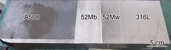
图 1
52M镍基合金异种金属焊接接头
Fig.1
Dissimilar metal welded joint (DMWJ) of the nickel base alloy 52M (52Mb—buttering material manufactured by 52M/ERNiCrFe-7A, 52Mw—weld material manufactured by 52M/ERNiCrFe-7A)
按照力学性能的不同,可将该DMWJ A508/52Mb界面附近区域分为热影响区(HAZ)、熔合区(FZ)和近界面区(NIZ) 3个区。并按照微观组织和硬度的分布将HAZ进一步细分为A、B、C和D 4个子区域,将NIZ进一步细分为F和G 2个子区域,FZ为单一的E区,如图2所示。
图2
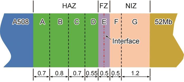
图2
A508/52Mb界面附近子区域的细分示意图
Fig.2
Schematic of different subareas near the A508/52Mb interface (HAZ—heat affected zone, FZ—fusion zone, NIZ—near interface zone; unit: mm)
1.2 试样设计
选用SENB试样对不同残余应力、不同拘束下DMWJ的断裂行为进行研究。SENB试样的取样与尺寸示意图如图3所示。SENB试样的宽度W = 14.4 mm,厚度B = 12 mm,跨距L = 57.6 mm (L = 4W),F为载荷,通过对试样上方加载辊施加向下6 mm的位移控制。在加载辊下压之前,分别在试样的左右两面、上下两面、前后两面、左右上下前后六面施加不同载荷(0、1、5、10、20、50、100和150 MPa)以在裂尖产生不同的应力,并通过restart方法,将该应力作为残余应力引入SENB试样。SENB试样的初始裂纹位于A508/52Mb界面位置,通过改变初始裂纹长度a (a / W = 0.2、0.3、0.5、0.6和0.7)得到不同的拘束。
图3
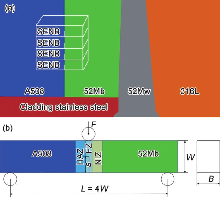
图3
SENB试样的取样与尺寸示意图
Fig.3
Schematics of sampling (a) and geometry (b) of the single edge-notched bend (SENB) specimen (a—crack depth, B—specimen thickness, W—specimen width, L—distance between the two support points, F—load)
1.3 残余应力的施加
在ABAQUS软件中,将建好的模型Model (即从1.1节中的DMWJ中提取1.2节中的SENB试样,并对SENB试样建立的模型)进行复制为Model-copy;分别在不同拘束试样模型Model的左右两面、上下两面、前后两面、左右上下前后六面施加不同载荷,通过有限元数值计算得到不同载荷下的裂尖应力场;通过软件中重启动(restart)的方法,将Model中得到的裂尖应力场作为残余应力导入Model-copy中(仅导入应力场而不导入应变场),从而实现Model-copy中残余应力的施加。
1.4 有限元数值计算
采用Gurson-Tvergaard-Needleman (GTN)损伤模型对不同拘束下DMWJ的断裂行为进行有限元数值计算。有限元数值计算分为2个步骤:在Model中预加载荷得到裂尖应力场、在Model-copy中加载辊下压得到断裂行为,典型加载分别如图4a和b所示。在第一步里,分别在试样的左右两面、上下两面、前后两面、左右上下前后六面施加不同大小的均布载荷(0、1、5、10、20、50、100和150 MPa),得到不同的应力场;通过restart重启动将该应力场作为残余应力导入模型后,在第二步里,通过对试样上方加载辊施加向下6 mm的位移控制载荷,得到不同残余应力、不同拘束下试样的载荷-位移曲线及每一加载步对应的裂纹扩展长度,并进一步计算得到DMWJ的J-R曲线。
图4

图4
有限元数值计算的2个步骤
Fig.4
Two steps of finite element numerical calculation (RP—reference point)
(a) crack tip stress fields are obtained by preloading
(b) fracture behavior is obtained by pressing down the loading roller
GTN损伤模型中包含9个参数:q1、q2、q3、f0、fN、εΝ、SN、fC和fF (其中,q1、q2和q3为本构参数;f0为初始孔洞体积分数;fN、εΝ和SN为孔洞形核参数;fC为孔洞开始聚合的临界孔洞体积分数;fF为失效孔洞体积分数)。该DMWJ的GTN参数已被准确标定,见文献[25]。
2 残余应力对不同拘束下DMWJ断裂行为的影响
2.1 左右两面加载对DMWJ断裂行为的影响
在不同拘束SENB试样的左右两面施加不同大小的均布载荷所得SENB试样的J-R曲线如图5所示。由图5可见,对于每一种具有不同拘束的SENB试样,随着预加载荷的增大,试样的J-R曲线均呈现出逐渐升高的趋势。在预加载荷较小时,J-R曲线的升高不明显;当预加载荷达到一定值时,J-R曲线迅速升高。但对于具有不同拘束的SENB试样,该值具有明显的不同。对于a / W = 0.2和0.3的低拘束试样,该值约为20 MPa,所对应的残余应力分别为65.777和93.241 MPa;对于a / W = 0.5、0.6和0.7的高拘束试样,该值明显减小。此外,在高拘束下,J-R曲线的变化幅度更加明显。2者都说明高拘束试样的J-R曲线对残余应力的变化更加敏感。当裂纹扩展长度为1 mm时,对于a / W = 0.2的低拘束试样,施加150 MPa预加载荷时所得到的J-R曲线比不加预加载荷时增加了43.92%;对于a / W = 0.7的高拘束试样,施加150 MPa预加载荷时所得到的J-R曲线比不加预加载荷时增加了141.00%。
图5
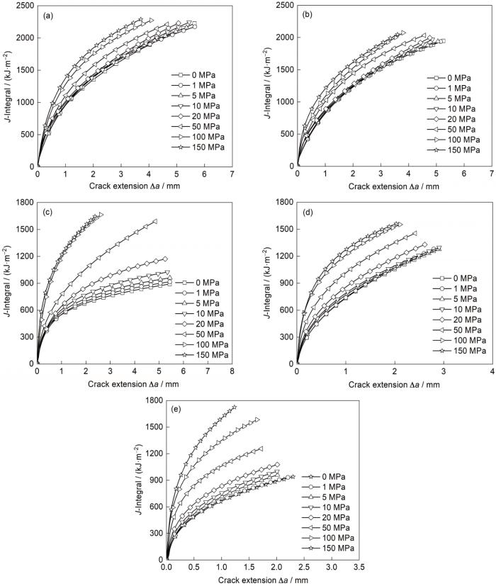
图5
左右两面加载时不同拘束SENB试样的J-R曲线
Fig.5
J-integral resistance (J-R)
(a) a / W = 0.2 (b) a / W = 0.3 (c) a / W = 0.5 (d) a / W = 0.6 (e) a / W = 0.7
为了深入分析预加载荷对不同拘束SENB试样J-R曲线的影响规律,提取不同载荷所引起的不同拘束试样裂尖的Mises应力,该应力在restart后将作为裂尖的残余应力,如图6所示。由图可见,随着预加载荷的增加,裂尖Mises应力呈现先缓慢增加、再迅速增加、最后缓慢增加的趋势,且随着拘束的增加(a / W的增加),裂尖Mises应力逐渐增加,这与图5中所呈现出的J-R曲线的变化规律一致。需要指出的是,此时裂尖三向应力均为压应力,如表1所示,当外加载荷为50 MPa时,可根据数值计算结果通过软件的查询功能直接查出a / W = 0.2低拘束试样在左右方向(即裂纹张开方向)所受压应力为250.336 MPa,在上下方向(即载荷方向)所受压应力为139.374 MPa;a / W = 0.7高拘束试样在左右方向所受压应力为648.487 MPa,在上下方向所受压应力为415.037 MPa。这也是图5中a / W = 0.7高拘束试样J-R曲线增加更多、变化更大的原因。
图6
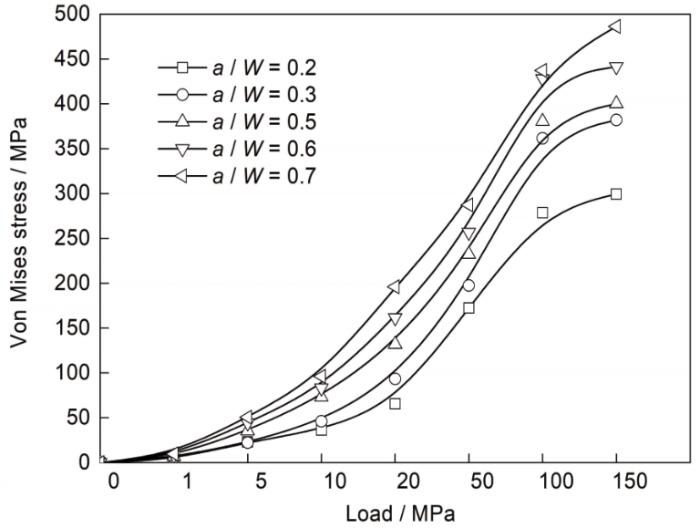
图6
不同载荷所引起的不同拘束试样裂尖的Mises应力
Fig.6
Crack tip Mises stress of specimens under different constraints caused by different loads
表1 不同面加载50 MPa时的裂尖三向应力 (MPa)
Table 1
| Loading direction | a / W = 0.2 | a / W = 0.7 | |||||
|---|---|---|---|---|---|---|---|
| S11 | S22 | S33 | S11 | S22 | S33 | ||
| Left and right sides | -250.336 | -101.749 | -139.374 | -648.487 | -413.334 | -415.037 | |
| Up and down sides | 51.294 | 22.198 | -16.065 | 74.558 | 32.180 | -20.025 | |
| Front and back sides | 14.327 | -43.509 | 8.306 | 6.344 | -46.679 | 3.897 | |
| Six sides | -297.622 | -170.190 | -212.761 | -715.665 | -365.400 | -481.419 | |
图7

图7
预加载荷为1 MPa时不同拘束试样的裂尖应力场
Fig.7
Crack tip stress fields of specimens with different constraints under 1 MPa (S, Mises—Von Mises stress)
(a) a / W = 0.2 (b) a / W = 0.3 (c) a / W = 0.5 (d) a / W = 0.6 (e) a / W = 0.7
2.2 上下两面加载对DMWJ断裂行为的影响
宽范围改变拘束,在a / W = 0.2和0.7时SENB试样的上下两面施加不同大小的均布载荷所得SENB试样的J-R曲线如图8所示。由图可见,随着预加载荷的增大,不同拘束SENB试样的J-R曲线呈现逐渐升高的趋势。与左右两面加载类似,在预加载荷较小时,J-R曲线的升高不明显;当预加载荷达到一定值时,J-R曲线迅速升高。但是与左右两面加载不同的是,无论是对于a / W = 0.2的低拘束试样,或是对于a / W = 0.7的高拘束试样,在不同预加载荷下,J-R曲线的变化幅度相近。当裂纹扩展长度为1 mm时,对于a / W = 0.2的低拘束试样,施加150 MPa预加载荷时所得到的J-R曲线比不加预加载荷时增加了18.24%;对于a / W = 0.7的高拘束试样,施加150 MPa预加载荷时所得到的J-R曲线比不加预加载荷时增加了19.34%,比a / W = 0.2低拘束试样略高。这与不同载荷所引起的裂尖Mises应力和三向应力有关,如图9和表1所示。
图8
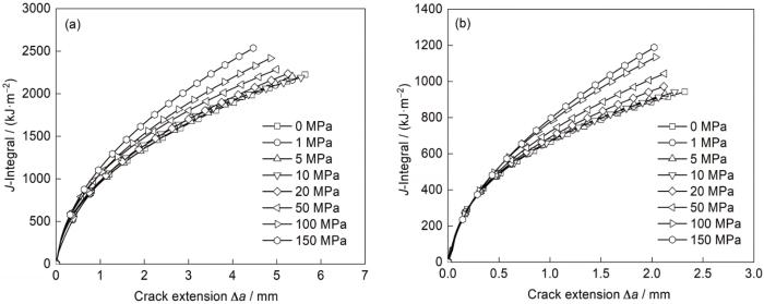
图8
上下两面加载时a / W = 0.2和0.7拘束SENB试样的J-R曲线
Fig.8
J-R curves of the SENB specimens with loading on the up and down sides under constraints of a / W = 0.2 (a) and 0.7 (b)
图9
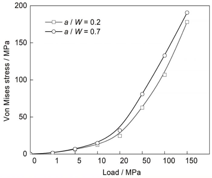
图9
不同载荷所引起的不同拘束试样裂尖的Mises应力
Fig.9
Crack tip Mises stress of specimens under different constraints caused by different loads
由图9可见,随着预加载荷的增加,虽然裂尖Mises应力都逐渐增加,但低拘束试样和高拘束试样之间相差不大,a / W = 0.7高拘束试样的裂尖Mises应力略高,这也是低拘束和高拘束试样J-R曲线增加幅度相近但a / W = 0.7高拘束试样增加略多的原因。表1示出了当外加载荷为50 MPa时的裂尖三向应力,同样可见,低拘束试样和高拘束试样裂尖三向应力相近,且在上下方向受压应力,在左右、前后方向受拉应力。前后方向的应力对J-R曲线影响不大,在上下方向压应力和左右方向拉应力的综合作用下,试样的J-R曲线略微增加但增加幅度不大。这也说明残余应力对不同拘束下DMWJ断裂行为的影响与残余应力的方向相关。因为J-R曲线在此时略微增加,结合上下方向压应力和左右方向拉应力的大小,可以发现对SENB试样而言,裂尖三向应力中上下方向应力对J-R曲线影响最大。
2.3 前后两面加载对DMWJ断裂行为的影响
宽范围改变拘束,在a / W = 0.2和0.7时SENB试样的前后两面施加不同大小的均布载荷,所得SENB试样的J-R曲线如图10所示。由图10可见,与左右两面、上下两面加载均不同,在前后两面加载时,随着预加载荷的增大,不同拘束SENB试样的J-R曲线在基本保持不变的基础上略有降低。通过对外加载荷为50 MPa时裂尖的三向应力状态进行考察发现,此时裂尖在前后方向受压应力,在左右和上下方向受拉应力,但拉应力均较小,如表1所示。对于SENB试样,前后方向的应力对J-R曲线影响不大,在左右和上下方向较小拉应力作用下,试样的J-R曲线呈现出在基本保持不变的基础上略微降低的变化趋势。对2种拘束试样裂尖Mises应力进行对比发现,不同预加载荷所引起的裂尖Mises应力基本一致(此处不再通过图片展示),这也是低拘束和高拘束下J-R曲线变化幅度相近的原因。
图10
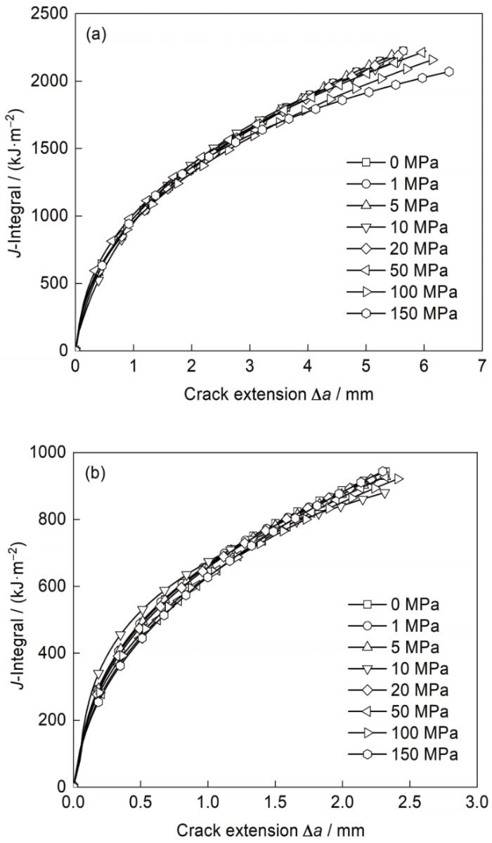
图10
前后两面加载时a / W = 0.2和0.7拘束SENB试样的J-R曲线
Fig.10
J-R curves of the SENB specimens with loading on the front and back sides under constraints of a / W = 0.2 (a) and 0.7 (b)
2.4 六面加载对DMWJ断裂行为的影响
宽范围改变拘束,在a / W = 0.2和0.7时SENB试样的左右上下前后六面同时施加不同大小的均布载荷,所得SENB试样的J-R曲线如图11所示。由图11可见,在左右上下前后六面加载时,随着预加载荷的增大,试样的J-R曲线呈现出逐渐升高的趋势。在预加载荷较小时,J-R曲线的升高不明显;当预加载荷达到一定值时,J-R曲线迅速升高;且对于a / W = 0.7高拘束试样,J-R曲线的变化更加明显。这些均与左右两面加载一致。当裂纹扩展长度为1 mm时,对于a / W = 0.2低拘束试样,施加150 MPa预加载荷时所得到的J-R曲线比不加预加载荷时增加了78.14%;对于a / W = 0.7高拘束试样,施加150 MPa预加载荷时所得到的J-R曲线比不加预加载荷时增加了242.66%。
图11
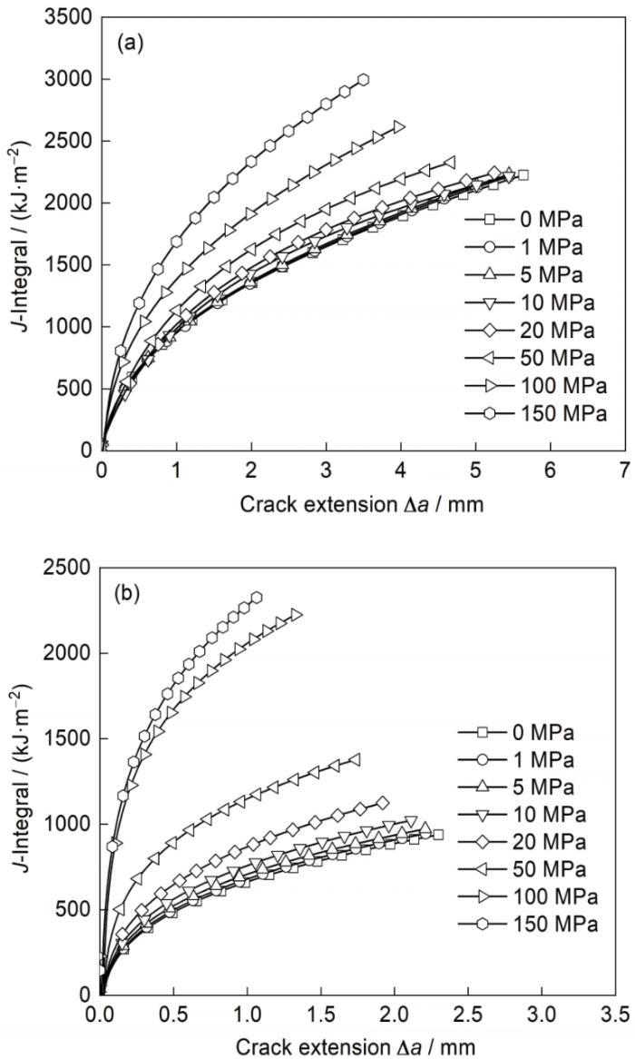
图11
六面加载时a / W = 0.2和0.7拘束SENB试样的J-R曲线
Fig.11
J-R curves of the SENB specimens with loading on the six sides under constraints of a / W = 0.2 (a) and 0.7 (b)
通过对2种拘束试样裂尖Mises应力进行对比发现,不同预加载荷所引起的裂尖Mises应力与左右两面加载时呈现的规律(图6)类似,随着拘束的增加,裂尖Mises应力逐渐增加,且六面加载比左右两面加载时整体偏高,这也是六面加载时试样J-R曲线更高的原因。且此时裂尖三向应力均为压应力,如表1所示。当外加载荷为50 MPa时,a / W = 0.2低拘束试样在左右方向所受压应力为297.622 MPa,在上下方向所受压应力为212.761 MPa;a / W = 0.7高拘束试样在左右方向所受压应力为715.665 MPa,在上下方向所受压应力为481.419 MPa。这也是图11中a / W = 0.7高拘束试样J-R曲线增加更多、变化更大的原因。
3 结论
(1) 残余压应力对于DMWJ J-R曲线的提高有着非常明显的促进作用。当裂纹扩展长度为1 mm时,a / W = 0.2低拘束试样J-R曲线最多增加了78.14%,a / W = 0.7高拘束试样J-R曲线最多增加了242.66%。
(2) 与低拘束试样相比,高拘束试样的J-R曲线对残余应力的变化更加敏感,这主要与裂尖Mises应力和三向应力有关。
(3) 残余应力对不同拘束下DMWJ J-R曲线的影响也与残余应力的方向相关。对于SENB试样,左右和上下方向的应力对J-R曲线影响较大,前后方向的应力对J-R曲线影响不大。
参考文献
Overview of reactor pressure vessel steel in PWR nuclear power plants
[J].
压水堆核电站反应堆压力容器材料概述
[J].
Stress corrosion cracking behavior of dissimilar metal weld A508/52M/316L in high temperature water environment
[J].
异材焊接件A508/52M/316L在高温水环境中的应力腐蚀破裂
[J].
Numerical simulations of specimen size and mismatch effects in ductile crack growth—Part I: Tearing resistance and crack growth paths
[J].
Numerical simulations of specimen size and mismatch effects in ductile crack growth—Part II: Near-tip stress fields
[J].
Effects of welded mechanical heterogeneity on interface crack propagation in dissimilar weld joints
[J].
Mechanical property variation within Inconel 82/182 dissimilar metal weld between low alloy steel and 316 stainless steel
[J].
An experimental investigation of in-plane constraint effect on local fracture resistance of a dissimilar metal welded joint
[J].
Out-of-plane constraint effect on local fracture resistance of a dissimilar metal welded joint
[J].
Fracture mechanism of cracks in the weakest location of dissimilar metal welded joint under the interaction effect of in-plane and out-of-plane constraints
[J].
Unified correlation of geometry and material constraints with fracture toughness of welded joint with high mismatch
[J].
几何和材料拘束与高匹配焊接接头断裂韧性的统一关联
[J].
Effects of strength mis-matching on the fracture behavior of nuclear pressure steel A508-III welded joint
[J].
Effect of material heterogeneity and constraint conditions on ductile fracture resistance of welded joint zones-Micromechanical assessment
[J].
Effect of welded mechanical heterogeneity on local stress and strain ahead of stationary and growing crack tips
[J].
Determination of inherent stresses by measuring deformations of drilled holes
[R].
Using local out-of-plane compression (LOPC) to study the effects of resxvidual stress on apparent fracture toughness
[J].
Effects of residual stress on creep damage and crack initiation in notched CT specimens of a Cr-Mo-V steel
[J].
Investigation of residual stress effects on creep crack initiation and growth using local out-of-plane compression
[J].
Effects of residual stress on creep crack initiation and growth of Cr-Mo-V steel in cracked C(T) specimen
[J].
Effect of residual stress on creep crack initiation and growth for specimens with different geometric and material constraints
[D].
残余应力对不同几何和材料拘束试样蠕变裂纹起裂和扩展行为的影响
[D].
Investigation of constraint and warm prestressing effects by means of a local approach to fracture
[J].
Residual stress induced crack tip constraint
[J].
Local mechanical properties and microstructures of Alloy 52M dissimilar metal welded joint between A508 ferritic steel and 316L stainless steel
[J].
Local mechanical properties of a dissimilar metal welded joint in nuclear powersystems
[J].
Effect and optimal design of the material constraint in the DMWJ of nuclear power plants
[J].
核电站DMWJ中材料拘束的影响与优化
[J].
