


在辐照环境下(如裂变和聚变反应堆中),载能粒子与材料相互作用过程中,当二者之间传递的能量超过原子的离位阈能时,会导致材料中原子移位形成自间隙缺陷,并在原来晶格点阵位置形成空位缺陷。当辐照过程中大量的载能粒子与材料相互作用时,即使空位与间隙子之间会发生湮灭反应,其剩余的空位和间隙子的浓度也远超过给定温度下的平衡态缺陷浓度,因此会形成过饱和的间隙子和空位缺陷。除了湮灭反应,这些间隙子与间隙子之间及空位与空位之间,也会同时发生团簇反应,形成间隙子团簇和空位团簇,随着辐照过程中团簇尺寸的增加,逐渐形成间隙型位错环和空洞,诱发材料辐照损伤,如辐照硬化、脆化、肿胀、蠕变及疲劳等[1~9] ,影响材料的服役性能,进而影响反应堆的安全运行及服役寿命,因此,对间隙型位错环和空洞等辐照缺陷的研究,一直是国内外核材料研究的热点之一[10~22]。在反应堆结构材料中,以bcc结构Fe为基的合金已经被广泛应用或者作为重要的候选材料。在这些合金中,经过长时间服役后,形成的间隙型位错环主要有2种:1/2<111>和<100>。其中<100>位错环在高温时占比较大,在低温时以1/2<111>为主[10~17]。这些位错环与其它缺陷之间发生不同的相互作用,对辐照损伤影响也不相同,例如,位错环与表面之间的相互作用不仅影响位错环的动力学过程,而且也影响材料表面辐照后的形貌[18]。
在辐照过程中,除了材料内部发生辐照损伤外,在材料的表面也会形成不同的辐照损伤,如表面肿胀、起皮及开裂等[1~5],同样严重影响材料的服役性能。随着反应堆中材料服役时间的延长,材料在辐照、热及力的作用下,可能会发生表面裂纹开裂,因此,在这些材料中形成的位错环可能会与微裂纹相互作用,形成新的缺陷及辐照损伤;同时,这些缺陷可能会与之前的辐照损伤相互叠加,对材料的服役性能产生新的影响,因此需要对位错环与微裂纹的相互作用机制进行深入系统研究。除了由表面开裂的裂纹外,在材料内部,随着辐照损伤的增加,同样也会造成材料内部微裂纹的形成,例如,由氦泡诱发的微裂纹的形成及扩展,是造成材料中氦脆的主要机制之一[6~9],这些由不同缺陷造成的微裂纹,在其扩展过程中,也可能与位错环相互作用,因此,同样需要研究材料内部的微裂纹与位错环相互作用的相关机制。
1 模型与方法
本工作主要研究在bcc结构Fe中在低温条件下常见的1/2<111>间隙位错环与微裂纹的相互作用过程。如上所述,在目前商用反应堆运行温度下(300 ℃左右),在铁基结构材料中,1/2<111>间隙位错环数密度比<100>位错环更高,同时,在此温度区间内,与辐照蠕变、疲劳及低温氦脆相关的辐照损伤都会导致材料中微裂纹的出现,因此,本工作首先对1/2<111>间隙位错环与微裂纹的相互作用过程开展研究。为了计算分析方便,计算胞的3个方向分别设定为X [111]、Y [
图1

图1
位错环与微裂纹相互作用模型示意图
Color online
Fig.1
Schematics of interaction between the interstitial dislocation loop and micro-crack (l—distance between dislocation loop and crack tip in Y direction, R—radius of dislocation loop, d—distance between dislocation loop and crack tip in X direction, P—the position of the crack tip, k—slope of crack, 2θ—crack tip opening angle)(a) crack is inside of the material(b) crack is from the free surface of material
2 结果及讨论
2.1 裂纹尖端位置的影响
本节主要模拟研究当位错环位于计算胞的中心位置时,通过改变裂纹尖端的位置,微裂纹与位错环之间的相互作用过程。
当d=1.5 nm、k=0.05、R=1.5 nm时,经过共轭梯度弛豫之后,微裂纹与位错环达到了局部平衡态。二者之间的相互作用如图2a所示,导致位错环在局部发生了弯曲。在此基础上开展在温度为300 K、压力为0 Pa的等温等压系综(NPT)下的分子动力学模拟,当计算模拟时间约3×10-13 s后,裂纹尖端两边的原子首先发生相互吸引作用,使得裂纹尖端上下两侧开始逐渐向裂纹中心运动,导致裂纹尖端尺寸逐渐减少;由于裂纹本身的存在,在没有外部其它原子补充的条件下,两侧原子的相互弛豫吸引并不能完全填充微裂纹本身,系统经过6×10-12 s弛豫后,如图2b所示,两侧原子的相互作用导致裂纹尖端往右移动,并在裂纹尖端初始位置处形成[010]位错线;同时,由于位错环与微裂纹之间的相互作用,导致部分位错环向微裂纹方向运动,形成不同惯习面组成的折线型位错环;再经过充分的分子动力学弛豫,1/2<111>位错环沿Burgers矢量方向向右运动,首先与形成的[010]位错线发生位错反应,并迅速与裂纹尖端产生相互作用,导致[010]位错线与位错环同时沿Burgers矢量方向向裂纹尖端运动,随着距离的减小,三者之间存在的相互作用逐渐变强,导致位错环中间部分被[010]位错线和裂纹尖端分别固定,形成位错网络,其中包含1/2<111>和<100>位错片段,如图2c所示;进一步分子动力学模拟发现,形成的位错网络,部分会逐渐被裂纹吸收,形成只含有<100>片段的位错网络,造成裂纹尖端再次向右运动,如图2d所示;随着时间的延长,位错网络与裂纹尖端继续反应,当时间达到约2.1×10-11 s时,如图2e所示,形成2个独立<100>位错片段,分别结束于裂纹两端,造成<100>位错线与裂纹尖端相互钉扎,形成稳定结构。
图2
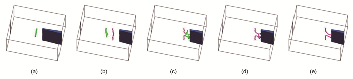
图2
位错环与裂纹尖端的水平距离(d)为1.5 nm、裂纹开裂斜率(k)为0.05、位错环半径(R)为1.5 nm时位错环与微裂纹相互作用的分子动力学演化过程
Color online
(a) results after the conjugate gradient method relaxation;(b~e) molecular dynamics simulation results at 300 K under 0 Pa pressure with time up to 6×10-12 s, 9.9×10⁻¹² s,1.7×10-11 s and 2.1×10⁻¹¹ s, respectively
Fig.2
Evolutions of the system with the interaction between the dislocation loop and micro-crack with d=1.5 nm, k=0.05 and R=1.5 nm
当微裂纹与位错环之间的距离增加,如d=3.2 nm而其它条件保持不变时,分子动力学模拟得到类似的结果,如图3所示。与上述结果的不同之处是位错环与[010]位错线相互接触反应,随着反应的进行,1/2<111>位错环完全被[010]位错线吸收,形成单独的[010]位错线,并与裂纹尖端的应力场在一定距离内达到平衡。
图3
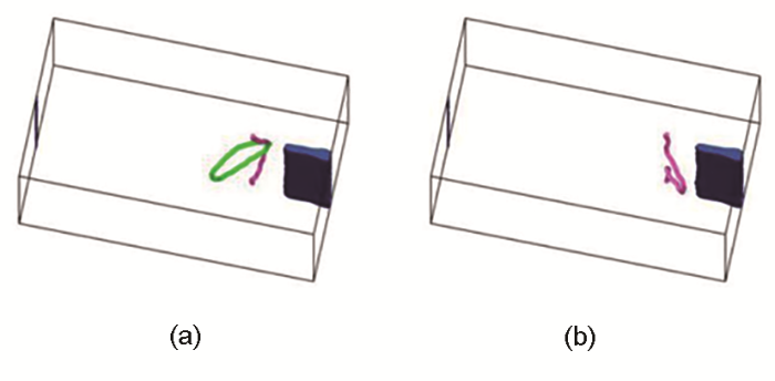
图3
d=3.2 nm、k=0.05、R=1.5 nm时位错环与微裂纹相互作用的分子动力学演化过程
Color online
(a) state when the loop and micro-crack start to contact with each other for further reaction;(b) equilibrium state between <010> dislocation and micro-crack after full relaxation
Fig.3
Evolutions of the system with the interaction between the dislocation loop and micro-crack with d=3.2 nm, k=0.05 and R=1.5 nm
当微裂纹与位错环之间的距离进一步增加,如d=4.5 nm而其它条件保持不变时,3×10-13 s后裂纹尖端两边的原子同样首先发生相互吸引作用,但是不同于上述裂纹尖端靠近位错环的情况,系统弛豫6×10-13 s后,如图4a所示,裂纹尖端同样向右移动,裂纹尖端初始位置形成的位错线是1/2[
图4
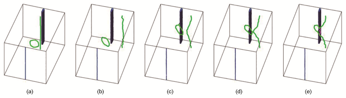
图4
d=4.5 nm、k=0.05、R=1.5 nm时位错环与微裂纹相互作用的分子动力学演化过程
Color online
Fig.4
Evolutions of the system with the interaction between the dislocation loop and micro-crack with d=4.5 nm, k=0.05 and R=1.5 nm(a) formation of 1/2[
综上可以看出,微裂纹尖端的位置对于位错环演化行为的影响很大,共同点是弛豫会造成裂纹尖端迅速相互吸引,形成位错线并导致裂纹尖端迁移;不同之处是,位错环与微裂纹尖端距离的不同导致裂纹尖端形成的位错线的性质不同,从而诱发了位错线与位错环及裂纹尖端之间的不同反应,导致最终或者形成2个独立位错线终结于裂纹表面;或者形成单根位错线与裂纹尖端稳定存在;或者形成包含1/2<111>和<111>的位错网络与裂纹尖端共存结构,使得最初的位错环不能被裂纹吸收,而形成复杂的辐照缺陷结构。
2.2 裂纹开裂斜率的影响
d=1.5 nm、R=1.5 nm、k=0.05时位错环与裂纹尖端相互作用过程如图2所示。当开裂斜率增加,如k=0.10时,相同条件下系统经过3×10-12 s弛豫后,裂纹尖端两边的原子才明显发生相互吸引,随后在裂纹尖端逐渐形成多个<100>位错线段,当这些<100>位错线段相互反应后,部分演化为1/2<111>位错线段,导致在裂纹尖端形成<100>和1/2<111>位错线段共存的位错网络,而裂纹尖端位置不随这些位错线段的出现及反应而发生迁移,位错环此时也没有与裂纹尖端相互接触,形成的结构如图5a所示。随着反应时间的延长,在5.1×10-12 s时,位错环到达裂纹尖端附近,裂纹尖端位错线开始与位错环发生反应,从而使得位错环部分与位错线反应,部分形成两端终结于裂纹表面的位错线,其Burgers矢量为1/2[111],进一步的模拟表明,此位错线可以在裂纹表面沿其Burgers矢量方向向右运动,如图5b所示。直到2.55×10-11 s时位错环完全被吸收,7.23×10-11 s 后只有少量位错线片段留在材料内部,如图5c所示。因此,不同于k=0.05的情况,当裂纹开裂斜率增加时,裂纹尖端形成的位错线不会诱发尖端位置的变化,而形成的两端终结于裂纹表面的位错线,则在裂纹表面沿Burgers矢量方向运动,最终被裂纹吸收。
图5
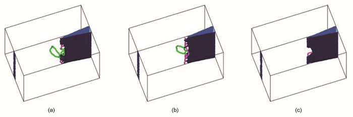
图5
d=1.5 nm、R=1.5 nm、k=0.10时位错环与微裂纹相互作用的分子动力学演化过程
Color online
(a) formation of <100> and 1/2<111> dislocation network at the tip of micro-crack after the initial relaxation;(b) state of dislocations which end on the surface of the micro-crack after directly reacting with the micro-crack tip;(c) final state with one dislocation segment located at the tip of micro-crack after the loop has been fully absorbed by micro-crack
Fig.5
Evolutions of the system with the interaction between the dislocation loop and micro-crack with d=1.5 nm, R=1.5 nm and k=0.10
当裂纹尖端开裂斜率进一步增加时,如k=0.15时,在其它条件不变的情况下,裂纹尖端在弛豫后没有形成<100>或1/2<111>的位错线段,当时间达到4.8×10-12 s时,如图6a所示,位错环与裂纹接触发生反应;当时间为5.4×10⁻¹² s时,如图6b所示,在位错环与裂纹尖端相互反应区域形成<100>位错线段,从而构成<100>和1/2<111>共存的位错网络;当时间为6.9×10-12 s时,如图6c所示,二者的相互作用形成两端终结于裂纹表面的1/2[111]位错线,两端终结于对称裂纹表面的[100]位错线以及在裂纹尖端剩余的<100>位错线段;与上述情形相同,终结于裂纹表面的位错线沿着Burgers矢量方向运动,9×10-12 s时两端终结于对称裂纹表面[010]位错线先被吸收,1.26×10-11 s时1/2[111]位错线及裂纹尖端的[100]位错线完全被吸收,形成裂纹尖端凸凹不平的结构,如图6d所示,之后尖端处不断形成<100>、随即吸收再形成,以此反复处于一种动态平衡状态。
图6
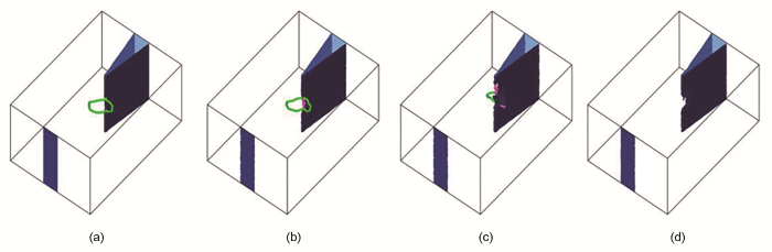
图6
d=1.5 nm、R=1.5 nm、k=0.15时位错环与微裂纹相互作用的分子动力学演化过程
Color online
(a) initial state when the loop and micro-crack start to contact with each other for further reaction;(b) formation of dislocation network after the formation of <100> and 1/2<111> segments;(c) state of 1/2<111>dislocation which ends on the surface of micro-crack after the initial relaxation and <100> dislocation located at the tip of micro-crack;(d) final rugged tip after the dislocation loop has been absorbed by micro-crack
Fig.6
Evolutions of the system with the interaction between the dislocation loop and micro-crack with d=1.5 nm, R=1.5 nm and k=0.15
当开裂斜率增加到k≥0.20时,位错环与裂纹接触发生反应,首先形成两端终结于裂纹表面的1/2[111]和[010]位错线,分别位于裂纹两侧,7.5×10-12 s时[010]位错线片段被吸收,10.2×10-12 s时1/2[111]被吸收,裂纹尖端凸凹不平,如图7所示。
图7
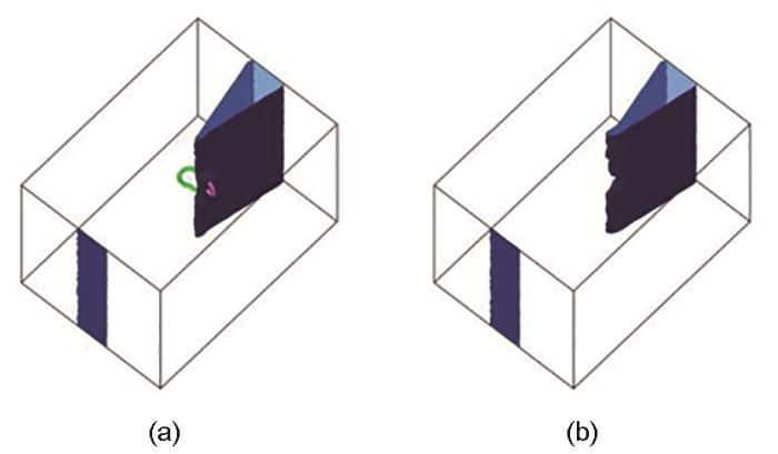
图7
d=1.5 nm、R=1.5 nm、k≥0.20时位错环与微裂纹相互作用的分子动力学结果演化过程
Color online
(a) formation of <100> and 1/2<111> segments which both end on the surface of micro-crack;(b) final rugged tip after the dislocation loop has been absorbed by micro-crack
Fig.7
Evolutions of the system with the interaction between the dislocation loop and micro-crack with d=1.5 nm, R=1.5 nm and k≥0.20
当位错环和裂纹尖端距离增加时,如d=3.2和4.5 nm时,随着k的增加,同样会导致上述类似反应的发生。除此以外,模拟结果还发现在d=3.2和4.5 nm,k=0.10的情况下,会使得裂纹尖端形成的位错片段和裂纹本身的应力场叠加,对位错环产生排斥作用,使得位错环远离位错尖端,这种情况出现几率比较小,如图8所示。
图8
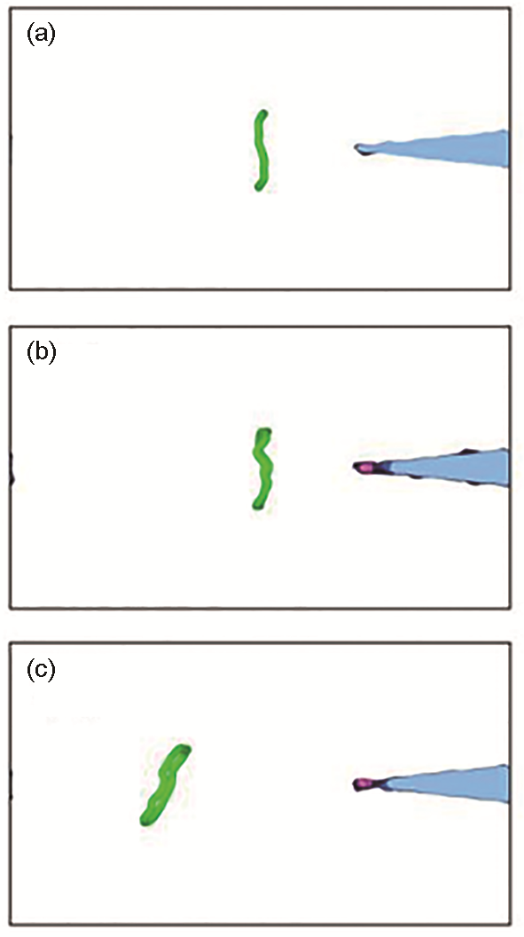
图8
d=3.2 nm、R=1.5 nm、k=0.10时位错环与微裂纹相互反应过程中,位错环与微裂纹表现为相互排斥导致位错环远离微裂纹的演化过程
Color online
Fig.8
Evolutions of dislocation loop and micro-crack with the repulsive interaction between them with d=3.2 nm, R=1.5 nm and k=0.10 (The distance between them increases with simulation time (t))(a) t=1.5×10⁻¹² s(b) t=4.8×10⁻¹² s(c) t=7.5×10⁻¹¹ s
相同条件下,还计算了温度为600 K时的情况,在d=1.5、3.2 和4.5 nm,以及k=0.05、0.10、0.15、0.20、0.25时均得到与300 K相类似的相互作用过程和结果,本文不再赘述。需要说明的是,当d=4.5 nm、k=0.05时,在1/2<111>位错线与裂纹不断反应过程中,裂纹出现了先部分被吸收而后又形成的现象。
2.3 位错环与裂纹尖端相对位置和距离的影响
当位错环与微裂纹相互作用时,除了位错环中心位于裂纹对称面的理想情形外,还有其它可能的情况,例如位错环中心位于微裂纹尖端的周围而与其发生相互作用。本工作通过改变位错环的位置,对其进行了研究。
当位错环与裂纹尖端均位于裂纹对称面时,如R=1.5 nm、l=1.5 nm,当d=1.5 nm、k=0.05时,分子动力学模拟发现,位错环与裂纹尖端存在相互吸引作用,导致位错环沿Burgers矢量方向向裂纹方向运动,裂纹尖端在此过程中也通过弛豫形成1/2<111>位错线片段,然后沿裂纹由中心向两边扩展,形成贯通裂纹尖端的位错线;当位错环运动一定距离后,与1/2<111>位错线发生相互作用,形成位错网络,其中包含<100>片段和1/2<111>片段,贯通尖端的位错网络逐渐脱离裂纹,裂纹尺寸缩小,由于<100>片段的钉扎作用,形成的位错网络无法运动,不能被裂纹尖端吸收,最终形成裂纹、<100>、1/2<111>位错网络共存的缺陷结构,与图4e所示结果类似,此处不再重复。
除了上述相互作用过程外,位错环与裂纹尖端相对位置改变后的相互作用同样受到d的影响。例如当d=3.2 nm、l=1.5 nm、k=0.05时,在其它条件相同的情况下,裂纹尖端与位错环相互吸引,在裂纹尖端形成贯通的1/2<111>位错线,之后位错环沿Burgers矢量方向向右运动,而形成的1/2<111>位错线沿其Burgers矢量方向向[$11\bar{1}$]方向运动,当位错环、位错线之间的距离达到一定值后,二者与裂纹尖端之间相互作用达到平衡态,导致位错环和位错线均不再运动,形成位错线、位错环和裂纹尖端共存的缺陷结构。进一步模拟发现,当d≥3.2 nm时,改变l的大小,最后均形成相同的位错线、位错环和裂纹尖端共存的稳定结构。这些结果可以对微裂纹尖端出现的位错及辐照位错环耗尽区域的出现做出合理的解释[35]。
2.4 位错环尺寸及自由表面的影响
除了上述影响因素外,位错环本身的尺寸也是可能影响位错环与裂纹尖端相互作用的影响因素之一。当二者之间的距离固定后,如d=1.5 nm、k=0.05且位错环位于计算胞中心,R=1.5 nm的情况在前文已经详细描述,当R=2.0和3.0 nm时,计算模拟得到了类似的反应过程:位错环与裂纹尖端弛豫形成的位错线相互作用,最终被全部吸收或者得到位错片段与裂纹共存的结构。当k增加后,如k=0.10,当R=1.5 nm时,得到上述类似结果,但是随着R的增加,模拟也得到了位错环、位错线和裂纹尖端共存的结构。当k增加到0.15、0.20和0.25后,得到的结果均已在上述模拟结果中,此处不再赘述。
裂纹在材料内部的情况前文已经详细介绍,对于形成于自由表面的微裂纹与位错环的相互作用过程及相应的机制,二者的相互作用模型如图1b所示。计算模拟结果表明,自由表面的存在对二者的相互作用影响很小,如裂纹尖端与位错环同样首先相互吸引,在弛豫过程中,裂纹尖端形成位错线,位错环沿Burgers矢量方向向位错线及裂纹尖端靠近,首先与位错线反应,之后二者反应后的位错网络与裂纹尖端相互作用,随着k改变,形成了位错线和裂纹尖端共存的结构或者位错环被完全吸收的结构,这些结果在前文已经做了详细的阐述。通过对这些过程的分析发现,自由表面的存在对裂纹的影响甚微,但是对位错环的影响比较显著,在k≥0.10时,表面的存在加速了位错环的吸收,如表1所示,在相同的反应条件下,从有无表面存在时位错环被吸收所用的时间变化情况可以清楚地看到,表面应力场的存在,对1/2<111>位错环的运动具有明显的加速效应,增加了位错环被吸收的几率。其1/2<111>位错环与自由表面相应的作用机制,已在文献[36]中做了详细的描述,此处也不再赘述。
表1 d=15 nm时不同R和k下,有无自由表面位错环被完全吸收所用的模拟时间
Table 1
| k | R=1.5 nm | R=2.0 nm | R=3.0 nm | |||
|---|---|---|---|---|---|---|
| Inside of bulk | Free surface | Inside of bulk | Free surface | Inside of bulk | Free surface | |
| 0.05 | 11.7 | 11.4 | 11.4 | 12.3 | 14.7 | 24.3 |
| 0.10 | 25.2 | 16.5 | Unabsorbed | 16.2 | Unabsorbed | 21.6 |
| 0.15 | 12.6 | 12.6 | 15.9 | 14.7 | Unabsorbed | 18.9 |
| 0.20 | 10.5 | 9.9 | 17.7 | 15.0 | Unabsorbed | 15.6 |
| 0.25 | 8.1 | 7.5 | 10.5 | 10.5 | 14.4 | 17.7 |
3 结论
对间隙型位错环与微裂纹之间的相互作用,在一定条件下,可以形成位错环、位错线及微裂纹共存的辐照缺陷结构,二者之间的相互作用也可以导致位错环被微裂纹完全吸收。另外,微裂纹尖端与位错环之间的相对位置及裂纹开裂斜率的变化,对位错环演化行为的影响较大,导致裂纹尖端形成的位错线性质不同,位错环及裂纹尖端之间的反应也不相同;而自由表面的存在,对位错环的影响比较显著,可以加速位错环被裂纹吸收的过程。所有这些结果都清晰地表明,辐照形成的间隙型位错环与微裂纹的相互作用,会形成复杂的辐照缺陷结构、微裂纹被吸收或者造成裂纹尖端凹凸不平,这些结构均会对微裂纹的开裂及扩展产生影响,造成材料在辐照条件下力学性能的退化。因此,在未来抗辐照材料的研发过程中,需要考虑位错环与微裂纹相互作用对材料辐照损伤性能的影响。
参考文献
Swelling and structure of radiation induced near-surface damage in CR-39 and its chemical etching
[J].
A comparative study of swelling, strain and radiation damage of high-energy proton-bombarded GaAs, GaP, InP, Si and Ge single crystals
[J].
Swelling, strain, and radiation damage of He+ implanted GaP
[J].
Inhibition of radiation blistering in tin bombarded by protons and alpha particles
[J].
Low-activation ferritic and martensitic steels for fusion application
[J].
Radiation effects in structural materials of spallation targets
[J].
Radiation damage tolerant nanomaterials
[J].
The effect of He+ irradiation on hardness and elastic modulus of Fe-Cr-40 wt.% TiB2 composite rod designed for neutron absorbing
[J].
Evaluation of irradiation hardening and microstructure evolution under the synergistic interaction of He and subsequent Fe ions irradiation in CLAM steel
[J].
Heavy-ion irradiations of Fe and Fe-Cr model alloys Part 1: Damage evolution in thin-foils at lower doses
[J].
Effect of the α-γ phase transition on the stability of dislocation loops in bcc iron
[J].
Body-centered-cubic iron develops an elastic instability, driven by spin fluctuations, near the alpha-gamma phase transition temperature T(c) = 912 degrees C that is associated with the dramatic reduction of the shear stiffness constant c' (c(11)-c(12))/2 near T(c). This reduction of c' has a profound effect on the temperature dependence of the anisotropic elastic self-energies of dislocations in iron. It also affects the relative stability of the a[100] and a/2[111] prismatic edge dislocation loops formed during irradiation. The difference between the anisotropic elastic free energies provides the fundamental explanation for the observed dominant occurrence of the a[100], as opposed to the a/2[111], Burgers vector configurations of prismatic dislocation loops in iron and iron-based alloys at high temperatures.
Heavy-ion irradiations of Fe and Fe-Cr model alloys Part 2: Damage evolution in thin-foils at higher doses
[J].
Dynamic observations of heavy-ion damage in Fe and Fe-Cr alloys
[J].
The temperature dependence of heavy-ion damage in iron: A microstructural transition at elevated temperatures
[J].
Comparison between bulk and thin foil ion irradiation of ultra high purity Fe
[J].
Changes in the Burgers vector of perfect dislocation loops without contact with the external dislocations
[J].
Surface effect on <100> interstitial dislocation loop in iron
[J].
表面效应对铁<100>间隙型位错环的影响
[J].
The type identification of dislocation loops by TEM and the loop formation in pure Fe implanted with H+
[J].
利用透射电镜衬度像变化判定位错环类型及注氢纯铁中形成的位错环分析
[J].本文分两部分,第一部分研究了利用透射电镜衬度像变化判定材料中位错环类型的方法,即采用所谓inside-outside方法来判断位错环为空位型位错环或间隙型位错环. 第二部分讨论了加速器注氢纯铁在673—773 K时效后形成的位错环的类型.
Effects of helium and deuterium on irradiation damage in pure iron
[J].
氦、氘对纯铁辐照缺陷的影响
[J].
Characterization of dislocation loops in hydrogen ion-implanted Fe-Cr alloy annealed at different temperatures
[J].
室温注氢Fe-Cr合金在不同温度退火后位错环的表征
[J].
Characterization of dislocation loops in hydrogen-ion irradiated vanadium
[J].
氢离子辐照纯钒中形成的位错环
[J].
Review of irradiation assisted stress corrosion cracking of core structural materials
[J].
堆芯结构材料辐照促进应力腐蚀开裂研究现状
[J].
Static and dynamic multipolar field expansions of dislocations and cracks in solids
[J].
Characterization of ion irradiation effects on the microstructure, hardness, deformation and crack initiation behavior of austenitic stainless steel: Heavy ions vs protons
[J].
Molecular dynamics simulation of crack tip processes in alpha-iron and copper
[J].
A new fatigue-creep life prediction methodology
[J].
基于微裂纹扩展的疲劳蠕变寿命预测方法
[J].
Fatigue crack deflection and formation of microcracks in porosity area of ZG42CrMo
[J].
ZG42CrMo缩松区疲劳裂纹的偏析和微裂纹的形成
[J].测定了ZG42CrMo高周疲劳裂纹扩展速率,对疲劳裂纹扩展过程进行了金相追踪观察.用EPM研究了缩松及其表面微裂纹和硫化物的形态.用TEM研究了裂纹顶端位错组态和滑移特征.讨论了缩松对裂纹捕获和偏折对疲劳裂纹扩展的双重影响及微裂纹萌生的可能机制.
Formation and development of shear deformation localization in low carbon steel
[J].
钢中剪切变形局部化的形成与发展
[J].
TEM in situ observation of brittle cracking of hydrogen charged 310 stainless steel under tension
[J].The effect of hydrogen on the cracking of type 310 stainless steel was studied by TEM in situ observation of hydrogen-charged specimens and comparison with the hydrogen-free specimens.The results show that 1)in precharged specimens,many dislocations can emit from a crack tip followed by forming a dislocation free zone(DFZ) after equilibrium:2)nanocracks nucleate preferable in DFZs;3)microcracks connect with each other,resulting in the brittle cracks,instead of blunting into voids.The effect of hydrogen on the change from ductile to brittle is to prevent nanocracks in DFZs from blunting into voids.
氢致脆断的TEM原位拉伸观察
[J].通过对预充氢310不锈钢薄膜在透射电镜(TEM)下的原位拉伸观察,并和不含氢试样的结果相比较,研究了氢在韧-脆转变中的作用及氢致脆断机理.结果表明,预充氢的310不锈钢试样在拉伸过程中从裂尖发射大量位错,平衡后形成无位错区(DFZ);纳米级微裂纹择优在DFZ中形核;微裂纹不钝化为空洞,而是通过多个微裂纹的形核及相互连接导致裂纹的脆性扩展.即氢使奥氏体不锈钢由韧变脆的根本原因是氢抑制了DFZ中纳米级微裂纹向空洞的转化.
Development of an interatomic potential for phosphorus impurities in α-iron
[J].
Development of new interatomic potentials appropriate for crystalline and liquid iron
[J].
Fast parallel algorithms for short-range molecular dynamics
[J].
Extracting dislocations and non-dislocation crystal defects from atomistic simulation data
[J].
HVEM observation of dislocation-free zones at crack tips in iron single crystals
[J].
Interactions of prismatic dislocation loops with free surfaces in thin foils of body-centered cubic iron
[J].
