



高强度与高导电性的双重优势,使得金属纤维增强的bcc结构铜基复合材料在电子电气工程领域展现出巨大应用潜力[1]。这类材料已广泛应用于特种电极、集成电路引线框架、承重电缆等产品的制造。其中,Cu-Fe合金体系因Fe元素成本显著低于Nb、Cr、Ag等其他bcc结构金属而备受关注[2,3]。然而,Cu-Fe复合材料的导电性能普遍低于其他铜基材料,这主要归因于高温下Fe元素在Cu中的高固溶度,以及低温下Fe析出动力学缓慢[4]。固溶于Cu基体中的Fe原子对电导率损害显著(约9.2 μΩ⋅cm/%)[5]。因此,如何在不降低强度的前提下,有效降低Cu基体中固溶的Fe含量以提高Cu-Fe复合材料的导电性能,成为当前研究的重点。
传统Cu-Fe复合材料的制备通常采用铸造结合高强度机械加工的工艺路线。凝固过程中首先生成Fe枝晶,随后通过拉拔[6]、轧制[7]、等通道角挤压[8]等机械加工工艺将其转化为纤维结构。研究[9~11]表明,开发三元Cu-Fe-X复合材料可协同提升传统二元合金的强度与导电性能。例如,Chen等[12]在Cu-10Fe (质量分数,%,下同)合金中添加0.2%Mg (质量分数),并采用多级热机械加工工艺,成功制备出具有超细CuMg2纳米析出相(粒径约6.8 nm)嵌入Cu纳米层状基体的原位复合材料,与采用相同工艺制备的Cu-10Fe合金相比,强度提升约23% (达到1239 MPa),同时保持96%的导电性能(51.1%IACS)和相当的均匀延伸率。力学性能的提升主要归因于引入的纳米析出相产生了Orowan强化效应及其对加工硬化的促进作用。添加Ag、Nb及稀土元素也具有类似Mg元素的有益作用[9~11]。然而,添加Co、Cr、Ni等元素对材料性能的改善效果有限,甚至可能产生负面影响[13]。
本工作采用冷喷涂结合热处理与冷轧工艺,构建了具有细长Cu晶粒、Fe纤维和高位错密度的微观结构,使Cu-10Fe原位复合材料获得了优异的抗拉强度和高电导率。利用多尺度的微观结构表征,揭示了其微观结构演变规律,并讨论了材料的强化及导电机制,为高性能Cu-Fe复合材料的大规模生产提供一些新的见解。
1 实验方法
1.1 样品制备
采用气体雾化球形Cu粉末和Fe粉末作为原料。将Cu粉和Fe粉按照质量比9∶1在GH-5L混料机中机械混合,作为冷喷涂的原料。采用尺寸为100 mm × 200 mm × 10 mm的纯Al板作为基材,基材用砂纸研磨,然后用乙醇清洗、烘干。采用PCS-1000高压冷喷涂系统在Al基体上制备Cu-10Fe沉积体。在冷喷涂过程中,采用加压N2 (5 MPa、700 ℃)作为推进气体,喷涂距离为20 mm,喷涂角度为90°,喷嘴横向移动速率为200 mm/s,喷涂完成后采用线切割将冷喷涂Cu-10Fe沉积体从Al基材上切割下来,得到尺寸为50 mm × 50 mm × 10 mm的Cu-10Fe沉积体。采用线切割将冷喷涂Cu-10Fe沉积体切成尺寸为50 mm × 10 mm × 10 mm的长方体并用石英管密封,石英管内真空度为9 × 10⁻³ Pa以下,将密封石英管放入预先升温至600 ℃的马弗炉中热处理24 h,之后空冷至室温。然后,在室温下采用辊径为140 mm的ZK-W615-1二辊轧机对热处理后的Cu-10Fe沉积体进行多道次冷轧,轧速为10 r/min,每道次压下率(η)为10%~30%,压下率的计算公式为:
式中,δ0和δ1分别为样品轧制前后的厚度。计算结果表明,沉积体最终的压下率为99%。
1.2 微观结构表征
利用EVO-18扫描电子显微镜(SEM)对Cu粉和Fe粉的微观结构进行表征。采用Malvern Panalytical Mastersizer 3000激光粒径分析仪对Cu粉和Fe粉的粒径进行分析。采用线切割从Cu-10Fe沉积体中沿沉积方向切割横截面样品,经过研磨和抛光后,利用EVO-18 SEM和Nordlys Max3电子背散射衍射仪(EBSD)获得微观结构信息。用于EBSD观察的样品首先经过研磨、抛光,然后在Buehler Vibromet 2振动抛光机上用Mastermet抛光剂(磨料为0.06 μm胶体SiO2)进行振动抛光。EBSD在20 kV电压下,以25 nm的步长扫横截面,并使用Channel 5软件对记录的数据进行后处理。采用Crossbeam Auriga聚焦离子束扫描电镜(FIB-SEM)找到Fe纤维所在区域并切下透射样品,利用Talos F200X G2透射电子显微镜(TEM)及其附带的能谱仪(EDS)获得相界面的微观结构信息。采用Nexsa X射线衍射仪(XRD)表征和量化沉积体的相组成,工作电压40 kV、电流40 mA、扫描步长0.005°、每步驻留时间为0.1 s。利用EVO-18 SEM和Image J软件对冷喷涂沉积体中的孔隙率进行测量。
1.3 电导率和力学性能测定
在沉积条件、热处理条件和冷轧条件下评价Cu-10Fe沉积体的电导率和力学性能。采用ZY9987型数字式微欧计测量合金的电导率。每个样品重复测量三次,然后求其平均值。采用国际退火铜标准计算合金的电导率,计算公式为[27]:
式中,W为电导率,R为电阻,L为测量点之间的距离,S为合金导线的横截面面积。
采用线切割从平行于沉积体表面的平面上切割狗骨头状拉伸样品,其中平行段尺寸为25 mm × 3 mm × 0.1 mm。拉伸实验在25 ℃下进行,应变速率为5 × 10⁻³ s-1。利用配有光学引伸计的CMT5205电子万能试验机获得应力-应变曲线。每组样品分别测试三次。
2 实验结果
2.1 原始粉末微观结构表征
图1为Cu粉和Fe粉微观形貌的SEM像和粒径分布。可以看出,Cu粉和Fe粉呈球形,少量的细粉颗粒以卫星颗粒的形式附着在粗粉颗粒上。根据粉末的粒径分布可知,大部分粉末颗粒在20~80 µm的尺寸范围内,Cu粉和Fe粉的体积平均粒径分别为37.7和40.4 μm。分别用D10、D50 和 D90代表Cu粉末中累计体积分布达到10%、50%和90%时对应的直径,则Cu粉末的D10、D50 和 D90分别为19.5、35.6和59.0 µm,Fe粉的D10、D50 和 D90分别为 27.6、39.1和55.4 µm。
图1
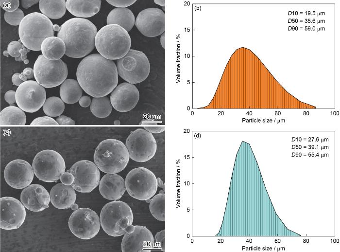
图1
Cu粉和Fe粉微观形貌的SEM像和粒径分布
Fig.1
SEM images (a, c) and particle size distributions (b, d) of Cu powder (a, b) and Fe powder (c, d) (D10—volume 10th percentile diameter, D50—volume median diameter, D90—volume 90th percentile diameter)
2.2 微观结构
冷喷涂(CS)、热处理(HT)和热处理-冷轧(HTCR)态Cu-10Fe样品横截面微观组织的SEM像如图2所示。虽然冷喷涂Cu-10Fe沉积体的大部分区域都呈现致密结构,但由于机械耦合的不均匀性,可以观察到一定数量的孔隙,且存在界面结合不良的现象,如图2a所示。由于冷喷涂Cu-Fe沉积体延展性较差,轧制过程中边缘发生不均匀变形,易产生边缘裂纹,因此,需先进行热处理以便后续冷轧。经过热处理后,HT态沉积体样品的孔隙增多,沉积颗粒间的界面结合减弱,尤其是Cu/Fe沉积颗粒间的界面明显变差,如图2b所示。在经历严重的轧制变形后,HTCR态样品中微米级沉积颗粒沿轧制方向伸长,沉积颗粒间的孔隙和界面结合不良的问题得到改善,孔隙完全消失,如图2c和d所示。孔隙率定量测量结果表明,CS、HT和HTCR态Cu-10Fe样品的孔隙率分别为0.13%、0.86%和0.09%,如图3所示。与Fe相比,Cu是一种相对软的材料,在Cu中加入坚硬的Fe颗粒,可以在喷涂过程中起到原位喷丸效应[28,29],从而导致冷喷涂沉积体中额外的塑性变形和较低的孔隙率。经热处理-冷轧后,沉积体的孔隙密度进一步降低,证实了热处理-冷轧后处理对降低冷喷涂Cu-10Fe沉积体的孔隙率是有效的。
图2
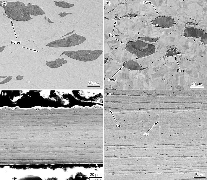
图2
冷喷涂、热处理和热处理-冷轧Cu-10Fe样品横截面微观组织的SEM像
Fig.2
Cross-sectional SEM images of Cu-10Fe samples after cold spray (CS) (a), heat treatment (HT) (b), and heat treatment and cold rolling (HTCR) (c, d)
图3
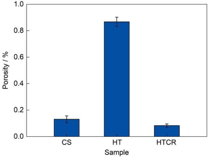
图3
冷喷涂、热处理和热处理-冷轧Cu-10Fe样品的孔隙率
Fig.3
Porosities of Cu-10Fe samples after CS, HT, and HTCR
图4为CS、HT和HTCR态Cu-10Fe样品横截面的EBSD表征结果。对于CS态Cu-10Fe样品,从图4a1的反极图(IPF)可以看出,冷喷涂Cu-10Fe沉积体的晶粒取向为随机的,且该沉积体具有梯度纳米晶结构:超细纳米Cu晶粒围绕着微米级变形Fe晶粒和较为粗大的微米级Cu晶粒,其中超细纳米Cu晶粒尺寸为80~800 nm,微米级Cu晶粒尺寸为1.5~10.0 μm,微米级Fe晶粒尺寸为3.5~10.0 μm。这种双峰结构可归因于喷涂颗粒沉积过程中的非均匀变形,在颗粒/颗粒界面上产生了大量超细纳米晶粒,界面区域的超细纳米晶粒很可能是由于动态再结晶形成的[30,31]。图4a2和a3分别为相分布图和局部取向差(KAM)图。KAM图表明,沉积体中的应变主要集中于Cu沉积颗粒与Fe沉积颗粒的相界面处,而Fe沉积颗粒内部的应变明显低于界面,表明塑性变形局限于Fe沉积颗粒外围[32,33]。此外,Cu沉积颗粒中的应变积累明显多于Fe沉积颗粒,Cu沉积颗粒的平均KAM值为1.32°,而Fe沉积颗粒为1.08°,混合粉末在冷喷涂过程中的塑性变形主要集中于较软侧,而硬侧的变形则相对有限[34]。从图4a4的晶界图可以看出,小角度晶界(LAGB)与图4a3中较高的位错密度吻合。
图4
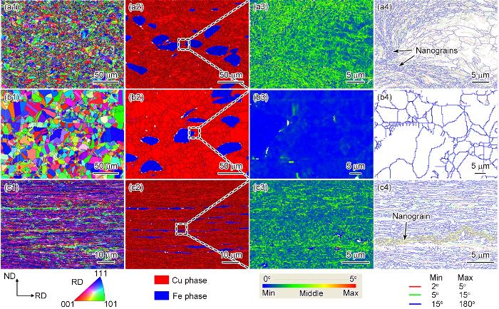
图4
冷喷涂、热处理和热处理-冷轧Cu-10Fe样品横截面的EBSD表征
Fig.4
EBSD characterizations of cross section of Cu-10Fe samples after CS (a1-a4), HT (b1-b4), and HTCR (c1-c4) (ND—normal direction, RD—rolling direction)
(a1-c1) inverse pole figures (IPFs) (a2-c2) phase distribution images (a3-c3) kernel average misorientation (KAM) maps (a4-c4) grain boundary images
Cu-10Fe沉积体经冷轧后的EBSD分析如图4c1~c4所示。可以看出,经大变形量的冷轧后,材料的微观结构发生了显著变化:等轴晶粒沿轧制方向伸长,形成具有强<111>和<211>纤维织构的细长Cu晶粒,以及具有主导<110>织构的Fe纤维,如图4c1所示。这是由于在塑性变形过程中,合金内部各晶粒逐渐向着各自易滑移面演化,最终与加载方向形成了特定取向关系[37]。结合图4c2的相分布图和图4c4的晶界图可知,在Cu基体内部以及Cu/Fe相界处分布着大量LAGBs,此外,Cu基体中LAGB与大角度晶界(HAGB)的密度均高于Fe纤维,这表明硬Fe纤维的塑性变形滞后于软Cu基体。此外,在Fe纤维附近的Cu基体中存在大量的纳米Cu晶粒,而远离Fe纤维的Cu晶粒为细长的层状结构,如图4c4所示。这可以归因于Fe晶粒与周围Cu晶粒间存在严重的剪切摩擦变形,相界面处的变形热引起Fe纤维周围的Cu基体发生动态再结晶和晶粒细化[38,39]。
为了进一步表征HTCR态Cu-10Fe样品中Cu基体和Fe纤维的微观结构,对其进行了TEM分析,结果如图5所示。图5a为FIB制备的TEM样品整体形貌图,图5b为图5a中方框区域对应的EDS面分布图,图5c为图5b中方框区域的TEM明场像,图5d和e分别为图5c对应的Fe元素与Cu元素的EDS面扫描图,图5f为图5c中沿垂直相界面区域Cu和Fe元素的EDS线扫描图。可以看出,Cu基体与Fe纤维整体上不存在相互固溶,仅在Cu基体与Fe纤维相界面区域存在厚度约20 nm的原子扩散层。喷涂颗粒在极短时间内发生剧烈碰撞,在高应变速率下的剪切塑性变形导致原有晶格结构被破坏,短时间内产生了大量空位和缺陷[40],促进了Cu沉积颗粒与Fe沉积颗粒接触区域内原子混合区的形成。
图5
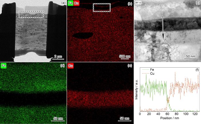
图5
热处理-冷轧Cu-10Fe样品的TEM表征
Fig.5
TEM characterizations of Cu-10Fe sample after HTCR
(a, b) TEM specimen prepared by FIB (a) and the corresponding EDS mapping of the square region in Fig.5a (b) (c-e) TEM bright-field image of the square region in Fig.5b (c) and the corresponding EDS mappings of Fe (d) and Cu (e) (f) EDS line scanning of Cu matrix and Fe fibers phase interface along the arrow in Fig.5c
图6
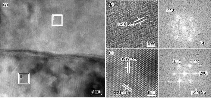
图6
Cu基体与Fe纤维相界面区域的HRTEM表征
Fig.6
HRTEM characterizations of the interface region between the Cu matrix and Fe fibers
(a) HRTEM image of interface region (b, c) HRTEM images and the corresponding fast Fourier transform (FFT) of regions I (b) and II (c) in Fig.6a
2.3 电导率
图7为CS、HT和HTCR态Cu-10Fe样品的电导率。可以看出,冷喷涂Cu-10Fe沉积体的电导率最低,为41%IACS。热处理后样品的电导率最高,为83%IACS。热处理-冷轧后样品的电导率略低于热处理样品,为72%IACS。
图7
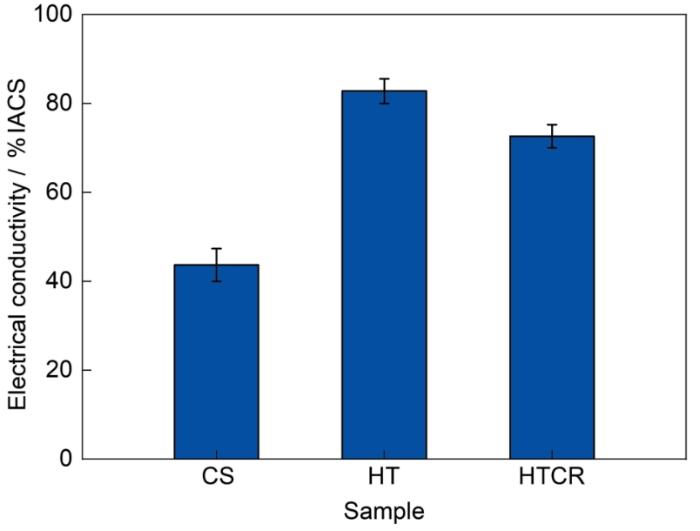
图7
冷喷涂、热处理和热处理-冷轧Cu-10Fe样品的电导率
Fig.7
Electrical conductivities of Cu-10Fe samples after CS, HT, and HTCR
2.4 力学性能
图8a为CS、HT和HTCR态Cu-10Fe样品的工程应力-应变曲线,图8b为相应的屈服强度、抗拉强度和延伸率。冷喷涂沉积体的应力-应变曲线在断裂前没有明显的屈服阶段,表明CS态样品缺乏加工硬化能力,而且由于界面结合不良容易造成样品提前断裂。在HT态和HTCR态样品的应力-应变曲线中,可以观察到屈服后存在明显的加工硬化。高的加工硬化能力对于良好的均匀延伸率至关重要,因为其有助于延迟拉应力下的局部变形(颈缩)[41],因此,HT态和HTCR态样品展现出比CS态样品更优异的力学性能。冷喷涂沉积体的抗拉强度为190 MPa,热处理后样品的抗拉强度提升到233 MPa,延伸率提升到22.0%,热处理可以消除冷喷涂造成的部分残余应力,并促进Cu-Fe沉积体发生回复和再结晶,同时生成退火孪晶(如图4b1所示),这应该是引起力学性能变化的主要原因。冷轧后,抗拉强度进一步提升到550 MPa,屈服强度提升至495 MPa,而延伸率降低到1.9%。首先,冷轧有效降低了Cu-10Fe沉积体的孔隙率,从而增加了材料的有效横截面积,提升了断裂抗力;第二,冷轧过程中产生了大量位错和晶界,如图4c3和c4所示,增加了滑移面进一步滑动的阻力;第三,冷轧过程中非均质Cu/Fe界面发生不协调塑性变形,可以导致界面区域几何必需位错(GNDs)的积累和应变梯度的出现,从而引入异质变形诱导应变硬化[42]。
图8
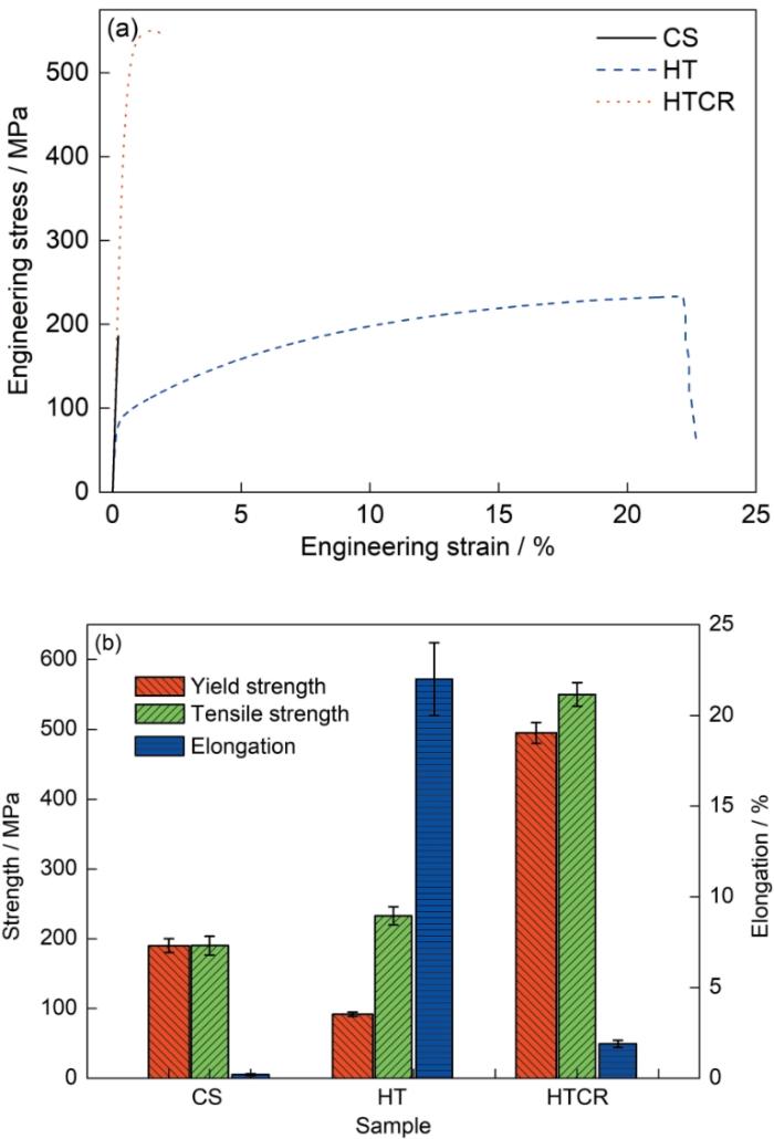
图8
冷喷涂、热处理和热处理-冷轧Cu-10Fe样品的工程应力-应变曲线和力学性能
Fig.8
Engineering stress-strain curves of Cu-10Fe samples after CR, HT, and HTCR (a); and corresponding mechanical properties (b)
图9为CS、HT和HTCR态Cu-10Fe样品拉伸断口的SEM像。CS态样品的断裂面平滑,如图9a所示,表现为脆性断裂。从放大像(图9b)可以看出,Cu沉积颗粒断面由大面积的解理面和台阶组成,Fe沉积颗粒表面很平滑。非键合断裂是喷涂涂层中发生断裂的一个重要微观结构特征,裂纹沿沉积颗粒的界面扩展,而不是通过沉积颗粒,进一步证明冷喷涂Cu-10Fe沉积体发生了脆性断裂。从HT态样品的断裂面形貌可以看出,Cu沉积颗粒中存在大量韧窝,Fe沉积颗粒中观察到解理台阶,如图9c和d所示。这些特征表明,HT态样品的失效机制是韧性和脆性断裂混合机制。从HTCR态样品的断裂面形貌可以看出,Fe纤维表面较为平整,但Fe纤维所占比例较低,Cu基体中仍存在大量韧窝,如图9e和f所示。这些特征表明,HTCR态样品的失效机制主要是韧性断裂。此外,观察HTCR态样品的宏观断口可以发现,断裂面相对作用力方向呈现剪切断裂,进一步证明其为韧性断裂。
图9
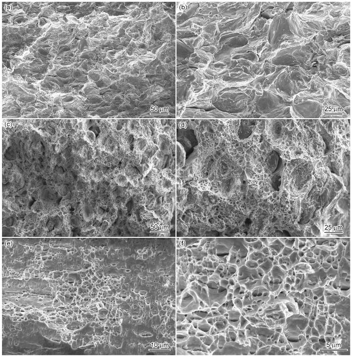
图9
冷喷涂、热处理和热处理-冷轧Cu-10Fe样品拉伸断口形貌的SEM像
Fig.9
Low (a, c, e) and high (b, d, f) magnified SEM images showing the tensile fracture surfaces of Cu-10Fe samples after CS (a, b), HT (c, d), and HTCR (e, f)
3 分析与讨论
3.1 微观结构的演化机制
CS态Cu-10Fe沉积体呈现典型的梯度纳米晶结构特征:超细纳米Cu晶粒(80~800 nm)环绕着微米级变形Fe晶粒(3.5~10.0 μm)以及部分较粗大的微米级Cu晶粒(1.5~10.0 μm),其孔隙率低至0.13%。这种结构的形成是本工作中“原位”复合材料概念的核心体现:增强相(Fe颗粒/纤维)并非预先制备好再混合,而是作为原始粉末组分(图1)在冷喷涂高速撞击基体或已沉积层的瞬间,经历剧烈的塑性变形(图2)从而“原位”嵌入Cu基体之中。在此过程中,Fe颗粒的原始形貌发生显著改变(图2a和4a1),但并未发生熔融或与Cu基体发生显著的相互固溶,保持了其作为增强相的本质特征。同时,颗粒界面区域因极高的应变速率和剪切变形(图4a3)而发生动态再结晶形成超细纳米Cu晶粒,构成了独特的梯度结构。
随后的热处理过程触发了静态回复与再结晶。Cu沉积颗粒内的微米级变形晶粒和纳米晶粒均转变为等轴晶(平均尺寸约3.9 μm),并伴随大量退火孪晶的生成(图4b1和b4)。Fe沉积颗粒也经历了静态回复/再结晶过程,位错密度显著降低(图4b3)。然而,与预期不同[43,44],热处理后沉积体的孔隙率反而增加至0.86%,且部分Cu/Fe界面结合出现弱化现象(图2b和3)。这种界面弱化现象主要归因于Cu与Fe之间显著的热膨胀系数差异(Cu:16.7 × 10-6 ℃-1,Fe:11.7 × 10⁻⁶ ℃-1)。在加热和冷却过程中,Cu基体与Fe颗粒之间由于膨胀/收缩程度不同,在界面区域产生了显著的残余热应力。当此应力超过界面结合强度时,便可能导致界面微裂纹或脱黏的产生,从而增加表观孔隙率并削弱界面结合。
关键的界面修复和致密化发生在后续的大变形量冷轧过程中。在强大的压应力作用下,HT态样品中的孔隙被有效压合,因热失配造成的弱化界面被“锻焊”愈合(图2c)。等轴晶粒沿轧制方向被显著拉长,Cu基体形成强<111>和<211>纤维织构,Fe颗粒则被拉长成具有主导<110>织构的纤维形态(图4c1)。微观结构演化结果表明,冷轧变形是不协调的:较软的Cu基体优先发生塑性流动,在硬质Fe纤维周围产生严重的剪切摩擦变形,导致Fe纤维附近的Cu基体发生动态再结晶和晶粒细化(形成纳米Cu晶粒),而远离Fe纤维的Cu基体则形成细长的层状结构(图4c4)。TEM/EDS分析(图5和6)进一步揭示了HTCR态界面结构的本质:Cu基体与Fe纤维整体上未发生相互固溶,仅在界面区域形成了厚度约20 nm的原子扩散层。该扩散层源于冷喷涂高速撞击时产生的瞬时高温、高压以及大量空位和缺陷[40],以及后续热处理和冷轧过程中界面原子扩散的协同作用。HRTEM分析(图6)证实该扩散层与两侧的Cu基体和Fe纤维晶格紧密连接,形成了冶金结合。因此,HTCR过程最终导致“原位”形成了成分均匀无偏析(区别于铸造)、结构致密、界面结合良好的Cu-10Fe复合材料,其中增强相Fe纤维是由原始Fe颗粒经变形直接转化而来,并与Cu基体形成了具有特定扩散层的冶金结合界面。
这种独特的“原位”形成机制和界面演化过程是材料获得优异性能的关键:首先,固态的冷喷涂沉积及相对较低的热处理温度(600 ℃)有效抑制了Fe原子在Cu基体中的大量固溶(图5b和c),避免了固溶Fe原子对电子的强烈散射[22~24],这是获得高电导率(72%IACS,图7)的根本前提;同时,冷轧的强大压合作用修复了冷喷涂初始缺陷和热处理热失配造成的界面损伤,大幅降低孔隙率(约0.09%,图2c和3),显著提升了材料的有效承载面积和界面结合强度(图2c),使材料强度提升;此外,界面处形成的约20 nm厚的原子扩散层(图5f和6)提供了良好的冶金结合,有利于载荷从基体向增强相的传递;最终,轧制形成的沿轴向高度排列的细长Cu晶粒和Fe纤维结构(图4c1),显著减少了垂直于电流方向的界面和晶界数量[45,46],优化了电子传输路径以利于轴向导电性,同时Fe纤维本身提供了显著的载荷传递强化作用,共同实现了强度与导电性的协同优化。
3.2 力学性能
本工作中,冷喷涂沉积体经过热处理-冷轧后获得了较高的致密度(99.91%),并具有优异的综合性能。热处理-冷轧后样品的主要强化机制是细晶强化、位错强化以及Fe纤维的载荷传递强化。根据混合法则,热处理-冷轧后样品的屈服强度(σROM)可表述如下[47]:
式中,σCu和σFe分别为Cu基体和Fe纤维贡献的强度;φCu和φFe为相应的体积分数,分别为0.93和0.07。
式中,σ0为固有临界分切应力,对于纯Cu而言,约为26 MPa;ΔσGB和Δσdisl分别代表细晶强化和位错强化对Cu基体强度的贡献。
ΔσGB可以根据Hall-Petch关系进行计算[52]:
式中,KP-H为Hall-Petch系数,对于纯Cu而言,约为0.14 MPa⋅m1/2;D为平均晶粒尺寸,根据图4的EBSD数据计算可知D约为0.45 μm。计算得到ΔσGB为209 MPa。
在轧制过程中,Cu基体中形成大量位错,这些位错相互缠结从而阻碍了自身运动,起到强化作用,一般来说,Δσdisl可以用Bailey-Hirsch公式计算[53]:
因此,经过热处理-冷轧后Cu基体的强度约为349 MPa。
Fe纤维主要通过载荷传递机制提供强化。研究[27]表明,基于位错和晶界强化的Fe纤维的屈服强度可以综合计算为:
根据上述的强化机制和混合法则,最终计算出经过热处理-冷轧后Cu-10Fe原位复合材料的屈服强度为367 MPa。计算得到的屈服强度小于测量值(495 MPa)。这种差异可能源于以下原因。
(1) 低估的细晶强化贡献。本工作中,由于EBSD技术的分辨率限制,无法准确表征出尺寸小于80 nm的Cu晶粒结构(特别是Fe纤维附近因动态再结晶形成的超细纳米Cu晶粒区域)。这导致基于EBSD数据计算的平均Cu晶粒尺寸(D ≈ 0.45 μm)有可能显著高于实际值。根据Hall-Petch关系,晶粒尺寸的高估必然造成细晶强化贡献的系统性低估。
(2) 未考虑异质变形诱导(HDI)强化。在冷轧变形过程中,软质Cu基体与硬质Fe纤维之间显著的塑性变形能力差异导致了非协调塑性变形(图4c)。这种非协调变形在Cu/Fe异质界面区域产生了显著的应变梯度。为了容纳这些应变梯度,在界面附近会产生大量GNDs并积累(图4c3)。GNDs的积累会产生长程背应力,阻碍后续位错运动,从而提供额外的强化,这种强化一般被称为HDI强化[42,50,59]。重要的是,这种HDI强化效应不仅存在于制备过程(如冷轧),在后续的拉伸变形过程中仍会持续作用,从而显著提升材料的屈服强度[50]。然而,上述基于材料均质变形假设的传统计算模型(式(
3.3 电导率
根据Matthiessen规则[60],电阻率(Ω)可以用以下关系来表示:
式中,ΩT为纯Cu的电阻率,与温度有关;ΩS、ΩGB、ΩD和ΩP分别为固溶、晶界、位错和析出相导致的电阻率增加。研究[61]表明,微观缺陷的尺度越小,缺陷密度越大,缺陷对电子的散射作用越明显,金属材料电阻率的增加越明显。CS态Cu-Fe沉积体的电导率最低,为41%IACS,这是由于沉积体中存在界面结合不良和孔隙,且冷喷涂过程中颗粒发生剧烈塑性变形,合金中位错密度很高,尤其是颗粒界面区域的超细晶内部的位错密度高、晶格畸变大。热处理后样品的电导率最高,为83%IACS,这主要是由于热处理过程中Cu沉积颗粒和Fe沉积颗粒发生回复和再结晶,位错密度和晶界密度降低;此外,Cu沉积颗粒中生成了退火孪晶,孪晶界对自由电子的散射能力远小于普通晶界[3]。热处理-冷轧后的Cu-Fe沉积体的电导率略低于热处理样品,为72%IACS。冷轧时由于发生剧烈的塑性变形,位错密度和晶界密度均提高,然而,沿轴向伸长的Cu晶粒和Fe纤维有助于提高沿轴向的导电性;此外,轧制过程中喷涂颗粒间界面进一步愈合,孔隙率大幅下降,有利于其电导率的提升。综合作用下,热处理-冷轧后Cu-Fe沉积体的电导率相较于热处理条件下有所下降,但仍远高于其在沉积条件下的电导率。
图10
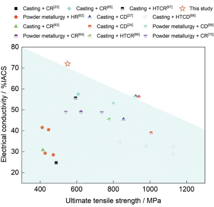
图10
不同方法制备的Cu-10Fe合金的电导率与极限拉伸强度的关系
Fig.10
Relations of electrical conductivity and ultimate tensile strength of the Cu-10Fe alloys with different processes (CR—cold rolling, HR—hot rolling, CD—cold drawing, HTCD—heat treatment and cold drawing)
4 结论
(1) CS态Cu-10Fe沉积体呈现梯度纳米晶结构(超细纳米Cu晶粒环绕微米级变形Fe及Cu晶粒),孔隙率低(0.13%)。热处理诱发静态回复与再结晶,使变形晶粒等轴化、纳米晶长大并生成退火孪晶,显著降低位错密度,但热膨胀失配导致孔隙率增加(0.86%)并弱化部分Cu/Fe界面。热处理-冷轧使晶粒沿轧向拉长,形成具有特定纤维织构的细长Cu晶粒和Fe纤维,并在相界面形成紧密结合的纳米级原子扩散层。该过程显著改善界面结合并基本消除孔隙(孔隙率0.09%),最终获得成分均匀无偏析、结构致密的Cu-10Fe原位复合材料,其抗拉强度约为550 MPa,电导率约为72%IACS。
(2) HTCR态Cu-10Fe原位复合材料的高强度主要源于细晶强化、位错强化以及Fe纤维的载荷传递强化。基于微观结构参数(晶粒尺寸、位错密度)的定量计算得到的屈服强度(367 MPa)低于实测值(495 MPa)。这种差异主要归因于:EBSD分辨率的限制可能导致测量的Cu平均晶粒尺寸偏大,低估了细晶强化的实际贡献;计算中未考虑软Cu基体与硬Fe纤维之间非协调塑性变形导致的显著HDI强化效应。
(3) HTCR态Cu-10Fe原位复合材料的高电导率主要源于:冷喷涂固态沉积有效避免了Cu沉积颗粒与Fe沉积颗粒的相互固溶;热处理-冷轧过程愈合了界面并消除了孔隙;以及拉长的Cu晶粒与Fe纤维沿电流方向排列,减少了电子散射界面。
(4) 与传统方法(如铸造、粉末冶金)制备的Cu-Fe合金相比,本工作采用冷喷涂结合后续热-机械处理工艺制备的Cu-10Fe原位复合材料展现出更优异的强度-电导率协同效应。
参考文献
Refinement effect of C addition on the Cr phase in the as-cast Cu-Cr alloys
[J].
A review on copper alloys with high strength and high electrical conductivity
[J].
Towards sustainable copper matrix composites: Manufacturing routes with structural, mechanical, electrical and corrosion behaviour
[J].
In the last few decades, man has become more innovative in discovering new materials to make his life more sustainable. Copper metal matrix composite is the most promising material for many engineering applications where the higher temperature resistance and good microstructural stability is required. The sustainable development of copper metal matrix composite is based on the use of ceramics as reinforcements. The choice of reinforcement material is highly influenced by their mechanical properties such as hardness, wear resistance, cost advantage, availability in market and refractory nature. In the current scenario, copper and its alloy are gaining popularity due to their high sustainability, high conductivity and good corrosion resistance. However, the relatively low wear resistance and high temperature strength restrict the use of copper in many applications. Recent developments in metal matrix composites have provided new means to produce high sustainable copper metal matrix composite materials with high wear resistance and high strength materials. It has been found that the wear resistance and strength of materials can be improved by adding hard ceramic particles such as Al 2 O 3, SiC, TiC and ZrO 2 into the metal matrix. The aim of the present study is to summarise the research work carried out in the field of sustainable copper metal matrix composites. It also reports the various manufacturing routes along with the structural, mechanical, electrical and corrosion properties. It is found that copper metal matrix composites are preferred over the conventional composites. Sustainability issues around the globe has forced the industries to adopt the eco-friendly materials with their fabrication and machining routes, which results in less carbon emission and also has less affect to the environment. Fabrication of eco-friendly composites is an emerging research area, which has made several research scopes in production of sustainable composites. It is expected that this study can be beneficial for the researcher to decide their research direction in the field of sustainable material production.\n
Study of microstructure evolution and properties of Cu-Fe microcomposites produced by a pre-alloyed powder method
[J].
Strength and conductivity of in situ Cu-Fe alloys
[J].
Strain-induced balancing of strength and electrical conductivity in Cu-20 wt% Fe alloy wires: Effect of drawing strain
[J].
Tailoring the microstructure and mechanical properties of Cu-Fe alloy by varying the rolling path and rolling temperature
[J].
Mitigating adverse effects of Cu-containing intrauterine devices using a highly biocompatible Cu-5Fe alloy
[J].
Comparative study of the influence of Ag on the microstructure and mechanical properties of Cu-10Fe in situ composites
[J].
Synergistic improvement of mechanical properties and electrical conductivity of Cu-Fe alloys by rare earth metals Sc and Y addition
[J].
Effect of Nb content on mechanical reinforcement of the Cu-10Fe composites
[J].
Ultrahigh-strength Cu-10Fe-0.2 Mg in situ composites via ultra-nano precipitation within nanolamellar architectures
[J].
High pressure torsioning of Cu-9Fe-1.2X (X = Co, Ni, Ag) microcomposites and their microstructural and mechanical evolution
[J].
Liquid immiscibility in copper-iron and copper-cobalt systems in the supercooled state
[J].
Research progress on strengthening mechanism of copper-iron alloys with high iron concentration
[J].
高铁含量铜铁合金强化机理的研究进展
[J].
Controlling macroscopic segregation of the directed energy deposited Cu-Fe alloy by laser oscillation
[J].
Microstructure and properties evolution of rolled powder metallurgy Cu-30Fe alloy
[J].
Influence of minor Mg/Ca/Nb/Ag addition on the morphology and microstructure of Fe-rich phase in powder metallurgy Cu-10Fe alloy
[J].
Microstructure and properties of Cu-50Fe alloy produced by chemical co-precipitation and powder metallurgy
[J].
Distinct electrical and mechanical responses of a Cu-10Fe composite prepared by hot-pressed sintering and post treatment
[J].
Cold spraying—A materials perspective
[J].
Microstructure and properties of Cu-10wt%Fe alloy produced by double melt mixed casting and multi-stage thermomechanical treatment
[J].
Microstructure evolution and deformation behaviour of Cu-10wt%Fe alloy during cold rolling
[J].
Heavily drawn Cu-Fe-Ag and Cu-Fe-Cr microcomposites
[J].
Research status, application and challenges of cold spray additive manufacturing technology
[J].
冷喷涂增材制造技术研究现状及应用与挑战
[J].
Microstructure and mechanical properties of cold spray additive manufactured Cu-Cr-Nb and Fe-Ni-Cr alloys
[J].
Excellent strength and electrical conductivity achieved by optimizing the dual-phase structure in Cu-Fe wires
[J].
Deposition of fully dense Al-based coatings via in-situ micro-forging assisted cold spray for excellent corrosion protection of AZ31B magnesium alloy
[J].
Solid-state additive manufacturing high performance aluminum alloy 6061 enabled by an in-situ micro-forging assisted cold spray
[J].
Dynamic recrystallization in the particle/particle interfacial region of cold-sprayed nickel coating: Electron backscatter diffraction characterization
[J].
Microstructural evolution in adiabatic shear localization in stainless steel
[J].
Microstructural evolution of cold-sprayed Inconel 625 superalloy coatings on low alloy steel substrate
[J].
Microstructure and nanohardness of cold-sprayed coatings: Electron backscattered diffraction and nanoindentation studies
[J].
A new approach to prepare fully dense Cu with high conductivities and anti-corrosion performance by cold spray
[J].
Effect of annealing process on interface microstructure and mechanical property of the Cu/Al corrugated clad sheet
[J].
Multi-scale annealing twins generate superior ductility in an additively manufactured high-strength medium entropy alloy
[J].
Crystallographic orientation on raft-like structure developed by tensile deformation in Cu-Fe dual phase alloy sheet
[J].
Effect of cold working deformation on microstructure and properties of powder metallurgy copper-iron alloys
[J].
冷加工变形量对粉末冶金铜铁合金组织与性能的影响
[J].
The transition from discontinuous to continuous recrystallization in some aluminium alloys: I—The deformed state
[J].
High resolution microstructure characterization of the interface between cold sprayed Al coating and Mg alloy substrate
[J].
Fractal structure and nano-precipitates break comprehensive performance limits of CuCrZr alloys
[J].
Design of pure aluminum laminates with heterostructures for extraordinary strength-ductility synergy
[J].Heterogeneous metals and alloys are a new class of materials with superior mechanical properties. In this paper, we engineered sandwich-structured pure aluminum laminates composed of middle coarse-grained layer and outer fine-grained layer via extrusion, rolling and annealing. By controlling the post-annealing regimes, a larger degree of microstructure heterogeneities such as boundary spacing, misorientation and texture across the hetero-interface were obtained, which resulted in obvious mechanical differences. Tensile tests indicated that the 300 °C/30 min annealed laminates enabled a relatively high tensile ductility while simultaneously retaining a high strength, which was better than prediction by the rule-of-mixture. To explain the reasons behind it, the evolution of geometrically necessary dislocations and strain gradient at the hetero-interface zone were detected using in-situ tension and microscopic digital image correlation technique. It was found that with the increasing applied strain, a significant strain gradient was developed near the interface, which was accommodated by geometrically necessary dislocations, thereby contributing to higher hetero-deformation induced (HDI) strengthening and hardening.
Research progress of cold spray in Institute of Metal Research, Chinese Academy of Sciences
[J].Owing to low spraying temperature and high particle velocity, cold spray is a rapidly developing solid-material deposition technology that has broad application prospects in areas of metal coating preparation, additive manufacturing, and component repair. The Institute of Metal Research, Chinese Academy of Sciences, has conducted extensive research on cold spray, including the exploration of bonding mechanism, strategies and methods of tailoring microstructures and properties of deposits, and application of the cold spray technology. This paper systematically introduces the research progress of cold spray by the Institute of Metal Research, Chinese Academy of Sciences.
中国科学院金属研究所冷喷涂技术研究进展
[J].冷喷涂具有喷涂温度低和颗粒速度高的特点,是一种发展十分迅速的材料固态沉积技术,在金属涂层制备、增材制造和零部件修复方面具有广阔的应用前景。作为国内最早从事冷喷涂技术研究的单位之一,作者所在单位中国科学院金属研究所在冷喷涂沉积层的结合机制探索、组织性能调控及技术开发应用等方面开展了大量的研究工作。本文将围绕上述方面系统介绍中国科学院金属研究所冷喷涂技术的研究进展。
Towards high-strength cold spray additive manufactured metals: Methods, mechanisms, and properties
[J].Cold spray, as a solid-state additive manufacturing process, has been attracting increasing attention from both scientific and industrial communities. However, cold-sprayed deposits generally have unfavorable mechanical properties in their as-fabricated state compared to conventionally manufactured and fusion-based additive-manufactured counterparts due to the inherent microstructural defects in the deposits (e.g., porosity and incomplete interparticle bonding). This downside reduces its competitiveness and limits its wide applications as an additive manufacturing process. In the past years, many strengthening technologies have been developed or introduced to adjust the microstructure and improve the mechanical properties of cold-sprayed deposits. The term “strengthening” in this work specifically refers to improving the mechanical strength, particularly the tensile strength of the cold-sprayed bulk deposits. According to the stage that the strengthening technologies are used in the cold spray process, they can be classified into three categories: pre-process (e.g., powder heat treatment), in-process (e.g., powder heating, in-situ micro-forging, laser-assisted cold spray), and post-process (e.g., post heat treatment, hot isostatic pressing, hot rolling, friction stir processing). Therefore, a comprehensive review of these strengthening technologies is conducted to illuminate the possible correlations between the strengthening mechanisms and the resultant deposit microstructures and mechanical properties. This review paper aims to help researchers and engineers well understand the different strengthening methods and provide guidance for the cold spray community to develop new strengthening strategies for future high-quality mass production.
Enhanced electrical conductivity and mechanical properties in thermally stable fine-grained copper wire
[J].
Enhancing strength and electrical conductivity of Cu-Cr composite wire by two-stage rotary swaging and aging treatments
[J].
Microstructure and strength of Cu Fe in situ composites after very high drawing strains
[J].
Evolution of microstructure and mechanical properties in Cu-14%Fe alloy during severe cold rolling
[J].
Superior strength-ductility combination resulted from hetero-zone boundary affected region in Cu-Fe layered material
[J].The hetero-zone boundary affected region (HBAR) significantly influences the mechanical behaviors of layered materials, where the deformation mechanisms differ from those in the bulk layers. In this study, three kinds of heterogeneous Cu-Fe layered materials with different interface spacing but identical total thicknesses were prepared. The effects of HBAR and strain partitioning on the tensile behavior of the layered materials were investigated. The results showed that layered materials had enhanced yield strength and uniform elongation with decreasing interface spacing. During tensile deformation, geometrically necessary dislocations (GNDs) were generated at hetero-zone boundaries and piled up near them, resulting in hetero-deformation induced (HDI) strengthening and HDI work hardening. Surface profilometry measurements showed that the Cu and Fe layers exhibited obvious strain partitioning and mutual constraint. With decreasing interface spacing, strain partitioning is enhanced by interlayer constraint, which prevented strain localization at interfaces and thus improved the synergetic deformation of layers. A higher fraction of HBAR can improve the mechanical performance of heterogeneous layered materials. This study deepens our understanding of the relationship between HBAR and strength-ductility synergy and provides some insight into the design of layered materials.
Microstructural stability and mechanical response of Cu-Ag microcomposite wires
[J].
Strengthening mechanisms in a high-strength bulk nanostructured Cu-Zn-Al alloy processed via cryomilling and spark plasma sintering
[J].
A precipitation-hardened high-entropy alloy with outstanding tensile properties
[J].
Size effect on the tensile strength of fine-grained copper
[J].
The effect of dislocation contrast on X-ray line broadening: A new approach to line profile analysis
[J].The x-ray line profiles of an ultrafine grained copper crystal, produced by equal-channel angular pressing, were measured by a special high resolution diffractometer with negligible instrumental line broadening. The analysis of the line breadths and the Fourier coefficients have shown that taking into account the contrast caused by dislocations on line profiles gives new scaling factors in the Williamson–Hall plot and in the Warren–Averbach analysis, respectively. When strain is caused by dislocations the new procedure proposed here enables a straightforward determination of particle size and strain, the latter in terms of the dislocation density.
A method to calculate the dislocation density of a TWIP steel based on neutron diffraction and synchrotron X-ray diffraction
[J].The modified Williamson-Hall method, which has been widely used to calculate dislocation densities of high-strength steels and other structural alloys, is re-examined in this work, and is further applied to calculate the dislocation density of a deformed twinning-induced plasticity (TWIP) steel by using its neutron diffraction patterns and synchrotron X-ray diffraction patterns. This paper aims not only to promote the proper use of the method but also to shed light on its underlying pre-requisites and assumptions, and is thus expected to help avoid any errors during its usage.
基于中子衍射和同步辐射X射线衍射的TWIP钢位错密度计算方法
[J].本文详细梳理并介绍了被广泛应用于高强钢及其它结构金属材料位错密度计算的修正Williamson-Hall法,并结合中子衍射和同步辐射X射线衍射实验结果,以一种孪生诱发塑性(TWIP)钢为例,计算其在变形后的位错密度演化。本文详细介绍如何正确使用该方法以及如何避免常见的一些错误,并介绍其背后的原理及假设。
Quantifying dislocation density in Al-Cu coatings produced by cold spray deposition
[J].
Investigation on the dual-phase co-deformation behavior and strengthening mechanism in cold-drawn Cu-20Fe alloy
[J].
The role of layer strength ratio in enhancing strain hardening and achieving strength-ductility synergy in heterostructured materials
[J].
Modeling the electrical resistivity of deformation processed metal-metal composites
[J].
Research progress on effect of length scale on electrical resistivity of metals
[J].With the development of micro/nano-technologies, microstructural scales or geometrical dimensions of metal conductors in the micro/nano-devices are becoming shrunk from macroscopic scale to micron scale, submicron scale and even nanometer scale, leading to the fact that the electrical resistivity of metal conductors at room temperature tends to exhibit evident size effects. Recent studies on the electrical resistivity of metal conductors at different length scales were reviewed in this paper, focusing on the effects of the geometrical scales of microscalematerials and of the scale of microstructures and defects in the materials as well as the relevant theoretical models. Finally the developing tendency of the investigations on the electrical resistivity of metal conductors and the service reliability of the microscale metals in the future are also addressed.
尺度对金属材料电阻率影响的研究进展
[J].随着微/纳米技术的发展, 在微/纳尺度器件中金属材料的几何尺度或微观结构尺度从宏观尺度逐渐减小到微米、亚微米甚至纳米量级, 其室温电阻率往往表现出明显的尺寸效应。本文总结了近年来关于不同尺度金属材料电阻率的研究进展, 重点介绍了金属材料的微观结构、缺陷尺度以及几何尺度对金属材料电阻率的影响及相关的理论模型, 探讨了材料内部微观结构尺度与几何尺度对材料导电性能的影响规律。最后, 对微尺度金属材料电阻率及其服役可靠性的研究趋势进行了展望。
Effects of Fe content on microstructure and properties of Cu-Fe alloy
[J].
Grain refinement and mechanical properties enhancement of Cu-10wt%Fe alloys via Zr addition
[J].
Microstructure and properties of Cu-Fe alloys fabricated via powder metallurgy and rolling
[J].
Effect of cryogenic rolling and intermediate aging on mechanical reinforcement of the Cu-Fe-Nb composites
[J].
Influence of deformation processing on mechanical and conductivity properties of Cu-Fe composites
[J].
Cu-Fe复合材料的形变对其力学性能及导电性能的影响
[J].
Effects of Si addition on mechanical, electrical and magnetic property of Cu-10Fe alloy
[J].
Deformation processing and strength/conductivity properties of Cu-Fe-Ag microcomposites
[J].


