


自1895年Röntgen发现X射线以来,X射线成像领域一直在稳步发展。由于X射线的波长比可见光短得多,利用其成像可以达到的理论分辨率比可见光高几个量级[1]。而且,X射线具有很强的穿透性,可以对厚样品内部结构进行无损成像,使得X射线无损检测技术在材料科学领域具有广泛的应用[2]。近年来利用X射线对物质进行探测方面,已在相衬成像、能谱成像、荧光成像、散射成像、衍射成像、空间关联成像、运动衬度成像等方法及其与显微电子计算机断层扫描(computed tomography,CT)的结合上取得了长足的进步与发展[3~9]。一方面,X射线成像探测利用物质与X射线作用的不同性质,表征物质的不同特征,如吸收特性、相位特征、散射特征、运动特征[10]等,从而区别不同物质进行成像观测。另一方面,不同的X射线成像方法均不约而同地从二维投影成像走向了三维空间分辨成像,三维分辨成为了物质表征不可或缺的一个环节和技术发展的不懈追求。X射线显微CT成像是一种通用的成像技术,通过将X射线束应用到样品上,收集一个用于三维重建的投影数据集[11]或与其他成像方法[12]相结合的旋转数据集,便可生成完整的三维重建图像,并对内部结构缺陷和组成成分进行无损分析,例如空洞、分层,甚至内部的裂纹、元素种类等[13,14]。然而,一个完整的X射线CT成像首先是由X射线源连续产生X射线束,穿过载物台上的样品,样品由载物台及控制系统进行精确地定位和旋转。未被样品吸收的X射线被探测器收集,得到样品某一角度的二维图像。然后旋转样品,对其进行180°或360°投影,以获得各个角度的二维投影,再将这些二维投影通过一定的图像重建算法对样品进行三维再现。显然该方法耗时费力,即使目前已经发展出了利用压缩感知算法对欠采样数据进行迭代重建的技术[15]以及有限角度CT重建技术[16],该方法仍对样品原位装置和时间分辨有着严苛的要求。
目前,国内已完成建设的上海同步辐射装置(Shanghai Synchrotron Radiation Facility,SSRF)是一台第三代中能同步辐射装置,也是我国最大的大科学装置之一。其中,X射线成像及生物医学应用光束线站13HB (原13W线站)基于X射线显微成像功能已在生物医学、材料科学等领域取得了广泛应用和显著成果[3],上述三维成像方法也基本建立完成。但是,一些带有原位加压加温条件的装置,因物理结构、尺寸、质量等因素的限制,无法采集完备的投影数据用以三维CT重建[17]。另一些对于时间分辨能力有较高要求的实验,如金属的熔融与凝固、枝晶生长实时成像等实验,因缺少能与快速动态CT转台相结合的原位装置,尚无较为有效的三维X射线显微成像方法,目前多以二维投影成像为主[18]。特别是一些板状样品,其横向尺度远大于厚度,在采集其CT投影数据时,X射线平行于板面和垂直于板面的投影图差异大,导致难以平衡兼顾,也会对CT重建带来较大的负面影响[19]。同时,一些对辐射剂量敏感的样品如生物样品,CT多投影数据的采集会带来较大的辐射损伤,因此,获取样品三维结构的同时降低辐射剂量是此类样品面临的最大挑战[20]。基于此,上述领域的成像表征亟需一种快速、简便可行的三维成像方法。
在金属凝固领域,熔融金属由于其固有的高温和不透明性,传统的表征方法无法捕捉金属凝固过程的动力学特征。同步辐射X射线成像方法的发展为实时观测金属凝固过程提供了强有力的技术支撑[21,22]。1999年,Mathiesen等[23]通过二维成像首次成功实现了对低熔点合金凝固过程中枝晶长大行为的实时观察。随之,学者们利用该技术观察到一系列典型的金属凝固现象,如枝晶解离与断裂、枝晶粗化、柱状晶向等轴晶转变和固/液界面演变等[24~27]。这种现场的实时观测为金属凝固动力学模型提供了最直接的证明,并为凝固模型的改进提供了指导。然而,由于枝晶生长过程是一种三维动态的过程,二维成像技术无法获得足够的枝晶生长的三维形貌信息,尤其是他们的侧枝状态。虽然同步辐射X射线CT成像能够提供大量的多角度三维视场图片,为建立三维枝晶生长形貌提供了可能性,但是这种技术对金属熔化的原位实验装置要求相当高,整个装置通常需要满足大角度的旋转(180°),并且每次投影间隔的旋转精度、旋转速率必须满足枝晶生长过程快速的时间变化要求。然而,枝晶的生长过程并不是静态的,当不同旋转角度的数据被记录时,枝晶结构会发生变化,这会导致重建结果的不准确性。因此,在大部分的工作中,同步辐射X射线CT成像的研究通常局限于金属凝固过程的后期和冷却完成阶段,这是因为在这个阶段已经有了很好的树枝状固/液混合物,能够有足够的时间给予原位装置的旋转并获取投影图片[28]。当然,有研究者们寄期望于降低收集数据集所需的时间用于减少枝晶三维结构重建的误差,目前已经降低到约0.15 s。然而,这种极低的时间分辨率是以牺牲空间分辨率为代价的,并且得到的数据分辨率过于粗略,甚至无法分辨出枝晶的树枝态结构。总之,高温合金熔体凝固的同步辐射成像研究,其复杂的原位装置、快速的时间变化、扁平的熔炉形状均使得CT成像难以实现[29]。因此,仍需要结合同步辐射X射线成像条件,开发新的三维成像技术,平衡时间与空间分辨率的矛盾,建立更有效的三维快速成像表征方法。
针对传统三维重建技术因成像时间长、设备要求高等限制而无法实现快速成像这一问题,本工作基于视差原理和双目立体视觉技术,提出了一种快速获取三维信息的X射线体视成像方法,该方法将体视成像与X射线透视成像相结合,当目标物置于载物台上时,通过旋转载物台获得2个角度的投影图像,根据获得的投影图像基于立体匹配和视差原理实现目标物体不同深度的重建,可以快速实现对目标物的准确三维重建,从而为高温合金熔融与凝固的原位三维成像实验提供实用可行的成像方案。
1 成像方法
1.1 双目投影获取
完整的立体视觉系统主要分为5个部分,分别是图像采集、探测器标定、特征提取、立体匹配和三维重建。双目影像的获取是第一步,决定着后续步骤的实施。本工作的X射线双目投影图像是在X射线CT系统中采集获得的。将成像样品放置在可旋转的样品台上,快速采集2张不同角度的投影图,考虑到原位装置不易转动,2张投影图只需要相差很小的角度便可满足重建的需要[36]。由于是旋转样品台得到的透射投影成像,探测器标定这一步骤可以简化,准平行光使得样品特征位于两幅投影的同一高度上。
1.2 视差获取算法
视差获取算法包含了特征提取和立体匹配这2个紧密联系的内容。立体匹配的目标是从不同视角采集的图像中找到与特征点相匹配的对应点,然后通过空间特征点在两幅图中的位置关系来计算视差,从而通过视差求得空间各点的深度坐标。国内外学者均对图像匹配做了大量研究,根据算法使用图像信息的不同一般分为2类:基于灰度的匹配法和基于特征的匹配法。基于灰度的匹配方法,例如,平均绝对差(mean absolute difference,MAD)算法,该算法是通过灰度值之差的绝对值总和再取平均值的方法计算特征相似度,计算量小且匹配准确率较高,因此在图像匹配中得到了广泛应用。Barnea和Silveman[37]提出了归一化互相关(normalized cross correlation,NCC)算法,利用子图与模板图的灰度,通过归一化的相关性度量公式来计算2者之间的匹配程度,提高了匹配的速度和精度。基于特征的匹配算法则是在被检测样品的采集图像中提取出最明显的特征应用于立体图像匹配。例如,2012年,Wang等[38]提出了双边滤波尺度不变特征变换(bilateral filter scale-invariant feature transform,BFSIFT)算法,使用双边滤波进行尺度空间构建,可以有效地保留图片的边缘信息,提升了图像匹配性能,但是双边滤波、双向匹配导致算法计算速度减慢。2015年,王睿和朱正丹[39]提出使用图像的形状特征和色彩特征来进行图像特征的额外描述,进一步降低了尺度不变特征变换(scale-invariant feature transform,SIFT)算法的误匹配率。由于X射线影像是灰度的,本工作采用基于灰度匹配的MAD算法作为体视成像的匹配算法。在本方法中认为X射线为准平行光,双角度投影下的图像匹配搜索范围不同于可见光的双相机方案,其应是以某特征点为原点由负到正的一段范围。当算法匹配到相同的特征点时,该特征点在两幅双目投影图中的坐标差便为视差,该视差对应着特征点的深度信息。
1.3 深度信息重建
根据视差可以重建特征点的深度信息,不同于双相机立体视觉的深度计算,采用旋转样品台得到的双目投影,其几何关系如图1所示。因入射X射线近似为平行光,特征点在两投影中具有同一垂直坐标,其中绿色点(x1, y1)经旋转θ角度后,转动至红色点(x2, y2)处,坐标Y为待重建的深度信息,空间坐标X是该特征点在探测器上的坐标。两坐标点满足旋转关系,如
图1
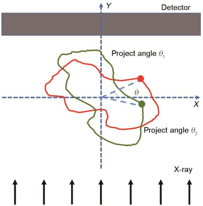
图1
体视成像投影视差与深度关系示意图
Fig.1
Schematic of the relationship between projection parallax and depth in stereo imaging (θ—angle difference of the binocular projection)
式中,(x1, y1)和(x2, y2)是某特征点在双目投影中的空间坐标,此处θ表示为双目投影的角度差。使用MAD算法匹配特征点并计算出投影图中每个像素的视差后,按照上述公式便可重建深度。如此,每一个像素点除了其自身的灰度特征外还有一个三维坐标。在三维显示软件中便可观察该样品的三维特征,并进行后续的测量和计算。
2 实验方法及结果
2.1 已知样品验证
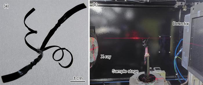
为了验证本方法的可行性和有效性,将一个已知的静态样品放置在实验室X射线CT成像系统中用于X射线体视成像实验。该样品为4个伸向不同方向的螺旋金属丝,金属丝外包裹一层绝缘橡胶,因此在可见光下看起来较为扁平。样品如图2a所示,4个不同方向保证了样品具有较大的深度区间。其中,螺旋形状保证了样品具有不同的深度细节。成像系统由XWT-225-The Plus微焦点透射式钨靶X光管、RA16A-WH01样品台、Rad-icon 2329互补金属氧化物半导体(complementary metal oxide semiconductor,CMOS) X射线平板探测器组成,如图2b所示。探测器像素尺寸为49.5 μm,采用4倍bining模式,即像素尺寸为198 μm,像素阵列1152 × 1472,成像面积228 mm × 291 mm。设置X光管管电压为50 kV,管电流为200 μA,焦点尺寸为2 μm。将样品放置在样品台上,调节合适的成像距离,使探测器能完整地对样品成像。此时,光源点与样品距离为25 cm,样品与探测器距离为25 cm,即2倍的物象放大关系。
图2
设置样品台转速为20°/s,旋转样品台,选取一个合适成像的视角,采集一个投影数据之后转动样品台将样品旋转8°,采集另一张投影数据组合成体视成像的双目投影影像,如图3a所示。使用本工作算法,基于图3a所示双目影像,并以左图为基准,计算样品各像素点视差。为了更加直观地观察立体匹配后的视差关系,将视差按照从大到小的顺序伪彩色处理,如图3b所示。其中,以旋转中心为原点,远离观察者的方向为正方向,视差取值范围为-50~20个像素。视差也间接代表了样品的深度关系,视差为负值的地方(即颜色越偏红色的特征点)离观察者越近,视差为正值的地方(即颜色越偏蓝色的特征点)离观察者越远。根据视差及其与深度的换算关系,图3b中A、B 2点在空间深度上的差异为533个像素,对应的实际深度范围为533/2 × 198 μm = 5.28 cm,符合样品实际空间关系。与此相同,图像中任意一点的深度坐标与任意2点间的深度差值均可通过计算得到。
图3
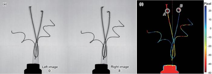
图3
双目投影及其对应视差(A、B 2点深度差为5.28 cm)
Fig.3
Binocular projection (a) and corresponding parallax diagram (b) (The depth difference between the two points A and B is 5.28 cm)
按照本工作方法部分所述,以左图为基准,提取像素灰度值信息和横、纵坐标,并基于深度重建添加相应的深度坐标,将重建好的立体影像保存成三维矩阵形式,并输出为多层切片。将所有切片导入三维渲染软件ImageJ中,获取样品的三维显微结构,进而实现其内部结构的直接观测和分析。本实验中,选取多个视角观察重建后的样品,如图4所示。需要注意的是,对于越是复杂的样品,体视成像越是不能像CT那样查看样品任意角度的三维影像,其观察视角只有在与双目视角保持大致一致时才有最佳的视觉效果,如图4a~c所示。对于偏离体视成像视角太多的观察角度,则三维渲染影像将会发生畸变。但对于结构越简单的样品,其体视成像重建与CT重建结果就越为接近。从图4的三维渲染图和图3b的视差重建图中可以看出,该静态样品大的深度关系被很好重建,螺旋的深度细节部分也被较好恢复,证明了本工作方法的可行性和有效性。
图4
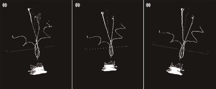
图4
体视成像三维重建——不同角度下的三维渲染效果(偏差-6°、双目视角和偏差6°)
Fig.4
Three-dimensional reconstructions of stereo imaging: 3D rendering effect under different angles
(a) deviation of -6° (b) binocular view (c) deviation of 6°
2.2 高温合金熔体凝固实时原位成像
高温合金熔体凝固的同步辐射X射线实时原位体视成像实验在上海光源快速X射线成像线站(16U2)进行。该线站有着较高的光子通量,可以进行X射线的超快成像实验。同步辐射的高通量X射线使得金属凝固成像实验具有高时空分辨率特性,迅速采集高温合金熔体快速熔化和冷却的二维投影,可分析出不同工艺参数下微观组织演变规律,对高温合金微观组织和工艺关联关系研究具有重要意义[40,41]。然而,复杂的原位加热装置使得动态显微CT成像无法实施,即使样品处在恒温状态、内部结构不变化,也难以对其进行显微CT成像(实验装置如图5所示),这使得研究合金冷却时结晶的微观组织三维动态结构难度较大,在二维投影中,复杂的叠加影像也会干扰分析的准确性。但原位装置在有限的旋转角度内并未完全阻挡射线的透过,其视场中仅有金属熔融样品,这给原位体视成像实验的实施提供了方便。
图5
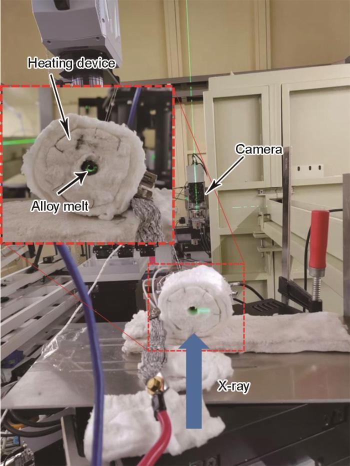
图5
镍基高温合金熔体凝固成像实验装置
Fig.5
Experimental device for melt solidification imaging of nickel-based superalloy
实验使用ORCA-Flash 4.0 C11440高分辨相机搭配光学转换系统(Optique Peter,single objective monochromatic microscope)采集X射线影像数据,相机基础像素尺寸为6.5 μm,共有放大倍数为2、4和10倍的3种可选光学镜头,像素阵列为2048 × 2048。原位加热装置和样品放置在Rotary Stage RT250S气浮转台上,转台最大转速为120 r/min。图6是镍基高温合金熔化-凝固过程中实时二维快速成像结果。通过二维投影图可以看出,随着保温时间的增加,高温合金逐渐开始熔化,然后在降温过程中逐渐凝固。保温时间在3.98~17.40 s时,样品表面出现多次灰度跟裂纹状起伏,这可能说明合金内部已经开始熔化,可是由于表面金属膜的阻挡,在二维投影中无法看到样品内部的熔化情况。29.92 s后,高温合金表面膜逐渐开始分解,露出内部的熔融金属液。随之,高温合金表面逐渐分解成岛状结构,岛与岛之间存在金属液的流动。岛状结构随时间缓慢消解,最后金属表面形成颗粒状的形貌。在随后的降温过程中,孤岛状熔滴经过降温冷却而凝固,衬度缓慢加深。可以看出,在二维成像过程中,只能观察到样品表面的某些信息,无法在深度层面上得到三维信息。
图6
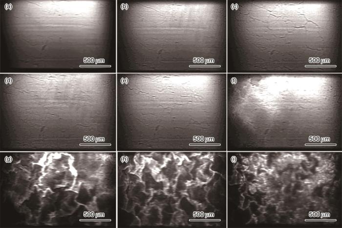
图6
镍基高温合金在高温炉内连续升温和冷却过程中随时间的形态演变
Fig.6
Morphological evolutions of nickel-based superalloys over time during continuous heating and cooling in a high temperature furnace
(a) 0 s (b) 3.98 s (c) 5.52 s (d) 15.65 s (e) 17.40 s
(f) 29.92 s (g) 46.45 s (h) 165.34 s (i) 338.35 s
在双目体视成像时,保持熔炉温度稳定,通过更换样品台角度,迅速获得样品在准静态条件下的双目投影,双目视角相差4°,转台转动完成时间约为100 ms,小于单帧影像曝光时间300 ms。扁平状的熔炉及熔炉内的高温合金凝固样品垂直于入射光放置。立体重建的效果如图7所示(视频文件见视频1),重建方式与图4相同。图7a为样品整体的形貌重建,图7b和c为不同视角下的局部放大图。为了更加直观地显示高温合金凝固样品的深度信息,其等高线图被绘制出来,如图7d所示。深度信息的重建增加了合金凝固的形态测量维度,使该实验的数据分析更为全面和准确。由图可知高温合金熔体凝固后形成的孤岛状组织在大视场下的相对空间位置,例如图7d中红圈内黄色孤岛相对于绿色区域大约高出70个像素尺寸,每个像素3.25 μm,该高度约为0.23 mm。同样计算可得黄色孤岛相对于蓝色区域高出约1.04 mm。然而这些深度上的信息在图7e所示的二维投影图中无法得到。由于深度信息得到重建,可以解析出各孤岛在厚度方向上的位置分布,为后续测量凝固形貌的三维空间分布提供了有力支撑。
图7
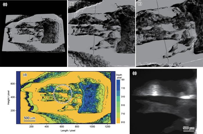
图7
高温合金熔体凝固组织形貌深度信息的体视成像重建
Fig.7
Stereo imaging reconstruction of depth information of melt solidification microstructure of superalloy
(a) integral topography rendering
(b) locally enlarged image
(c) locally enlarged image from another perspective
(d) contour plot of depth
(e) 2D projection
3 分析与讨论
3.1 同步辐射X射线不同成像方法对比
表1 同步辐射X射线成像方法对比
Table 1
| Method | Spatial resolution | Temporal resolution | Imaging information | Device requirement |
|---|---|---|---|---|
| Projection imaging | Submicron | 1 ms | 2D | Low |
| CT | Submicron | 5-30 min | 3D | High |
| Stereo imaging | Micron | 1 s | Stereo | Moderate |
3.2 体视成像方法及其应用的特点
此前,王飞翔等[36]在上海光源13W线站建立了一套基于毛细管分光装置的X射线体视成像系统和方法,与本工作方法不同的是,毛细管装置分出的光束严重依赖毛细管质量,这会导致光源品质的降低,致使两束光场有不同程度的扭曲变形,成像质量难以控制。同时该装置也会带来光子通量的大幅度损失,不利于快速的三维成像。因此本工作针对高温合金凝固成像优化了实验装置,通过旋转样品至某一小的角度,实现双目投影影像的采集。这对于准静态样品或过程可控的动态样品,但CT数据采集受限的体系是可以接受的。在算法方面,先是以静态的人工金属制品为标样验证本工作立体匹配和深度重建算法的正确性。基于旋转投影双目视觉的深度重建(如图1所示),某特征点视差值的正负对应着其深度坐标相对于原点的方向。另外,远离旋转中心的特征点获得的视差更大且更容易被分辨。同时,远离视野中线即Y坐标绝对值越小的特征点视差更小更不容易被分辨。因此,选择合适的体视成像视角将更有利于感兴趣区域的深度方向重建。在双目视角之差即2次透射投影时样品台转动角度的选择上可以遵从如下原则。对于简单样品可以使用略大的角度从而增加成像的视差和重建的精度,这类似于人类视觉在观察近处环境时有更好的深度感知。但是由于X射线投影成像是叠加像,大的角度会导致双目影像差异过大从而匹配失败。因此,对于较为复杂的样品使用略小点的投影角度差。从本工作的静态样品验证实验来看,在体视成像视角下,所重建的三维影像信息更加逼真,接近CT重建,各像素重建的深度值符合真实值,深度细节也得到了还原。基于重建的深度信息,可以对感兴趣点进行三维测量,同时也可以在三维渲染软件中直观观察。但需要注意的是,区别于CT成像技术从大量二维投影数据中重建样品体素,体视成像仅仅是将二维投影的像素赋予三维坐标,因此很难从任意角度视察样品,越是偏离双目视角的方向,三维影像的畸变就越大。而且,越是复杂的样品这种效应也越加明显,也就是说越是简单的样品,其成像效果越接近于CT。但对于本工作的高温合金熔体凝固动态实验来说,体视成像视角的选择就简单得多,扁平的熔炉形状决定了有限的厚度方向是立体重建的目标。熔炉在工作状态为竖直的扁平状,这在CT中是劣势但是在体视成像中却是优势。其冷却结晶在厚度上存在一些类似于沟壑一样的形态分布,结构也相对简单,但在二维投影中很难得出这样的信息和结论。近年来,研究人员已经逐渐意识到材料三维表征的意义,为了更好地优化结构部件的性能和延长使用寿命,跟踪底层三维微结构在加工和使用过程中的演变至关重要。其中,追踪金属凝固过程中的三维形貌演变是典型的应用。通过对三维深度信息的处理,可以获得金属内部熔化和凝固过程微结构的实时演变信息,对理解金属凝固过程动力学机制和凝固后组织形貌均有重要意义。
本工作的算法存在如下缺点:由于X射线透视成像采集的是物体在射线方向上的叠加像,不同角度下的透射图像具有不同的叠加关系,使得双目影像细节差异较大,容易引起图像特征匹配算法的错误造成误匹配,深度信息重建失准。后续或许可以通过投影影像的图像分割和分层处理解决这一问题。但对于结构简单的样品,或者本工作同步辐射体视成像实验中的这类样品,其工作状态下为竖直的薄片形状,该结构反而更适用于体视成像的数据采集而非CT成像。其次,本工作通过旋转样品的方式获取双目投影影像,这降低了体视成像的时间分辨率,对实验的原位装置也有一定要求。在未来,通过引入更为先进的X射线分光装置或采用双源X光系统可实现对样品进行实时的体视成像。
4 结论
基于双目视差的体视成像原理,提出了一种快速获取样品三维信息的同步辐射X射线体视成像方法,将双目立体视觉与X射线透视成像技术相结合,通过旋转载物台获得2个角度的投影图像,根据获得的投影图像经立体匹配,从而获取双目视差实现目标物体不同深度的重建,快速实现对目标物的准确三维重建。利用螺旋金属丝样品,验证了方法的有效性。进而,在高温合金熔体凝固过程应用中,该方法能够给出凝固组织在厚度方向的位向关系。该方法能克服同步辐射光源CT成像的原位装置限制,对于高温金属熔体整体凝固组织的形貌观察能给出大区域的深度信息,可为后续高温合金熔体凝固微观组织的定量化表征提供新的原位成像方法。
文中视频可通过以下网址在线观看:
参考文献
Three-dimensional nano-coherent diffraction imaging technology based on high order harmonic X-ray sources
[J].
基于高次谐波X射线光源的三维纳米相干衍射成像技术
[J].
Variable Zoom technique for X-ray computed tomography
[J].
Methodology development and application of X-ray imaging beamline at SSRF
[J].
Real-time X-ray imaging of mouse cerebral microvessels in vivo using a pixel temporal averaging method
[J].
Calibrating the linearity between grayscale and element content for X-ray KES imaging of alloys
[J].
Megapixel X-ray ghost imaging with a binned detector in the object arm
[J].
Move contrast X-ray imaging of electrochemical reaction process in electrolytic cell
[J].
电解池电化学反应过程的运动衬度X射线成像
[J].
Double-exposure method for speckle-tracking X-ray phase-contrast microtomography
[J].
Efficient three-dimensional characterization of C/C composite reinforced with densely distributed fibers via X-ray phase-contrast microtomography
[J].
Sensitive imaging of intact microvessels in vivo with synchrotron radiation
[J].
Phase-contrast X-ray microtomography links Cretaceous seeds with Gnetales and Bennettitales
[J].
Nondestructive and quantitative characterization of bulk injection-molded polylactide using SAXS microtomography
[J].
Application of high resolution transmission X-ray tomography in material science
[J].
The continuing development of X-ray light sources, optical devices and image analysis technologies enables us to nondestructively analyze internal structures of materials by using 3D imaging with a spatial resolution of micron, even dozens of nanometers. Innovations in materials science and technology will benefit from the new achievements of the X-ray tomography with higher resolution. This article devotes to review the origination and development of the X-ray tomography techniques for 3D imaging and introduce the principles and specifications of three imaging methods, including absorption imaging, phase contrast imaging and holographic imaging. The differences between synchrotron-based and laboratory-based X-ray tomography are also discussed. To explore new opportunities of the high resolution X-ray tomography in the development of material science and technology, particular emphasis is laid on the applications for traditional materials with a 3D view, such as the characterizations of holes, cracks, corrosion, composites, and in situ testing etc..
高分辨透射X射线三维成像在材料科学中的应用
[J].随着X射线光源、光学器件及图像分析技术的不断发展,微米甚至数十纳米空间分辨X射线三维数字化成像成为可能. 在此基础上,提供了高分辨无损探测材料内部结构的技术和方法,预计高分辨X射线三维成像新技术将会进一步促进材料科学技术的发展.本文将简述X射线三维成像的产生背景和发展过程,介绍吸收衬度成像、相位衬度成像和全息成像的原理与特点,着重分析高分辨透射X射线三维成像在材料孔洞、裂纹与腐蚀、复合材料以及原位测试等方向的应用及其特点,比较同步辐射与实验室X射线高分辨透射三维成像技术的不同,以探讨高分辨透射X射线三维成像在材料科学研究中进一步应用的可能性.
Evolution of micro-pores in a single crystal nickel-based superalloy during 980 oC creep
[J].
Accelerated compressed sensing based CT image reconstruction
[J].
Reweighted anisotropic total variation minimization for limited-angle CT reconstruction
[J].
Time-lapse imaging of particle invasion and deposition in porous media using in situ X-ray radiography
[J].This paper introduces time-lapse radiography as an in situ technique to image and quantify changes in the internal structure of a porous medium with sub-second temporal resolution. To demonstrate the technique's potential, an experiment was performed using a model system involving flow of a suspension containing ground marble particles through a porous bed of compacted glass beads housed within a pressurized flow rig. During the experiment, particle deposition occurred both within the internal porous structure and on its surface (forming a filter cake). The volume of particles deposited was derived from changes in the grey scale of the radiographs. At the initial stages of the experiment, the volume of particles deposited internally was seen to increase linearly with time. The subsequent growth and compaction of an external filter cake decreased the rate of internal particle deposition. The filter cake's structure was observed to fail owing to increasing stress at higher pressures. The demonstrative experiment illustrates the potential of time-lapse radiography as a new tool to elucidate mechanisms underpinning formation damage, and to optimise drilling fluids and enhanced oil recovery (EOR). A critical assessment of the technique's advantages and limitations to characterise particulate behaviour within porous media is included.
Detailed and direct observation of sulfur crystal evolution during Operando analysis of a Li-S cell with synchrotron imaging
[J].
Iterative difference deblurring algorithm for linear computed laminography
[J].Linear Computed Laminography (LCL) is used to yield slice images of plate-like objects (PLO) for the advantage of short exposure time, high control precision and low cost. Shift and Add (SAA) is a widely used reconstruction algorithm for LCL. One limitation of SAA is that the reconstructed image of the in-focus layer (IFL) contains information from off-focus layers (OFL), resulting in inter-slice aliasing and blurring. In this paper, an Iterative Difference Deblurring (IDD) algorithm based on LCL is proposed to reduce the blur in reconstructed images. The core idea of the IDD algorithm is: contributions from OFL are subtracted from the projection data to remove the blur from the IFL. The corrected projections are then reconstructed using the SAA to remove the superimposed contributions of OFL from the IFL. An iterative approach is utilized to adjust a weighting factor applied during the subtraction stage. The results demonstrate that IDD algorithm can achieve PLO reconstruction in the LCL system under extremely sparse sampling conditions, and can effectively reduce the inter-slice aliasing and blurring.
Radiation damage to biological samples: Still a pertinent issue
[J].An understanding of radiation damage effects suffered by biological samples during structural analysis using both X-rays and electrons is pivotal to obtain reliable molecular models of imaged molecules. This special issue on radiation damage contains six papers reporting analyses of damage from a range of biophysical imaging techniques. For X-ray diffraction, an in-depth study of multi-crystal small-wedge data collection single-wavelength anomalous dispersion phasing protocols is presented, concluding that an absorbed dose of 5 MGy per crystal was optimal to allow reliable phasing. For small-angle X-ray scattering, experiments are reported that evaluate the efficacy of three radical scavengers using a protein designed to give a clear signature of damage in the form of a large conformational change upon the breakage of a disulfide bond. The use of X-rays to induce OH radicals from the radiolysis of water for X-ray footprinting are covered in two papers. In the first, new developments and the data collection pipeline at the NSLS-II high-throughput dedicated synchrotron beamline are described, and, in the second, the X-ray induced changes in three different proteins under aerobic and low-oxygen conditions are investigated and correlated with the absorbed dose. Studies in XFEL science are represented by a report on simulations of ultrafast dynamics in protic ionic liquids, and, lastly, a broad coverage of possible methods for dose efficiency improvement in modalities using electrons is presented. These papers, as well as a brief synopsis of some other relevant literature published since the last Journal of Synchrotron Radiation Special Issue on Radiation Damage in 2019, are summarized below.open access.
Research progress on solidification structure of alloys by synchrotron X-ray radiography: A review
[J].
Applications of synchrotron microradiography in materials science—In situ visualization of the growth of metallic alloy crystals
[J].
同步辐射成像技术在材料科学中的应用——金属合金晶体生长原位可视化
[J].
Time resolved X-ray imaging of dendritic growth in binary alloys
[J].
Equiaxed dendritic solidification and grain refiner potency characterised through in situ X-radiography
[J].
A synchrotron X-ray radiography study of dendrite fragmentation induced by a pulsed electromagnetic field in an Al-15Cu alloy
[J].
In situ observations of dendritic fragmentation due to local solute-enrichment during directional solidification of an aluminum alloy
[J].
Analysis by synchrotron X-ray radiography of convection effects on the dynamic evolution of the solid-liquid interface and on solute distribution during the initial transient of solidification
[J].
Characterisation of the 3-D dendrite morphology of magnesium alloys using synchrotron X-ray tomography and 3-D phase-field modelling
[J].
New technique for preparing A356 alloy semisolid slurry and its rheo-diecast microstructure and properties
[J].
3D reconstruction of objects using stereo imaging
[J].
Real-time automated aerial refueling with stereo vision
[J].
Two bore-sight stereo mapping with single lens, TDI CCD pushing model imaging and compensations of the speed-to-height rate——Chang'e-2 CCD camera
[J].
单镜头两视角同轨立体成像、TDI CCD自推扫和速高比补偿——嫦娥二号CCD相机技术
[J].
Application of stereo-imaging technology to medical field
[J].There has been continuous development in the area of stereoscopic medical imaging devices, and many stereoscopic imaging devices have been realized and applied in the medical field. In this article, we review past and current trends pertaining to the application stereo-imaging technologies in the medical field.We describe the basic principles of stereo vision and visual issues related to it, including visual discomfort, binocular disparities, vergence-accommodation mismatch, and visual fatigue. We also present a brief history of medical applications of stereo-imaging techniques, examples of recently developed stereoscopic medical devices, and patent application trends as they pertain to stereo-imaging medical devices.Three-dimensional (3D) stereo-imaging technology can provide more realistic depth perception to the viewer than conventional two-dimensional imaging technology. Therefore, it allows for a more accurate understanding and analysis of the morphology of an object. Based on these advantages, the significance of stereoscopic imaging in the medical field increases in accordance with the increase in the number of laparoscopic surgeries, and stereo-imaging technology plays a key role in the diagnoses of the detailed morphologies of small biological specimens.The application of 3D stereo-imaging technology to the medical field will help improve surgical accuracy, reduce operation times, and enhance patient safety. Therefore, it is important to develop more enhanced stereoscopic medical devices.
Characterisation of FIB milling yield of metals by SEM stereo imaging technique
[J].
4-mm-diameter three-dimensional imaging endoscope with steerable camera for minimally invasive surgery (3-D-MARVEL)
[J].
Synchrotron radiation X-ray stereo imaging based on capillary beam splitting
[J].
基于毛细管分光的同步辐射X射线立体成像
[J].
A class of algorithms for fast digital image registration
[J].
BFSIFT: A novel method to find feature matches for SAR image registration
[J].
SIFT matching with color invariant characteristics and global context
[J].
融合全局-颜色信息的尺度不变特征变换
[J].
In situ synchrotron X-ray studies of the coupled effects of thermal and solutal supercoolings on the instability of dendrite growth
[J].
In situ study the effect of refiner on the microstructure evolution of variable cross-section structure by synchrotron X-ray radiography
[J].
The dynamic micro computed tomography at SSRF
[J].
