


轴承是现代工业重要的基础零部件之一,广泛应用于航空、航天、汽车、兵器、轨道交通、机床等高端装备的各个领域。轴承运行时需经受高接触应力、高转动速率及长运行周期等苛刻的服役工况,这就要求轴承钢需具有高表面硬度、强耐磨性能和良好的接触疲劳性能[1,2]。在长期接触疲劳载荷作用下,即使轴承处于正确安装、合理润滑、无外来污染物且未超载的理想运行条件,最终也会因材料损伤积累至极限而失效[3~5]。对滚动轴承而言,滚动接触疲劳(rolling contact fatigue,RCF)是其主要失效模式[6]。RCF是在滚动接触应力循环作用下,在构件接触表面上产生的表面疲劳破坏现象,其失效形式主要为点蚀和剥落[7,8]。按照轴承钢滚动接触作用下疲劳裂纹的起始位置可将RCF分为表面诱发和次表面诱发2种类型,通常认为表面诱发的RCF多造成点蚀,而次表面诱发的RCF则多会导致剥落[9,10]。
对于高频滚动接触载荷作用下的滚动轴承,RCF会使轴承发生振动过度、过热甚至突然断裂而失效[11~13]。作为一种最基本的疲劳失效模式,RCF所引起的裂纹及损伤已得到了非常广泛的研究[14~30]。学者们利用滚动接触疲劳试验机的加速疲劳实验来研究接触表面上疲劳裂纹的增殖[14,15],并结合有限元计算来分析裂纹的生长行为[16~18]。同时,结合断裂力学的相关理论对RCF裂纹增殖的作用机理进行更加深入的理论分析[19~23]。但RCF与经典疲劳有很大区别,其接触区内的应力状态是复杂且多轴的[7],这意味着RCF中裂纹的行为与传统疲劳中裂纹的行为不尽相同。而且,接触应力场容易受到实际接触表面条件的影响,导致其应力状态多变,同样也会影响RCF裂纹的行为[24~26]。当轴承表面损伤已被激发时,已发生损伤区域内的应力状态会随之变得更加复杂。润滑油脂也会随轴承的高速转动而侵入表面裂纹内部形成高压充液腔体[27,28]。通常认为,这种情况所引起的应力状态改变并非RCF裂纹萌生的诱因,但可扩大裂纹的倾斜角[29,30],使得RCF裂纹更容易扩展。事实上,应力状态的改变除了直接影响RCF的裂纹行为之外,也会协同影响轴承钢基体组织的退化行为。
本工作在已发生表面剥落的GCr15钢滚动轴承的表面裂纹附近发现了一种新的针状相,这种新相是轴承钢在RCF过程中在表面裂纹附近生成的一种易与裂纹混淆的马氏体退化组织。本工作利用扫描电子显微镜(SEM)、透射电子显微镜(TEM)和透射Kikuchi衍射(transmission Kikuchi diffraction,TKD)等手段,对针状相的微观组织特征及其内部的微观结构进行分析,阐述针状相在疲劳剥落失效中的形成机理及其与表面裂纹的相互作用关系。
1 实验方法
图1

图1
GCr15钢失效轴承滚道接触表面及横截面疲劳剥落的形貌
Fig.1
Failure morphologies of fatigue flaking on GCr15 bearing raceway surface and circumferential section
(a) OM image of the flaking
(b) corresponding SEM image on the surface
(c) SEM image of the flaking in the circumferential section
对周向截面试样进行研磨抛光,经2% (体积分数)硝酸酒精溶液腐蚀处理后,利用Axio Observer Z1型光学显微镜(OM)对试样圆周截面的微观组织进行金相组织观察。随后利用Supra 35型场发射SEM对截面内裂纹周围局部区域内的微观组织进行表征分析,加速电压为20 kV。利用Tecnai F20型场发射TEM对裂纹附近的针状相的微观结构和形貌进行进一步表征,加速电压为200 kV。并利用搭载OPTIMUS 2探测器的Verios 5 UC型SEM对TEM试样进行TKD分析,加速电压为30 kV,扫描步长为2 nm。TEM试样采用Helios NanoLab 600i型聚焦离子束(focused ion beam,FIB)制备。制样时,在周向截面内选取含有针状相的目标区域,如图2a所示,图中虚线为FIB切割的位置。切割之前在表面沉积Pt层以保护样品表面在切割过程中免受Ga+离子束的损伤,如图2b所示。制样切割时采用较大束流,电流为3000 pA。随后改用小束流对样品进行减薄以除去损伤层,电流为100 pA,以准确获得样品的本征微观结构,最终试样的厚度为100 nm左右。图2c和d分别为利用FIB切割及减薄过程中试样的TEM像,图中箭头所示为针状相。
图2
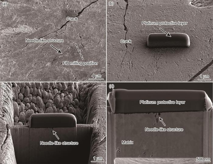
图2
聚焦离子束(FIB)制备含有针状相的TEM试样
Fig.2
TEM specimen preparation for needle-like structure by focused ion beam (FIB)
(a) positioning of the targeted needle-like structure
(b) covering with a platinum protective layer
(c) milling and cutting of the lamella
(d) image of the prepared specimen prior to the removal
2 实验结果
图3为GCr15钢失效轴承疲劳剥落后圆周截面上剥落坑附近组织的OM像。可以看出,剥落坑边缘处存在与之相连的裂纹,并沿剥落坑底部向材料内部扩展。裂纹附近存在大量黑色针状组织,如图3中的箭头所示。与GCr15钢马氏体的基体组织相比,这些针状组织更易被硝酸酒精溶液腐蚀,使其在OM下显示为黑色。需要指出的是,这些呈现为针状的组织并非初始马氏体基体组织中预先存在的相,且其形貌、尺寸及萌生特征等也明显不同于微裂纹。这些针状组织多分布于裂纹附近,且“针”的方向未表现出明显的规律性,与裂纹方向及滚动方向也无确定的位向关系,与碳化物也无明显的相互作用关系。可以判定,这种针状组织是GCr15钢在RCF过程中形成的一种“新相”,本工作中将其简称为“针状相”。
图3
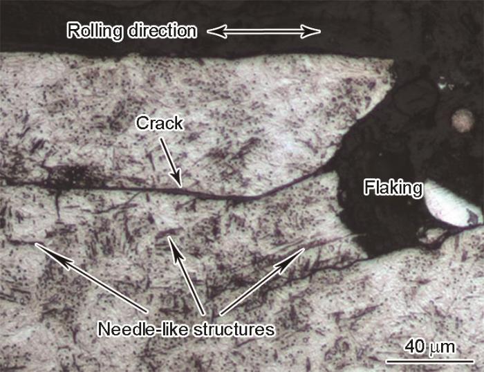
图3
GCr15钢失效轴承表面剥落截面的OM像
Fig.3
OM image of the surface flaking and cracks in the cross section of GCr15 bearing
针状相的微观组织特征如图4a所示。由图可见,针状相在裂纹附近可成束出现,也可孤立存在,其微观形貌为细长的针状,长度为3~8 μm。因其不耐硝酸酒精溶液的腐蚀,经腐蚀处理后的针状相易从初始马氏体基体组织中识别。图4b所示为利用FIB制备的针状相截面的TEM像。可以看出,因硝酸酒精溶液的腐蚀作用,针状相的针状部分截面中形成了距腐蚀表面约100 nm深的凹坑,使得针状相呈现出与微裂纹相似的形态。图4b中位于Pt保护层下的2个V形孔洞分别对应于图4a观察面中所标记的相毗邻的2个针状相。因针状相内部及其周围的微观组织受硝酸酒精溶液的腐蚀作用明显,导致试样腐蚀表面处形成“V”形的腐蚀坑,但在腐蚀坑的底部仍可见针状组织向试样内部延伸。此外,V形腐蚀坑的下方存在多个孔洞,尺寸为100~200 nm,如图4b中的箭头所示。值得注意的是,因这些孔洞距离腐蚀表面较近,存在被酸液腐蚀而扩大的可能。为避免在机理分析时引入这些人为因素的干扰,表征过程中未对这些孔洞及其周围微观组织进行详细分析,而是选择位于其下端区域(图4b中方框中位置)的微观组织及所生成的微观孔洞进行微观结构的表征与解析。
图4

图4
针状相的SEM像及其垂直截面的TEM像
Fig.4
SEM image of the needle-like structure (a) and the bright-field TEM image of the microstructure in the cross section indicated by the dashed line in Fig.4a (b) (The red arrows in Figs.4a and b indicate locations of the needle-like structures for observation, square area in Fig.4b presents the place for detailed microstructural analysis)
图5为与V形腐蚀坑相连的针状相微观组织的TEM分析。从图5a可以看出,针状相呈现为细长条状的典型特征,针状相的微观组织与马氏体基体的微观组织明显不同,其与马氏体基体之间的界面非常明显。针状相内部局部区域存在微观孔洞,且在孔洞周围生成了尺寸为20~50 nm的等轴状纳米晶粒,如图5b所示。为了进一步认清针状相内部结构的微观特征,分别在微观孔洞及其附近区域选取了I、II、III 3个区域进行HRTEM表征,如图5c~e所示。图5d和e证实针状相内部生成了等轴状的纳米晶粒,其快速Fourier变换(FFT)斑点(图5d和e中插图)表明其为α-Fe晶体结构,且等轴晶粒内部存在明显的位错缠结。而从图5c可见,在纳米晶与微观孔洞交界处的FFT斑点(图5a中插图)出现非晶晕环的特征,证明在此区域生成了非晶结构。需要说明的是,无论是等轴状纳米晶还是非晶结构,均不是马氏体基体中的初始微观结构。这些特殊微观结构的生成,意味着针状相是因轴承钢在滚动接触疲劳过程中所施加的循环应力导致其内部微观组织发生退化而形成的。为了进一步验证针状相内部的微观结构,选取针状相截面内的另外2处不同的位置进行选区电子衍射(SAED)和TKD分析,选取区域分别位于针状相截面的上部和底部(图5a虚线框区域P1和P2),结果如图6所示。从SAED花样(图6b和e)中可以看出,所选区域内形成的α-Fe衍射斑点呈同心圆分布,这就意味着在所选区域内存在一定数量且取向不同的α-Fe细晶粒,这也佐证了图5b的结果,即针状相内部形成了取向不同的等轴状铁素体晶粒。TKD的表征结果(图6c和f)也证实,选取区域内已生成等轴状晶粒,而且晶粒的取向随机,说明在此区域发生了再结晶。
图5

图5
针状相内部微观结构的TEM分析
Fig.5
Low (a) and locally high (b) TEM bright-field images of the needle-like structure; HRTEM images of the microstructures in the areas I (c), II (d), and III (e) shown in Fig.5b (The dashed line in Fig.5a indicates the interface between the needle-like structure and martensite matrix, insets in Figs.5c-e show the corresponding fast Fourier transform (FFT) diffractograms of the selected areas inside the dashed squares)
图6
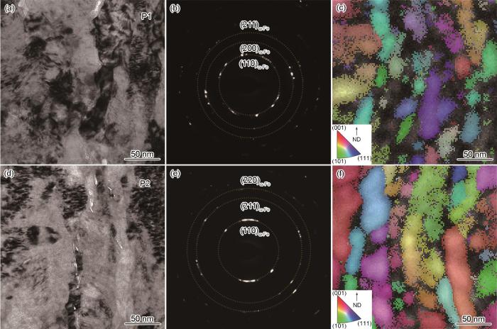
图6
针状相不同位置的TEM明场像、选区电子衍射(SAED)花样和透射菊池衍射(TKD)像
Fig.6
Magnified TEM bright-field images (a, d), corresponding selected area electron diffraction (SAED) patterns (b, e) and transmission Kikuchi diffraction (TKD) images (c, f) of the needle-like structure in the selected region P1 (a-c) and region P2 (d-f) shown in Fig.5a (ND—normal direction)
图7
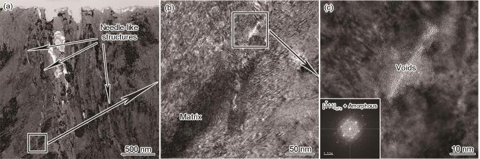
图7
单一针状相内部微观结构的TEM像
Fig.7
TEM bright-field image (a) and HRTEM image (b) of one specific needle-like structure, locally high magnified HRTEM image of the square area indicated in Fig.7b (c) (Inset in Fig.7c shows the corresponding FFT diffractogram)
3 分析讨论
3.1 表面裂纹附近的针状相
由以上结果可知,针状相是轴承钢在RCF过程中生成的一种特殊的微观组织。这种针状相具有细长条状的典型特征,经硝酸酒精腐蚀后的金相组织显示为黑色针状。本工作中观察到的针状相在表面裂纹附近的区域形成,如图4a所示,这就使得针状相极易被误认为是处于萌发阶段的二次裂纹。但针状相并不是裂纹,其内部存在着复杂的微观组织。对其内部微观结构表征与分析后发现,其内部的微观组织与初始马氏体基体组织明显不同。可以确定,这种针状相是轴承钢RCF过程中形成的一种“新相”。
图8

图8
针状相的三维结构示意图
Fig.8
Schematic of the three-dimensional view of the needle-like structure
如前所述,针状相的局部区域存在微观孔洞及非晶态结构,这也是在针状相内部形成的非常特殊的微观结构。事实上,在很多RCF微观组织缺陷中均已观察到过这种非晶态结构[31~34]。虽然对轴承钢RCF过程中非晶结构的来源仍存在多种机理解释[33~35],但普遍观点认为,RCF过程中非晶结构的形成是因局部区域受到严重塑性变形作用而发生的非晶化转变所导致的[34,36]。显然,针状相内部非晶结构的形成与RCF过程中循环接触载荷作用在显微组织局部区域所导致的局部应力密切相关。在本工作所考察的RCF条件下,表面裂纹形成之后会由表层向内斜向扩展,扩展过程中润滑油会进入裂纹而形成“油楔”。在这种情况下,当滚动接触应力作用于“油楔”时,会在形成“油楔”的裂纹面附近的马氏体基体中产生复杂的局部塑性剪切作用。在RCF过程中,这种局部塑性剪切作用会循环作用于马氏体基体,导致马氏体基体的局部组织发生退化而形成薄板状针状组织,即“针状相”。随着RCF的继续进行,这种局部塑性剪切应力的持续作用会进一步导致所形成的针状组织的局部区域与毗邻的马氏体基体之间形成应力集中,当应力超过材料的应力极限时就会在这些应力集中区域形成微观孔洞(如图5a所示)。随着微观孔洞的生成,这些区域的应力集中会进一步加剧,这也是在微观孔洞边缘区域观察到非晶结构的原因。除此之外,在RCF局部应力的作用下,针状相内部微观孔洞周围的退化区域会累积局部应变能而成为高能量位置。随着应变能的持续积累,此区域会发生再结晶而形成等轴状纳米晶粒,如图5b所示。而且,所形成的等轴状再结晶晶粒内部仍存在大量位错,这就表明针状相中形成等轴状纳米晶的区域仍然承受着RCF接触应力的循环作用,这也从侧面证明了针状相形成的驱动力来源。
3.2 针状相与表面裂纹之间的相互作用
由以上分析可知,本工作中所观察到的针状相是在轴承表面裂纹附近形成的一种微观组织缺陷,是轴承钢在RCF过程中发生的马氏体组织退化的形式之一[37~39]。在滚动轴承的RCF过程中,润滑油会沿表面裂纹进入其内部而形成“油楔”,在接触应力的作用下,它会使裂纹面周围的马氏体基体组织承受巨大的局部剪切应力[40~42]。这种局部剪切应力的作用使基体马氏体组织发生了退化,导致了针状相的形成,其形成过程如图9所示。由于表面裂纹具有形状不规则的特点,裂纹附近的应力分布复杂且不具规律性,这就使得针状相的形成位置同样无规律性,但其均在表面裂纹附近的应力影响区域内形成。而且针状相的方向呈多样性,与裂纹方向无确定的位向关系。
图9

图9
滚动接触疲劳过程中针状相近邻表面裂纹形成的示意图
Fig.9
Schematics of the needle-like structure formation close to the surface crack during rolling contact fatigue (RCF)
如前所述,针状相中生成了许多微观孔洞。这些微观缺陷的出现会加剧其邻近区域内的应力集中,不仅会使形成的微观孔洞成为裂纹萌生的潜在位置,还为裂纹的扩展提供便利通道。针状相薄板状的三维形貌会使裂纹易于沿针状相与马氏体基体间的界面传播,大大提高裂纹的扩展速率。由于针状相毗邻表面裂纹形成,针状相的形成会大大促进二次裂纹的增殖及传播,使得轴承接触表面发生疲劳剥落的速率加快。可见,针状相的形成为轴承钢RCF过程中表面裂纹的扩展及二次裂纹的萌生提供了一种新的途径。
4 结论
(1) GCr15钢轴承的滚动接触疲劳过程中,在表面诱发的裂纹附近会形成一种针状相。这种针状相经硝酸酒精腐蚀后的金相组织显示为黑色针状,容易与裂纹混淆。针状相的形成源自于滚动接触疲劳过程中接触应力作用于表面裂纹面而在其附近产生的局部应力。
(2) 针状相是轴承钢滚动接触疲劳过程中发生的一种特殊的马氏体组织退化形式,具有细长条状的典型特征,三维形貌为薄板状形态。针状相内部局部位置存在微观孔洞,并在其周围形成了非晶结构和等轴状铁素体晶粒,主要是由局部区域所承受的巨大应力以及伴随发生的再结晶所致。
(3) 针状相是因表面裂纹附近的局部应力诱发而形成,而针状相的形成会促进表面裂纹的增殖及传播,针状相的形成与表面裂纹的扩展彼此促进。针状相内部生成的微观孔洞为二次裂纹的萌生提供了潜在位置,同时为裂纹的扩展提供便利通道,加速轴承接触表面疲劳剥落的发生。针状相的形成为轴承钢滚动接触疲劳过程中表面裂纹扩展及二次裂纹萌生提供了一种新途径。
参考文献
Relationship of inclusions and rolling contact fatigue life for ultra-clean bearing steel
[J].
The cleanliness of bearing steels produced in China has been greatly improved due to the significant progress in the steelmaking technologies in the past decade, leading to their total oxygen (T.O.) contents lowered to no more than 6×10⁻⁶. Under such a high cleanliness, it is then expected that the influence of non-metallic inclusions on fatigue property should be different from the previous knowledge, because both the size and quantity of inclusions are reduced greatly. Therefore, both inclusions and fatigue properties for three ultra-clean GCr15 (100Cr6) bearing steels containing T.O. around 6×10⁻⁶, which were manufactured via different industrial production processes, were studied for this purpose. First, inclusions were characterized by ASPEX SEM and then statically analyzed by the statistics of extreme values (SEV) and the generalized Pareto distribution (GPD). Next, their rolling contact fatigue lives (RCF) L10 and L50 were measured by flat washer tests. Only the largest inclusion in each sample is required for predicting the characteristic sizes of maximum inclusion (CSMI) for the three steels using the SEV method. The calculated CSMIs, however, are not consistent with the variation of either L10 or L50, indicating they are not relevant. In contrast, the types of inclusions above threshold (u) size can be classified and their number density of inclusions quantified when the GPD method is employed. In particularly, the CSMIs of different types of inclusions can be determined. In this case, it has been found that the CSMI of TiN inclusion, which is the most dangerous for initiating cracking, is in a good agreement with the low probability rolling fatigue life (L10), suggesting that they are very correlated. This, however, cannot explain the variation of high-probability fatigue life (L50). Instead, the density of total inclusions also played an important role on the L50 of ultra-clean bearing steels in addition to the CSMI of TiN inclusions. This is reasonable because cracking shall be initiated at not only the most dangerous TiN inclusion during the early failure but also some other highly dense inclusions particularly during the late failure. Therefore, it is then concluded that the L10 is much more related to the CSMI of most dangerous TiN inclusion; whilst the L50 is strongly affected by the number density of total inclusions.
超洁净轴承钢中夹杂物与滚动接触疲劳寿命的关系
[J].以3种不同工艺工业生产的总O含量均≤6×10-6的超洁净GCr15轴承钢为研究对象,通过推力片实验测试这3种钢的滚动接触疲劳寿命并获得额定寿命(L10)和中值寿命(L50),通过ASPEX扫描电镜获得各工艺下的夹杂物样本数据并进行统计分析,使用极值法(SEV)和广义Pareto分布法(GPD)估算出样品中最大夹杂物特征尺(CSMI),然后将其与实测L10和L50进行对比和分析。结果表明,SEV法仅检测每个样品的最大夹杂物,无法通过其获得的CSMI来合理解释3种钢L10和L50的变化,2者之间相关性较差;而GPD法分析夹杂物时,需要对阈值尺寸以上的所有夹杂物进行表征和统计分析,可以获得夹杂物的数量密度以及不同类型夹杂物的CSMI,GPD法所预测出的最危险类型TiN夹杂物的CSMI可以合理解释L10的变化,2者之间有较好相关性,但无法据此解释L50的变化;但将总的夹杂物数量密度与TiN夹杂物最大特征尺寸相结合,能合理解释3种钢的L50差异,这是因为当更多样品失效时,裂纹萌生位置将不再仅仅局限于最危险类型夹杂物。因此,最危险类型夹杂物的CSMI与超纯净轴承钢中的早期疲劳失效的L10相关性最强,而夹杂物的数量密度对高概率的中值疲劳寿命L50也有重要影响。
Dark etching regions under rolling contact fatigue: A review
[J].Bearing performance depends on the ability of steel to cope with a large number of stress cycles. Long bearing lives are possible because the microstructure of bearing steel has excellent resistance to Rolling Contact Fatigue (RCF). Nevertheless, it is observed that the microstructure suffers changes in the region where the maximum Hertzian contact stress occurs. Here we give an overview of the present knowledge in the area of the formation of dark etching regions (DERs) during RCF. Factors that influence the formation of DERs, various types of characterisation techniques, and the observations made in the literature are discussed. In addition, the applicability of several proposed simulation models of the formation of DERs is discussed.
Rolling contact fatigue behavior of an ultrahigh carbon steel
[J].With the development of modern industrial equipment and the requirement in energy conservation and emission reduction, the traditional high carbon and high chromium steel which is widely used as bearing material cannot meet these demands. Therefore, it is of paramount importance to exploit novel materials used as bearings with long life. In recent years, some new techniques have been used to improve the bearing life, such as physical vapor deposition (PVD), chemical vapor deposition (CVD) and plasma immersion implantation and so on. All these techniques are attempting to increase the surface hardness of the bearing. Though the bearing life has been extended to some extent, the application range of these techniques is limited by the price factor and the dimensions of components. Ultrahigh-carbon steels (UHCSs) have been studied for many years, and they possess outstanding mechanical properties and wear resistance. Therefore, it is interesting to explore the probability whether UHCSs can be used in the bearing application. It is well known that if bearings are well assembled, lubricated and loaded, rolling contact fatigue (RCF) is the main failure form. Accordingly, the evaluation of the resistance to RCF is of paramount importance for bearing materials. The RCF properties of UHCSs have never been studied in the past decades. Therefore, in this work, the RCF behavior of a UHCS with 1.29%C (mass fraction) was investigated in well lubricated conditions, using a flat washer-type RCF tester. In order to shorten the testing time, the maximum Hertzian stress was set as 4400 MPa. For comparison, the RCF lives of conventional GCr15 and SKF3 bearing steels were also tested under the same conditions. The results showed that the rated life L10 of the UHCS was 2.14 and 1.81 times longer than those of the GCr15 and SKF3 steels, respectively. Since more spherical residual carbide particles could be used to retard the grain growth during austenitization for the UHCS, the prior austenite grain size of the UHCS was only 6.91 μm. However, the prior austenite grain sizes of the GCr15 and SKF3 steels were 13.52 and 11.41 μm, respectively. Therefore, the average size of martensite plate of the UHCS was approximately half of those of the GCr15 and SKF3 steels. Finer grains were expected to retard the crack initiation and propagation, and then the RCF life would be prolonged. On the other hand, the carbon content and the volume fractions of precipitates in the martensite plates of the quenched and tempered UHCS were both higher than those of the GCr15 and SKF3 steels. These factors made the UHCS harder than GCr15 and SKF3 steels, which was beneficial for the improvement of RCF life.
一种超高碳钢的滚动接触疲劳研究
[J].研究了一种C含量为1.29% (质量分数)的超高碳钢在最大Hertzian应力4400 MPa, 良好润滑条件下的滚动接触疲劳行为, 同时测试了传统GCr15和SKF3高碳铬轴承钢的滚动接触疲劳寿命以作为对比. 结果表明, 相同条件下, 超高碳钢的额定寿命(L10寿命)分别是GCr15钢和SKF3钢的2.14和1.81倍. 超高碳钢的原奥氏体平均晶粒尺寸为6.91 μm, 仅约为GCr15和SKF3钢的一半. 同时, 淬回火态超高碳钢的硬度为64.5 HRC, 高于GCr15和SKF3钢.
A unified theory for microstructural alterations in bearing steels under rolling contact fatigue
[J].
A review of rolling contact fatigue
[J].
An experimental and theoretical study of hybrid bearing micropitting performance under reduced lubrication
[J].
Research progress of rolling contact fatigue of bearing steels
[J].
轴承钢滚动接触疲劳研究进展
[J].
Dry and lubricated wear of rail steel under rolling contact fatigue—Wear mechanisms and crack growth
[J].
Microstructures and rolling contact fatigue behaviors of 17Cr2Ni2MoVNb steel under combined ultrasonic surface rolling and shot peening
[J].
Observation of subsurface rolling contact fatigue cracks in silicon nitride and comparison of their location to Hertzian contact subsurface stresses
[J].
Main failure mode of oil-air lubricated rolling bearing installed in high speed machining
[J].
Propagation of surface initiated rolling contact fatigue cracks in bearing steel
[J].
The tribo-fatigue damage transition and mapping for wheel material under rolling-sliding contact condition
[J].The purpose of this work is to construct a tribo-fatigue damage map of high-speed railway wheel material under different tangential forces and contact pressure conditions through JD-1 testing equipment. The results indicate that the wear rate of the wheel material varies with tangential force and contact pressure. The wear mapping of the wheel material is constructed and divided into three regions: slight wear, severe wear, and destructive wear, based on the wear rate under each test condition. With an increase in tangential force and contact pressure, the maximum crack length and average crack length of the wheel material increases. According to the surface damage morphologies and corresponding statistical results of average crack length of wheel material under each experiment condition, a tribo-fatigue damage map is constructed and divided into three regions: slight fatigue damage region, fatigue damage region, and severe fatigue damage region. Fatigue cracks initiate on the wheel specimen surface. Some cracks may propagate into material and fracture under cyclic rolling contact; some cracks may grow into inner material with a certain depth, and then turn toward the surface to form material flaking; some cracks may always propagate parallel to the wheel roller surface.
Analysis of contact fatigue crack growth using twin-disc tests and numerical evaluations
[J].
Fatigue crack growth in bearing steel under cyclic mode II + static biaxial compression
[J].
Effect of wear on rolling contact fatigue crack growth in rails
[J].
A fracture mechanics analysis of asperity cracking due to sliding contact
[J].
Hard turning versus grinding—The effect of process-induced residual stress on rolling contact
[J].
Experimental and numerical investigation on fatigue crack growth behavior of commercial pure titanium under I-II mixed mode loading at negative load ratios
[J].
Experimental and numerical investigation on fracture behavior of I-II mixed mode crack for commercially pure titanium
[J].
Cracks on mixed mode loading—Theories, experiments, simulations
[J].
Gigacycle rolling contact fatigue of bearing steels: A review
[J].
Experimental study of I + III mixed mode fatigue crack transformation propagation
[J].
Analysis of surface crack growth under rolling contact fatigue
[J].
Investigating fluid penetration of rolling contact fatigue cracks in rails using a newly developed full-scale test facility
[J].
An updated review: White etching cracks (WECs) and axial cracks in wind turbine gearbox bearings
[J].The actual service life of wind turbine gearboxes is often well below the desired 20 years. One of the prevalent failure modes in gearbox bearing raceways is white structure flaking (WSF) in as little as 6–24 months of operation by the formation of axial cracks and white etching cracks (WECs) with associated microstructural change called white etching areas (WEAs). Despite these failures having been observed for two decades in various industries, the drivers and mechanisms for their formation are still highly contested. Discussed in this review are methods for searching and analysing WECs, mechanisms for WEA microstructural change, WEC initiation and propagation theories, WSF formation drivers and finally technologies and processes offering resistance to WSF. This updated review serves as a recap, comprehensive update on findings, current focus areas and remaining challenges.
Pitting formation due to surface and subsurface initiated fatigue crack growth in contacting mechanical elements
[J].
Fatigue crack initiation and propagation under cyclic contact loading
[J].
Microstructural changes and crack initiation with white etching area formation under rolling/sliding contact in bearing steel
[J].
A FIB/TEM study of butterfly crack formation and white etching area (WEA) microstructural changes under rolling contact fatigue in 100Cr6 bearing steel
[J].
Phase transformation in the subsurface of case carbonitrided bearing steels under rolling contact fatigue
[J].
Deformation-induced amorphization and austenitization in white etching area of a martensite bearing steel under rolling contact fatigue
[J].
Microstructural evolution in bearing steel under rolling contact fatigue
[J].
Extremely hard amorphous-crystalline hybrid steel surface produced by deformation induced cementite amorphization
[J].
Further understanding of rolling contact fatigue in rolling element bearings—A review
[J].
Strain-induced martensite decay in bearing steels under rolling contact fatigue: Modelling and atomic-scale characterisation
[J].
Multiscale study on the dark-etching region due to rolling contact fatigue of 0.57C-bearing steel
[J].
The role of lubricating fluid pressurization and entrapment on the path of inclined edge cracks originated under rolling-sliding contact fatigue: Numerical analyses vs. experimental evidences
[J].
A novel experimental procedure to reproduce the load history at the crack tip produced by lubricated rolling sliding contact fatigue
[J].
