


M50轴承钢是一种二次硬化马氏体钢,广泛应用于航空发动机主轴轴承的制造。与常见的GCr15轴承钢相比,M50轴承钢是一种高碳高合金钢,除含Cr外还含有一定量的强碳化物形成元素Mo和V,导致其在冶炼过程中由于合金元素的偏析形成大量沿晶界呈网状分布的一次碳化物,尺寸可达几十微米[1]。碳化物是硬脆相,与基体的物理性质存在显著差异,在后续锻轧等热加工过程中由于变形不协调而导致显微孔洞的产生。孔洞的存在不仅会导致M50轴承钢在热变形过程中开裂,严重危害其热加工性能,也会使其服役时的力学性能显著降低[2~4]。对M50轴承钢热变形过程进行系统研究,掌握孔洞的产生条件和分布规律及后续处理对孔洞愈合过程的影响,对提高其热加工性能和力学性能具有重要意义。
长期以来,众多学者[5~9]对材料在变形过程中孔洞的产生和闭合行为进行了大量的研究,Yu等[10]发现在不锈钢冷轧过程中,孔洞易沿轧制方向在夹杂物与基体的界面处萌生,且夹杂物尺寸越大,孔洞长度越长。Cheng等[11]通过有限元方法模拟了板坯轧制过程中的应变分布,发现夹杂物与周围基体在塑性变形能力上的差异是导致裂纹孔洞产生的主要原因,硬度高、难变形的夹杂物更易诱发裂纹萌生。除了夹杂物尺寸、硬度等物理性质的影响,材料的变形工艺也会影响孔洞的产生。Cheng等[12]研究了3种钢在不同轧制温度下夹杂物的变形,发现只有在临界温度以下,夹杂物和基体之间才会形成孔洞,且轧制温度越低,形成的孔洞越长。还有相关研究[13~17]集中于轧制下压量、摩擦因数、夹杂物位置等因素对孔洞产生的影响。当这些孔洞位于轧制过程中变形量较大的次表层时,可通过进一步的塑性变形实现闭合;当孔洞位于板坯中间时,由于相对变形量较小,则很难通过变形愈合;较高的轧制温度也可以促进孔洞的自愈合[18,19]。这些研究仅仅局限于轧制过程中较小尺寸的夹杂物诱导产生的孔洞,关于材料中大尺寸第二相对孔洞产生的影响则鲜有报道。
本工作通过一系列的热模拟实验系统研究了变形条件对M50轴承钢中孔洞产生行为的影响,揭示碳化物诱导孔洞产生的机理,在后续保温处理过程中通过原位实验观察保温前后孔洞的形态,分析保温处理对孔洞的愈合作用,为轴承钢热加工工艺的制定提供参考。
1 实验方法
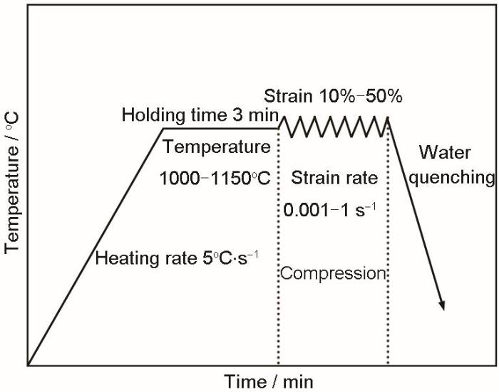
实验材料选取退火态M50轴承钢铸态试样,化学成分(质量分数,%)为:C 0.8,Cr 4.01,Mo 4.21,V 1.0,Ni 0.12,Mn 0.21,Si 0.2,S 0.001,P 0.006,O 0.0003,Fe余量。将铸态样品加工成直径8 mm、长12 mm的圆柱试样。具体工艺如图1所示,首先利用Gleeble3500热模拟试验机在真空条件下以5℃/s的速率升温到变形温度,并在该温度下保温3 min以确保变形前样品温度的均匀性,之后在不同变形条件下(应变速率0.001~1 s-1,变形温度1000~1150℃,应变10%~50%)进行热压缩,将变形后的样品水淬至室温后用线切割沿样品轴向切开以进行后续的处理分析。
图1
将切开后的样品进行机械研磨、抛光并利用4% (体积分数)硝酸酒精腐蚀,然后用AxioCam MRc5金相显微镜(OM)、MIRA3场发射扫描电子显微镜(SEM)及其附带的ULTIM MAX型X射线能谱仪(EDS)进行显微组织观察和成分分析,用image-pro plus软件统计不同变形条件下孔洞的数量密度及体积分数,其中选取至少10个视场进行统计分析,并取10个视场下孔洞体积分数与数量密度的平均值作为统计结果,以此来对比不同条件下孔洞的产生情况。采用振动抛光方式制备电子背散射衍射(EBSD)样品,采用MIRA3型SEM及其附带的C-NANO型EBSD探头来分析不同碳化物的Kikuchi花样。利用Agilent G200纳米压痕系统,在9.6 mN力的作用下对基体和不同碳化物进行纳米压痕测试以测量不同区域的显微硬度。将变形后的样品在850℃下保温不同时间,统计不同保温时间后孔洞的总面积来分析保温处理对孔洞的影响,采用FEI Nova 450型SEM及其配备的MINI-MTS2000@HT原位高温拉伸设备对保温中的样品进行实时SEM观察,用以分析孔洞的愈合情况。
2 实验结果与讨论
2.1 原始样品的显微组织分析
M50轴承钢铸态样品的原始微观组织如图2所示。由于材料内部合金元素偏析的影响,碳化物在晶界附近析出,形成网状结构,同时观察到原始铸态组织中并无明显孔洞的存在。图3a为原始铸态样品的SEM像。可以看出,材料内部碳化物尺寸在几微米到几十微米范围,呈棒状、网状、球状形态分布在铁素体基体中,对原始铸态组织进行面扫描分析可发现碳化物内部的元素分布存在一定的差异(图3b~e)。对图中大尺寸一次碳化物进行EBSD点分析,结果发现原始铸态样品中的碳化物呈现出M2C (图3f)与MC (图3g)型碳化物Kikuchi花样,由此可知铸态样品中的大尺寸一次碳化物主要分为M2C与MC型碳化物,这与Du等[23]的报道一致。对2种碳化物进行EDS分析发现,M2C型碳化物主要由Mo与C组成(图3h),说明其为Mo2C;MC型碳化物则含有较多的C与V元素(图3i),说明该碳化物为VC。此外也可以看出,不同种类碳化物在SEM下呈现出不同的衬度,相对M2C碳化物来说,MC碳化物的衬度更深,这种衬度的差异是MC型碳化物V元素富集的结果[24]。
图2
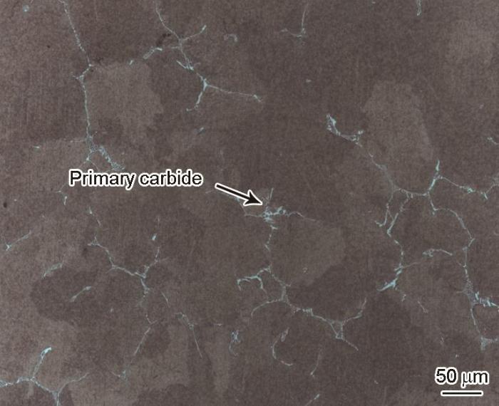
图2
M50轴承钢原始铸态组织的OM像
Fig.2
OM image of original as-cast microstructures of M50 bearing steel
图3
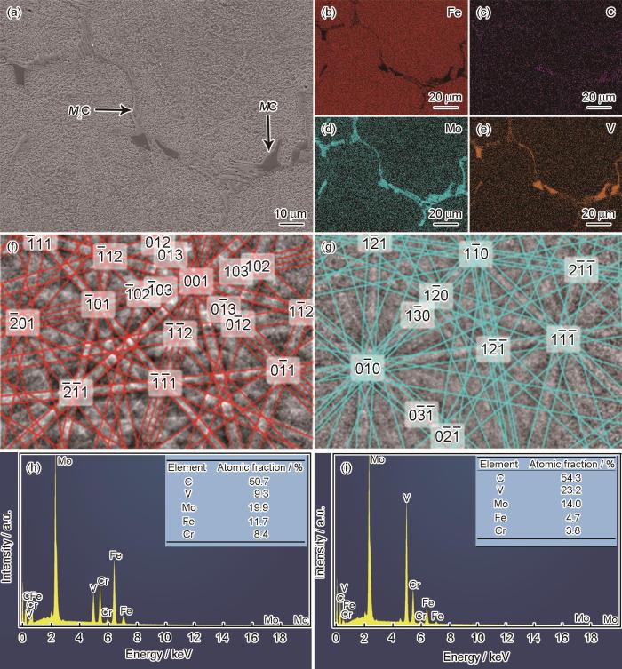
图3
M50轴承钢原始铸态样品内部显微组织的SEM像、EDS结果及碳化物的Kikuchi花样
Fig.3
SEM image (a) and EDS element distribution maps of M50 bearing steel (b-e), Kikuchi patterns of M2C (f) and MC (g), and EDS results of M2C (h) and MC (i)
2.2 热加工过程中孔洞的形成
对M50轴承钢原始铸态样品进行热变形处理(1100℃、0.1 s-1和30%),处理后的OM和SEM像如图4所示。可见,材料在压缩载荷作用下发生了较大的塑性变形,变形后原始样品的碳化物网状结构被破坏(图4a),材料内部的碳化物垂直于塑性变形方向呈带状分布,与此同时在变形应力的作用下,碳化物发生断裂破碎,其周围开始产生较为明显的孔洞(图4b黑色区域),这种孔洞常位于碳化物附近,其面积往往不超过3 μm2,这与凝固过程中由于凝固收缩和气体析出所形成的可达数百微米的缩孔或气孔有一定区别[25~27]。对原始样品中碳化物与基体进行纳米压痕硬度测试,结果表明,基体、MC和M2C型碳化物的平均硬度分别为15.60、41.36和27.49 GPa。对于原始铸态样品来说,碳化物的存在会导致碳化物与基体界面的不连续性,在压缩载荷的作用下会产生局部非均匀流动。故随着变形过程的进行,可能发生碳化物与基体界面的脱黏、滑动和分离,而且由于碳化物与基体的硬度存在一定的差异,在同样的变形应力作用下基体与碳化物不能同时协调变形,促使碳化物与基体的界面受法向拉应力,从而诱导孔洞的产生[15]。
图4
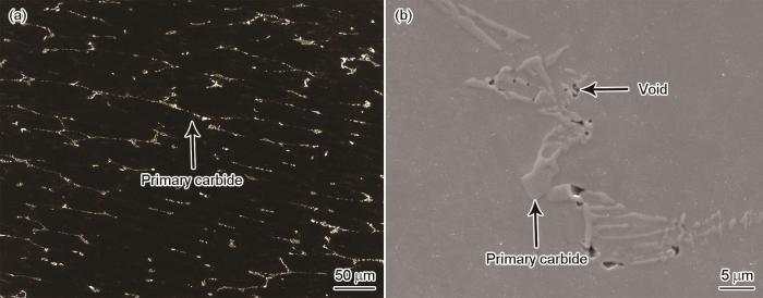
图4
M50轴承钢铸态样品经1100℃、0.1 s-1和30%热变形处理后的OM和SEM像
Fig.4
OM (a) and SEM (b) images of the M50 bearing steel after hot deformation treatment at 1100oC, 0.1 s-1, and 30%
图5
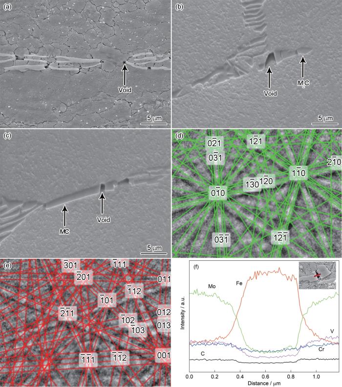
图5
M50轴承钢经1100℃、0.1 s-1和30%热变形处理后样品内部不同位置处孔洞的SEM像,MC和M2C碳化物的Kikuchi花样,以及碳化物周围孔洞的EDS线扫描结果
Fig.5
SEM images of voids at different positions inside the M50 bearing steel after hot deformation treatment at 1100oC, 0.1 s-1, and 30% (a), and around different carbides (b, c), Kikuchi lines of MC (d) and M2C (e), and EDS line scan analyses of void (Inset shows the position of the line scan around the void) (f)
2.3 变形工艺对孔洞产生的影响
2.3.1 应变速率对孔洞产生的影响
图6a~d为M50铸态样品在1100℃变形温度、50%应变、不同应变速率下的显微组织,图6e为不同条件下碳化物周围孔洞体积分数和数量密度的统计结果。在0.001和0.01 s-1的应变速率下,较低的变形速率导致较长的变形时间,组织有充足的时间进行动态回复及再结晶,因此低应变速率条件下的晶粒更为细小,此外在压缩载荷的作用下碳化物网状结构被破坏而呈条带状聚集式分布,只有一小部分碳化物保留网状碳化物的特征,此时碳化物周围的孔洞数量较少(图6a和b)。当应变速率增加到0.1 s-1时,可在碳化物周围发现少量孔洞,随着应变速率提高孔洞数量与尺寸随之增加(图6c)。随应变速率增加到1 s-1,较高的应变速率导致较短的变形时间,此时可发现大量长条状碳化物发生开裂现象,孔洞的数量和尺寸进一步增加,此外随应变速率增加至1 s-1时发现一些较大孔洞的存在,一部分孔洞也呈现出向裂纹发展的趋势(图6d)。从图6e的统计结果可以看出,对于不同的应变速率(0.001~1 s-1),孔洞的体积和数量随应变速率的增加均呈上升趋势,1 s-1的应变速率下变形孔洞体积分数和数量密度均达到最大,分别为0.149%和2188.2 mm-2。
图6
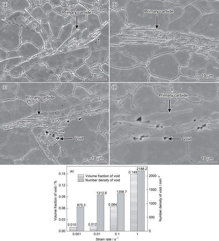
图6
变形温度1100℃和应变50%时不同应变速率下热变形后M50轴承钢中碳化物周围孔洞的SEM像及孔洞的体积分数和数量密度统计结果
Fig.6
SEM images of voids around carbides in M50 bearing steel after hot deformation at strain rates of 0.001 s-1 (a), 0.01 s-1 (b), 0.1 s-1 (c), and 1 s-1 (d) at temperature of 1100oC and strain of 50%, and statistical results of the volume fraction and number density of voids (e)
在材料热压缩过程中,随着变形程度的增加,位错大量增殖,与此同时也伴随着动态回复与动态再结晶的发生。当应变速率较小时,有足够的时间来进行动态回复与动态再结晶,动态软化起主导作用,材料的流变应力与变形抗力也相对较低;当应变速率较大时,材料没有足够时间进行动态回复与动态再结晶,此时加工硬化所起的作用大于动态软化,材料的流变应力与变形抗力也随之提高[28]。压缩过程中,在较软的基体与较硬脆的碳化物附近产生强烈的应力集中,从而促使碳化物破碎。当变形抗力较大时,应力更集中于碳化物附近,从而加剧了碳化物破碎现象,在破碎的碳化物附近形成更多的孔洞。而当变形抗力较小时,应力集中于基体附近,释放了一部分碳化物硬脆相的应力集中,碳化物破碎的趋势减弱,碳化物周围的孔洞数量和尺寸也随之减少[29]。
2.3.2 变形温度对孔洞产生的影响
将M50铸态样品在不同变形温度下以0.1和1 s-1的应变速率进行应变为50%的压缩变形,其变形后的组织如图7所示。图8为不同变形温度下碳化物周围孔洞体积分数及数量密度的统计结果。对于0.1和1 s-1应变速率下的2组变形样品,在1000℃变形时,原始铸态组织的碳化物网络被破坏,碳化物沿垂直于变形方向被拉长,发生了破碎断裂现象,并在断裂的碳化物周围产生大量的孔洞,此时孔洞分布的数量较多且尺寸也较大(图7a和b)。当变形温度升高到1050℃,孔洞的数量及尺寸均有所减少(图7c和d)。对于0.1 s-1应变速率下的变形样品来说,变形温度升高到1100和1150℃时,孔洞的数量与面积均大幅减少,很难在碳化物附近发现孔洞的产生(图7e和g)。而对于1 s-1应变速率下的变形样品,在1100℃的变形温度下,仍可在部分碳化物附近发现孔洞(图7f);随变形温度升高到1150℃,孔洞也完全消失(图7h)。这是由于随应变速率的增加,碳化物与基体交界处应力集中增强从而促进碳化物破碎产生孔洞。总体而言,在2个应变速率下,孔洞的数量与尺寸都呈现出随变形温度的降低而增加的趋势(图8),这与Luo[15]的研究结果相类似。图8的统计结果表明,在不同温度下(1000~1150℃)变形时,较低温度下会形成较多的孔洞,1150℃变形时孔洞数量大幅减少,1000℃变形时产生的孔洞体积分数最多,可达0.229%。
图7
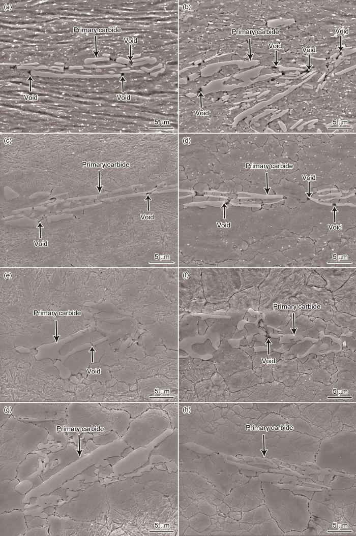
图7
应变50%、应变速率0.1和1 s-1时不同变形温度下热变形后M50轴承钢中碳化物周围孔洞的SEM像
Fig.7
SEM images of voids around primary carbides in M50 bearing steel after hot deformation at strain rates of 0.1 s-1 (a, c, e, g) and 1 s-1 (b, d, f, h) with temperatures of 1000oC (a, b), 1050oC (c, d), 1100oC (e, f), and 1150oC (g, h) at strain of 50%
图8
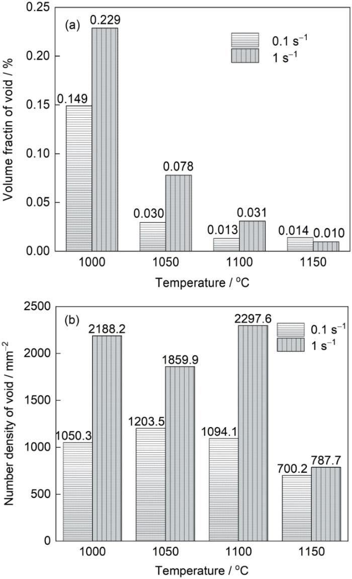
图8
应变50%、应变速率0.1和1 s-1时不同变形温度下孔洞的体积分数及数量密度
Fig.8
Statistical results of the volume fraction (a) and number density (b) of voids at different deformation temperatures with strain of 50%, and strain rates of 0.1 and 1 s-1
M50铸态样品在较低温度下进行塑性变形时,金属的流动性较差,材料变形时会产生较大的变形抗力,碳化物与基体附近更剧烈的应力集中促使碳化物更易断裂,从而促使孔洞的产生。在较高的温度变形时,原子的振动加剧,迁移能力增强,使滑移带上的位错更易发生滑移攀移运动,削弱了应变时由于位错增殖所引起的强化作用,一定程度上促使材料更易发生动态回复与动态再结晶,加强了动态软化的作用,与此同时高温下金属的塑性变形能力随之增大,减弱了压缩变形时碳化物与基体附近的应力集中,故碳化物周围的孔洞体积分数也随之减少。对于在1100℃、1 s-1应变速率下应变为50%的样品,如图7f所示,在碳化物两侧仍能发现一些细小的微孔,这是由于高温下材料发生塑性变形,碳化物顶部和底部的基体的塑性应变大于碳化物自身的塑性应变,这种塑性应变的差异导致基体与碳化物界面发生相对位移,从而促使碳化物两侧孔洞的产生[11]。此外,相关研究[30]表明,当发生塑性变形时夹杂物周围会产生一定数量的锥形孔洞,但在高温条件下,流动的金属会填充一部分锥形孔洞。这也就说明在较高温度下变形时,碳化物周围的孔洞也能得到一定程度的填充,故在1150℃下的变形样品碳化物周围孔洞的数量大幅减少。
2.3.3 变形量对孔洞产生的影响
为了研究不同变形程度下碳化物周围孔洞的产生情况,对M50铸态样品在1100℃、0.1和1 s-1的条件下分别进行不同应变的热变形处理,并统计了不同变形量下碳化物周围孔洞体积分数与数量密度的变化情况,如图9所示。结果表明,在0.1 s-1应变速率下变形10%时,仅在部分碳化物周围发现数量很少的微孔洞,这是由于此时变形量较低,材料仍保持一部分铸态组织下的碳化物网状结构,晶界附近的网状碳化物未充分破碎(图9a);当变形量提高到30%时,碳化物网状结构破坏,在破碎碳化物周围形成一定数量的孔洞(图9c);当变形量增加到50%时,碳化物周围看不到孔洞的存在(图7e)。而在1 s-1应变速率下变形10%时,应变速率的提高加剧了碳化物破碎现象,导致在部分碳化物附近形成孔洞,其数量与尺寸相对0.1 s-1应变速率的变形样品也有所提高(图9b);而变形量提高到30%时,受应变速率提高与变形量增加的双重作用,碳化物破碎进一步加剧,碳化物周围孔洞数目也进一步增加(图9d);随变形量增加到50%,孔洞数量大幅减少,但相对0.1 s-1应变速率的变形样品也有所提高(图7f)。图9e和f的统计结果表明,对于不同的应变(10%~50%),变形30%时产生了较多数量的孔洞,此时1 s-1应变速率下孔洞的体积分数也最多,可达0.193%。
图9
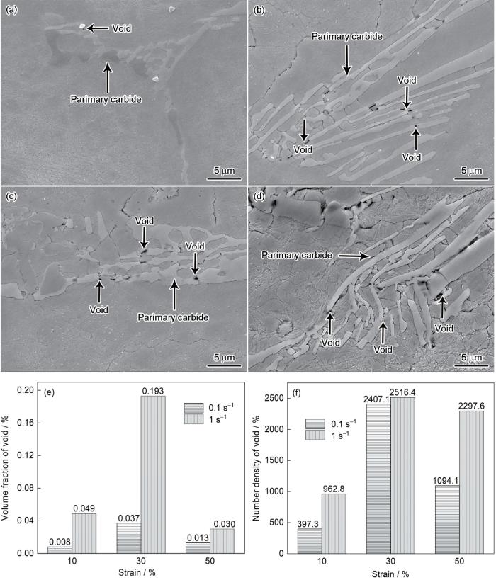
图9
M50轴承钢在1100℃变形不同程度后碳化物周围孔洞的SEM像及孔洞的体积分数和数量密度统计结果
Fig.9
SEM images of voids around carbides in M50 bearing steel after hot deformation at strains of 0.1 s-1 (a, c) and 1 s-1 (b, d) for strains of 10% (a, b) and 30% (c, d); and statistical results of volume fraction (e) and number density (f) of voids
碳化物的断裂概率取决于其尺寸、形状、加载条件等因素,施加的载荷主要是通过影响碳化物内部的应力分布从而影响碳化物的断裂几率[31]。施加的载荷大小则与材料的变形程度密切相关,当变形量增加,材料内部位错数量密度增加,在位错运动时位错之间的交互作用促使位错缠结、位错割阶等现象的发生,这就进一步阻碍了位错的运动,材料的变形抗力增加,此时只有施加更大的应变载荷才能促使材料发生进一步变形,从而促使碳化物断裂的概率提高,碳化物破碎形成的孔洞数目也随之增加。此外碳化物破碎需要达到一定的临界应变[32],材料在载荷的作用下进行压缩变形时,由于材料每个微区的情况不同,材料整体各个区域不能达到一致的均匀协调变形,故当材料的变形量达到一定程度时,才能促使碳化物达到一定的临界应变。此时再进行进一步的变形时碳化物就不再与周围基体进行协调一致的变形,这就会导致碳化物或碳化物与基体的交界处产生裂纹源,从而促进碳化物的破碎断裂,引起碳化物周围孔洞数量的增加。而随着变形量的进一步增加,碳化物周围的孔洞会发生所谓的“自焊”现象[15],就是说碳化物孔洞上下方的金属受塑性变形的作用在一定程度上会修复填充已经形成的孔洞,孔洞的体积分数会随着材料的进一步变形而有所减小。在本工作中,相对30%变形量的样品,变形程度为50%的样品内部孔洞受周围基体的填充作用,其尺寸和数目相对有所减少,这也与Luo[15]的相关研究结果一致。
2.4 保温处理对孔洞愈合的影响
针对上述各种变形条件下产生的孔洞,采用长时间保温可以通过扩散作用使孔洞得到一定程度的修复,甚至完全愈合孔洞。为了更加明显地观察保温前后孔洞的变化,选取在温度为1100℃、应变速率为1 s-1的条件下变形50%的样品进行分析,采用工程上850℃的球化退火温度对变形后样品保温1 h处理并进行原位SEM分析。图10为保温前后碳化物及周围孔洞的变化。在保温过程中,碳化物中的合金元素会从薄层尖端、细颈等曲率半径较小的地方向碳化物表面一些曲率半径较大的地方扩散,因此受保温处理的影响,样品内部的碳化物发生球化[33],与此同时,可以观察到保温处理后孔洞率先在孔洞与基体交界处愈合,保温处理可有效减少孔洞面积,促使孔洞愈合。
图10
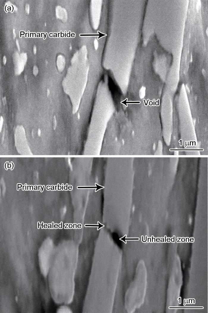
图10
热变形样品在850℃下保温1 h前后样品的SEM像
Fig.10
SEM images of thermal deformation sample before (a) and after (b) soaking at 850oC for 1 h
孔洞愈合的演变受晶格扩散、晶界扩散、表面扩散、晶粒长大和碳化物析出等多重因素的影响[34~38],由此导致保温前后孔洞周围元素分布会存在一定的差异,为分析保温处理后孔洞周围的元素分布情况,对保温后孔洞及周围基体碳化物进行EDS线扫描分析,结果如图11所示。图11a为保温后发生愈合的孔洞,其中线扫区域从A至D依次由基体区(MZ)、孔洞区(VZ)、愈合区(HZ)与基体区(M'Z) 4个部分组成,孔洞未愈合部分具有较多的Fe元素,合金元素和C元素则较低,与前文所述的孔洞特征一致,而已愈合部分的孔洞C元素含量则大幅上涨,而且其他合金元素的含量也显著增加(图11b)。图11c中的线扫区域从E至G依次分为碳化物区(CZ)、愈合区(H'Z)与碳化物区(C'Z) 3个部分,其中愈合区的C元素及V、Mo元素含量相对周围碳化物含量较低,而Cr元素含量则要高于周围的碳化物。
图11
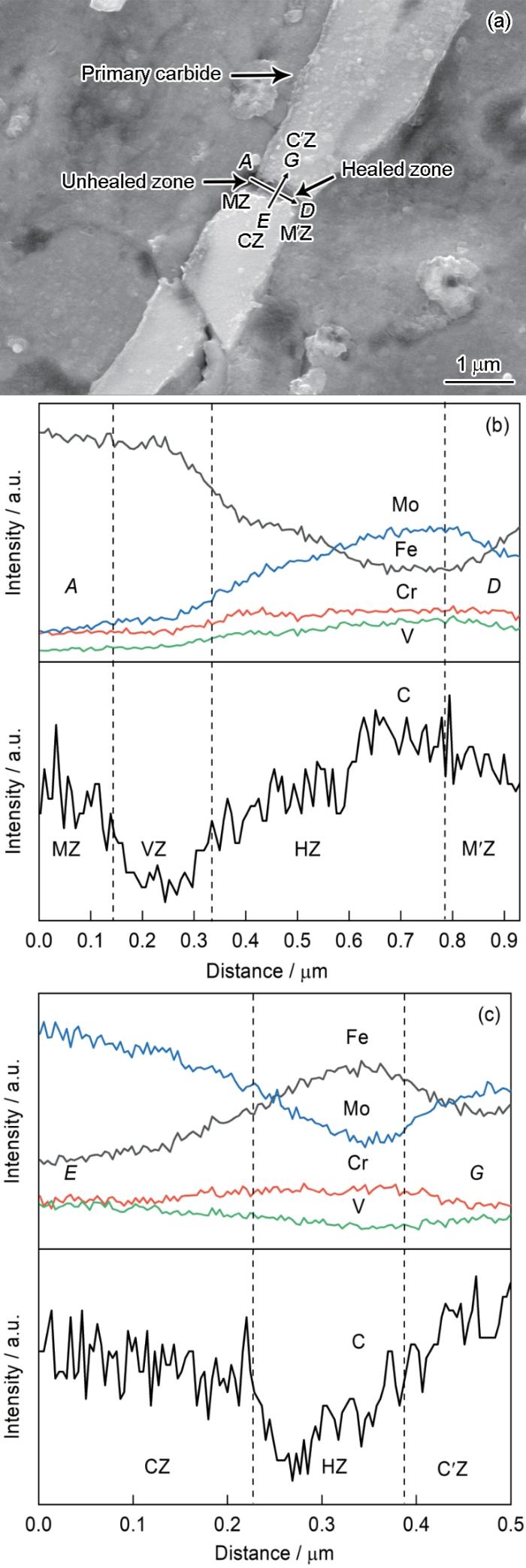
图11
热变形样品经850℃保温1 h后样品内部孔洞附近区域的SEM像及元素EDS线扫描分析
Fig.11
SEM image (a), and EDS line scanning analyses from line AD (b) and EG (c) of the voids of the thermal deformation sample soaking at 850oC for 1 h (MZ, M'Z—matrix zones; VZ—void zone; HZ—healed zone; CZ, C'Z—carbide zones)
针对图11的EDS线扫描结果及其他孔洞周围的点扫描结果,绘制出保温处理后孔洞周围碳化物区、愈合区、基体区3个区域的元素分布图,如图12a所示。可以看出,Fe元素主要集中于基体区,V与Mo元素则在碳化物区分布较多,受保温处理的影响,合金元素及C元素发生快速扩散,促使孔洞发生愈合,故愈合区集中了合金元素与C元素,对于孔洞与基体、碳化物3者交汇处,碳化物与基体中的原子均可向孔洞发生扩散迁移[39],且由于保温过程中碳化物析出和晶粒长大引起的体积膨胀也在一定程度填充孔洞,故孔洞的两侧先发生愈合,并逐步向中心扩展,同时孔洞发生球化。图10也展示出碳化物在高温保温过程中内部合金元素扩散而发生溶解球化,其中在γ-Fe中Cr元素的扩散能力要远高于Mo及V元素[40],因此从图12a可以看出,相对于其他元素来说Cr元素在愈合区大量富集,并高于基体和碳化物中的Cr含量。为了进一步分析保温对孔洞的愈合效果,取变形后的样品分别保温0、1、5和10 h来观察孔洞的愈合情况,不同温度保温后的孔洞平均面积的统计结果如图12b所示。可以看出,随保温时间的增加孔洞面积随之减少,且大尺寸孔洞数量也随之降低,保温处理可显著促进孔洞的愈合。
图12
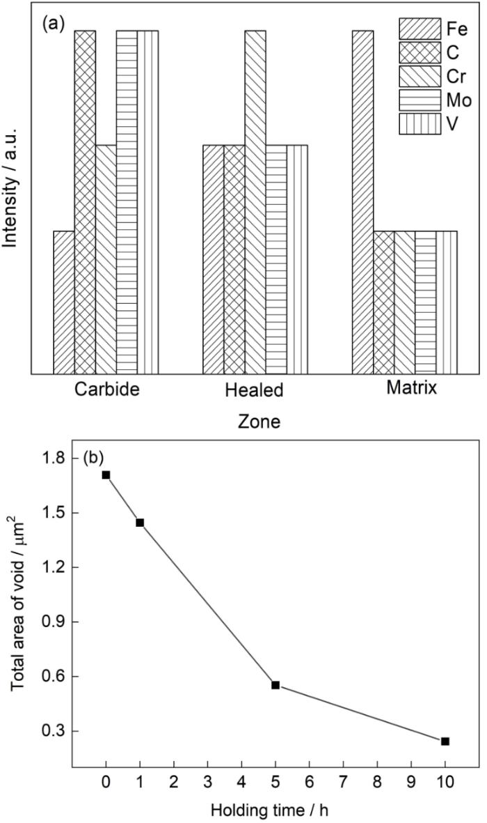
图12
保温样品内部不同区域元素分布图及不同温度保温后孔洞平均面积的统计结果
Fig.12
Trend diagram of element distribution in different regions (a) and statistical results of the average area of voids at different holding time of soaking sample (b)
3 结论
(1) M50轴承钢中存在大量呈网状分布的M2C和MC型一次碳化物,在后续热变形过程中,碳化物与基体由于硬度差异导致变形不协调,从而诱发孔洞产生。一部分孔洞由于基体与碳化物变形不协调而产生在碳化物与基体界面处,另一部分孔洞则在应变载荷的作用下产生于断裂破碎的碳化物中间。
(2) 不同的变形条件对孔洞产生的影响不同,在不同的变形量下(10%~50%),中等变形量(30%)时产生的孔洞体积分数最多,可达0.193%;在不同温度变形时(1000~1150℃),较低温度下(1000℃),产生的孔洞体积分数最多可达0.229%;而对于不同的应变速率(0.001~1 s-1),较高应变速率下(1 s-1),变形孔洞体积分数达到最大,为0.149%。
(3) 保温处理可促进孔洞发生愈合,在愈合区发现Cr元素的大量富集,愈合部位优先发生于孔洞与碳化物、基体的界面交汇处。
参考文献
Kinetics of vanadium carbonitride precipitation in steel: A computer model
[J].
Analysis of microporosity associated with insoluble carbides in VIM-VAR AISI M-50 steel
[J].
Effect of decreased hot-rolling reduction treatment on fracture toughness of low-alloy structural steels
[J].
Influence of sulfide inclusion on ductility and fracture behavior of resulfurized HY-80 steel
[J].
An in situ SEM study of void development around inclusions in steel during plastic deformation
[J].
Analysis of the deformation mechanism of void generation and development around inclusions inside the sheet during sheet rolling processes
[J].
Ductile failure by void nucleation, growth and coalescence
[J].
Simulation of the behaviour of voids in steel plates during hot rolling
[J].
Void initiation close to a macro-inclusion during single pass reductions in the hot rolling of steel slabs: A numerical study
[J].
Deformation behavior of inclusions in stainless steel strips during multi-pass cold rolling
[J].
Formation mechanism of voids around hard inclusion during hot rolling processes
[J].
To investigate the mechanism by which voids form around hard inclusions, the deformations of a plastic slab with hard and soft inclusions that form inside it during the hot rolling process have been simulated with a finite element method. By comparing plastic strain distributions, the relative displacements of contact surfaces, and the deformations between hard and soft inclusions have preceded analysis of the formation mechanism of these voids. The variations of strain measurements between the matrix and hard inclusions cause relative displacement of their contact surfaces. Therefore, voids occur at the front and rear of the hard inclusions. Trials on the slab deformations using a titanium ball instead of the soft inclusion inside the slab during the hot rolling process are conducted. The simulated shapes of the soft inclusions with different reductions mostly agree with the experimental results.
Deformation behavior of MnO13%-Al2O318%-SiO269% inclusion in different steels during hot rolling processes
[J].
Determination of the critical inclusion size with respect to void formation during hot working
[J].
Evolution of interfacial voids around a cylindrical inclusion
[J].
Evolution of voids close to an inclusion in hot deformation of metals
[J].
Formation of interfacial voids in composites with a weakly bonded viscoplastic matrix
[J].
Micro-mechanical modelling of strain induced porosity under generally compressive stress states
[J].
A study of pore closure and welding in hot rolling process
[J].
A study on central crack formation in cross wedge rolling
[J].
Effects of thermal deformation on refinement and uniformity of carbide in high temperature bearing steel
[J].
热变形对高温轴承钢中碳化物的均质化与细质化影响规律研究
[J].
Amelioration of surface cracking during hot rolling of AISI D2 tool steel
[J].
Voids healing and carbide refinement of cold rolled M50 bearing steel by electropulsing treatment
[J].The voids caused by the cold rolling (CR) quite deteriorates the final performance of M50 bearing steel. In this work, the effect of electropulsing treatment (EPT) on the voids has been investigated, finding that the nano-size voids around carbides have been extensively healed. Moreover, it is interesting to find that the Cr-rich carbides are partially dissolved and consequently refined by EPT, which could be attributed to the decreased thermodynamic dissolution barriers and accelerated kinetic diffusion of carbon atoms towards dislocation. These results inspire people to develop a novel strategy (CR + EPT) to fully take advantage of CR and tailor the carbides size in bearing steels.
Formation mechanism of MC and M2C primary carbides in as-cast M50 bearing steel
[J].
Transformation behavior of primary MC and M2C carbides in Cr4Mo4V steel
[J].
Control countermeasures of center porosity and shrinkage in 45 steel continuous casting bloom
[J].
45钢连铸大方坯中心疏松与缩孔控制
[J].
Computer simulation of shrinkage related defects in metal castings—A review
[J].
Formation mechanism and coupling prediction of microporosity and inverse segregation: A review
[J].Microporosity and inverse segregation are two common casting defects mainly caused by solidification shrinkage, which are detrimental to the mechanical properties of components, especially to the fatigue performance and ductility. Numerous efforts have been put into the investigation on microporosity and inverse segregation independently. However, few work has been done to establish a theoretical model for predicting the two defects simultaneously, whereas they often interact with each other and the formation of microporosity may exert a beneficial effect on inverse segregation. In this review, the coupling models for prediction of microporosity and inverse segregation were introduced. Firstly, the mechanisms and the predicting models for the two defects were summarized separately. Microporosity is a resultant of solidification shrinkage and gas segregation. Therefore, the porosity was previously categorized into two types: shrinkage porosity and gas porosity. More recent porosity models have combined the effect of pressure drop induced by feeding, the evolution of pores radius, the decrease of gases solubility in the liquid and the gas rejection at the solid/liquid interface, which provide rather good approximation to experimental results. As for inverse segregation, it is mainly caused by the suction of interdendritic liquid which is generally rich in solute. Therefore, determination of the feeding velocity is crucial for most inverse segregation models. Then, through the analysis of the underlying interaction between microporosity and interdendritic feeding flow, the coupling methods for prediction of the two defects were reviewed. Most of the models have added porosity into the continuity equation to amend the feeding velocity and utilized the “local solute redistribution equation” to get the solute concentration profiles. A new coupling model recently proposed by the present authors, based on analyses of the redistribution of gases element as well as the alloying element, is also in this route. The result shows that for Al-4.5%Cu (mass fraction) alloy solidified in a columnar dendrites structure, the predicted fraction of microporosity is a little smaller than that of Poirier's model, and the increase of initially dissolved hydrogen in the melt will decrease the solute enrichment in the interdendritic liquid. Microporosity seems to reduce the flow needed to compensate the solidification shrinkage, thus the solute segregation gets reduced. Finally, several suggestions were proposed, including the treatment of pore radius, eutectic shrinkage and gas porosity precipitated during eutectic reaction, etc.
微观孔洞和逆偏析缺陷的形成机理与耦合预测研究进展
[J].本文首先分别总结了微观孔洞和逆偏析2种凝固缺陷的形成机理及各自预测模型的发展,然后对二者的耦合预测模型发展做了概括总结,最后重点介绍了近期作者所建立的一个新的耦合预测模型。该模型首先利用气体元素在液-固-气三相中的分配规律,结合因液相在枝晶间补缩通道内流动受阻引起的局部压降,建立了一个新的微观孔洞预测模型;然后结合微观孔洞的析出对糊状区枝晶间补缩液流的影响规律,对经典的“局部溶质再分配方程”进行修正,得到一个新的逆偏析解析模型。针对以柱状枝晶方式定向凝固的Al-4.5%Cu (质量分数)合金的计算结果表明,凝固过程中微观孔洞的形成,会补偿糊状区中的凝固收缩,从而减少枝晶间的补缩液流,使糊状区枝晶间溶质富集程度减小,最终使逆偏析得到缓解。
High temperature behavior of isothermally compressed M50 steel
[J].
Effect of multi-direction forging on carbide evolution of M50 steel
[J].
多向锻造对M50钢一次碳化物破碎机制的影响
[J].
Deformation of non-metallic inclusions during steel rolling
[J].
Critical shapes and arrangements of carbides in high-speed tool steel
[J].
Breakdown behavior of eutectic carbide in high speed steel during hot compression
[J].
Spheroidizing kinetics of eutectic carbide in the twin roll-casting of M2 high-speed steel
[J].
A model for shrinkage of a spherical void in the center of a grain: Influence of lattice diffusion
[J].
An axisymmetric model of pore-grain boundary separation
[J].
Diffusive healing of intergranular fatigue microcracks in iron during annealing
[J].
In situ electron microscopy investigation of void healing in an Al-Mg-Er alloy at a low temperature
[J].
Geometric and chemical composition effects on healing kinetics of voids in Mg-bearing Al alloys
[J].
Discovery of inner crack recovery and its structure change in 20MnMo steel
[J].By physical modelling, the recovery phenomenon of inner crack in 20MnMo steel at high temperature was discovered, and its regular pattern was concluded.It was believed that the recovery process was mainly controlled by the diffusion and migration of metal atoms. The recovery process can be divided into two steps, void filling and grain growing. The filling materials consisted of many very fine grains with segregation of iron. There was a very clear boundary between the filling materials and matrix. The grain growing and composition homogenzing occurred simultaneously. Inner cracks and voids can be filled and taken away in a certain deformation. A certain holding time was necessary for grain growing and inner crack recovery entirely.Correspondent: HAN Jingtao, associate professor, Department of Metalworking, University of Scicnce and Technology Beijing, Beijing 100083
20MnMo钢内裂纹修复现象的发现及其金属组织的变化
[J].通过物理模拟研究,发现了20MnMo钢内裂纹在高温下可修复的现象,并总结了其初步规律,认为这种修复过程主要是由原子的扩散迁移所造成.内裂纹的修复可分为空洞填充和晶粒长大两个阶段。填充物初期由细小晶粒所组成,存在Fe的成分偏析,与基体的分界面清晰.随后的晶粒长大与成分均匀化同时进行.一定的塑性变形,可使内裂纹及空洞等被很好的填充和压合.为保证内裂纹的完全修复,需一定的保温时间,使晶粒充分长大.
