


由于双相钢的生产规模大、成本低、易于加工,在保持高强度的同时保持了良好的塑性和韧性[1],所以在汽车行业中被广泛使用[2]。双相钢通常具有类似复合材料的微观结构:在软的铁素体基体上分布着硬的第二相组织,如马氏体、亚稳奥氏体或贝氏体等。在变形过程中,软的铁素体基体容易发生变形使其具有好的塑性,硬的第二相又保证了强度的要求。材料韧性断裂的一个关键物理过程是孔洞的形核、生长和聚合,诸多研究者发现,在双相钢的铁素体-马氏体界面上观察到孔洞形核是通过相界面的分离或第二相在中高应变条件下断裂形成的[3,4],而在低应变条件下,孔洞可以在夹杂物的界面上较早形核[4]。大量的双相钢断裂行为研究表明,在这些双相钢中,夹杂物引起的损伤是一种重要的破坏机制[5~9],Al2O3和硫化物夹杂是重要的裂纹源[10],不过夹杂物孔洞的尺寸和形状对Lode参数不敏感[11],仅与应力三轴度相关[12]。此外,与夹杂物有关的孔洞形核具有尺寸效应:与小颗粒相比,孔洞形核更易在大颗粒夹杂物上出现[5,6],减少大颗粒夹杂物的数量可以作为提高双相钢强度和塑性的一个设计准则。钢的总塑性应变对孔洞的数量有较大的影响[13],研究孔洞在双相钢韧性断裂过程中的形核和长大行为,有助于更好地认识孔洞在裂纹的萌生和扩展中的作用,以评估材料在服役过程中的损伤演化,同时,也为设计新钢种和改进现有钢种提供新的思路。
通常,孔洞在夹杂物上形核通过空位聚集、颗粒与基体界面分离或颗粒断裂等机制实现。在高温和低应变速率下,以空位聚集成孔洞的形核机制较为常见,这种机制多与蠕变相关[14]。有研究[6,15]表明,当形成孔洞的界面能小于基体表面能的0.1%时,较易发生空位聚集诱导的孔洞形核现象。对于机械变形引起的孔洞形核,颗粒断裂和颗粒与基体界面的分离是2种相互竞争的机制。究竟哪种机制占主导地位,取决于颗粒与基体之间强度的差异[14]。一般来说,颗粒与基体强度差异较大时倾向于通过界面分离形成孔洞。此外,还有一些其他因素也会对这2种模式的竞争机制产生影响,例如颗粒的形状和应力的大小,这是由于球形颗粒和较大的内应力会促进界面分离,实现孔洞形核所致[5]。
孔洞的聚合是形成微裂纹的重要机制,它可以通过下述一种或多种机制的协同产生[20,21]:(1) 局部颈缩:孔洞长大到一定程度之后相邻孔洞之间的基体难以承受外加变形的载荷,因而产生局部化变形,最终导致相邻孔洞之间的基体局部断裂,孔洞在垂直于外部加载的方向上连接;(2) 局部剪切:与局部颈缩相似,这种模式也是由于局部塑性流变造成的,与(1)区别在于孔洞分布在与加载轴呈一定角度的方向上,特别是在45°最大剪切力下最易产生。此外,文献[5]中还使用过一些诸如“void sheeting”和“necklace coalescence”等词汇来描述孔洞沿剪切带和晶界的聚合现象,但是都认为,孔洞聚合基本上取决于孔洞本身的生长动力学和孔洞间距[22]。
式中,k = E* / E,E*和E分别是颗粒和基体的Young's模量;β是一个取决于k以及颗粒和基体Poisson比的系数;r是颗粒半径。
式中,a是主滑移系的累积应变,d是颗粒直径,l是位错环的长度,b是Burgers矢量模。从
1 实验方法
本工作所用铁素体-贝氏体双相钢的主要化学成分(质量分数,%)为:C 0.035,Si 0.30,Mn 1.51,P < 0.002,S < 0.001,Nb 0.046,V 0.051,Fe余量,C当量为0.30。热处理过程详见参考文献[30],热处理后钢中的贝氏体含量为10% (质量分数)。
铁素体-贝氏体双相钢通过线切割加工成棒状拉伸试样,长度为2.0 mm、直径为1.1 mm,中心制备半径为0.1 mm的圆形凹槽以提高应力三轴度。原位拉伸实验使用放置在Versa 520 XCT设备中最高载荷5 kN的Deben CT5000拉伸试验台进行拉伸测试,应变速率约为8 × 10⁻⁴ s-1。拉伸应力达到抗拉强度(UTS)之后,在不同工程应变(ε = 0.038、0.047、0.049、0.05、0.053)状态下和断裂后进行CT扫描,以监测应力达到UTS后不同应变状态下的孔洞生长情况。每次CT扫描前将负载减少10%并静置15 min,以减少扫描过程中图像的漂移。XCT实验使用110 kV下10 W的X射线源,在360°旋转的过程中,采用多模态关联成像方法共收集到1201张投影照片。每个照片曝光时间为75 s,使用4倍的物镜采集,并进行2 × 2的像素合并,得到有效空间分辨率约为2.04 μm。使用Reconstructor软件中的filtered back projection算法对实验收集到的1201个投影进行三维体积重构,并使用Avizo软件(ThermoFisher Scientific)进行可视化处理。在断裂后的样品上选取感兴趣的孔洞,在其上方约50 μm的位置上沿轴向切割并抛光,运用Gemini SEM 460扫描电镜(SEM)获取截面像,并与相应位置处的XCT切片图进行比较,以确认抛光后孔洞的次表层位置。接着使用Helios Xe+ PFIB[31]对体积为98 μm × 98 μm × 80 μm且包含预选孔洞的区域进行块体挖掘,使用30 kV、0.18 μA的束流进行连续切片EBSD成像[32]。EBSD实验参数为20 kV和22 nA,工作距离为10 mm,使用NordlysMax2系统和Aztec软件收集衍射花样,EBSD摄像头增益设定为0,曝光时间为10 ms,使用4 × 4像素合并,采样频率为100 Hz、采样步长为0.25 μm。在此参数设定下每个EBSD切片采样大约需要16 min。由于样品变形量较大,为提高EBSD衍射花样质量,采用高曝光时间和低采样频率。3D-EBSD体积重建使用Dream3D (dream3d.bluequartz.net)开源软件,为降低相邻切片的错配度,首先实现相邻切片中晶粒之间的最大重叠来进行相邻切片的对齐堆叠,接下来通过最小化每个切片中的像素点与其上下切片对应像素之间的取向差来进一步调整对齐。使用ParaView (paraview.org)开源软件对3D-EBSD进行可视化处理。
2 实验结果
2.1 孔洞的多尺度成像分析
图1a~e为不同应变时XCT数据的二维切片图,反映了达到UTS之后孔洞的形核、生长以及断裂过程。可以看出,在ε达到0.05后孔洞加速形核,在ε达到0.053时,多数孔洞发生聚合,导致立即断裂(图1f)。从样品中间的人字形裂缝(图1f中黄色虚线框)可以看出,裂纹源是由局部剪切引起孔洞聚合后,两侧区域发生剪切失效形成特有的杯锥状断口,并在加载方向大致45°位置处形成剪切唇(图1f中红色虚线框)。图1g和h为图1e中所指不同位置的横截面切片图。从图1g的横向切片图可以看出,大量的孔洞聚集在样品截面的左侧,这可能是由于左侧缺口稍深,变形不均匀,从而产生了更多的孔洞所致,图1h中的孔洞较少且分布很分散。图1i为双相钢单向拉伸的应力-应变曲线。图1a中所标定的2个孔洞从拉伸应力达到UTS后,裂纹开始形核,裂纹生长贯穿整个颈缩阶段,直到断裂,整个过程中没有与其他孔洞合并。这种方法适合孔洞生长的局部组织结构环境影响的研究。
图1

图1
拉伸应力达到极限抗拉强度(UTS)后在不同工程应变(ε)水平下和断裂后的XCT二维切片图和单向拉伸应力-应变曲线
Fig.1
2D slice images of time-lap CT scans at different strain (ε) levels post ultimate tensile strength (UTS) (a-h) and stress-strain curve (i) (The rate of void nucleation increases rapidly between nominal strain of 0.05 and 0.053, which quickly coalesced and led to fracture)
Color online
(a) ε = 0.038 (b) ε = 0.047 (c) ε = 0.049
(d) ε = 0.05 (e) ε = 0.053 (f) fracture
(g) slice at the fracture surface before fracture in Fig.1e (h) slice at the region of interest shown in Fig.1e
通过横截面直径(D)计算出2个孔洞位置的真实应变(εT),εT = ln (
图2
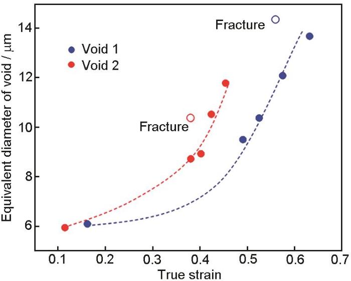
图2
图1a中2个孔洞的等效直径与样品相应截面上真实应变的关系
Fig.2
Equivalent diameters of two voids in Fig.1a as a function of true strain at the corresponding cross section of the sample (Each data point corresponds to a scan point marked in Fig.1i)
Color online
使用XCT、PFIB和EBSD技术详细研究了2个孔洞附近的显微组织,实验过程如图3所示。如图3a所示,通过XCT确定孔洞的空间坐标,在此基础上,对样品进行切割和抛光,使孔洞位于抛光表面下约50 μm处,以方便后续实验。使用PFIB对包含孔洞的区域整体挖掘(图3b)并进行连续切片EBSD扫描(图3c)。通过3D-EBSD扫描结果二维切片和三维统计的晶粒尺寸分布比较(图3d)可以看出,三维分析的晶粒尺寸更接近正态分布,三维真实晶粒尺寸比二维截面晶粒尺寸平均高出3倍。这是由于在二维截面上计算的晶粒尺寸只能反映晶粒尺寸分布的下限,而一个界面横跨截面上所有晶粒大圆的概率是极低的。图4a显示了图1a中标注的2个孔洞和周围晶粒的形态。可以看出,孔洞1位于晶界位置,而孔洞2完全被包裹在一个晶粒内,根据图4b所示孔洞生长的位错机制可以看出,孔洞2左右两侧的晶界限制了位错滑移,导致与孔洞1相比,孔洞2在水平方向的尺寸较小,故整体形貌较为狭长。
图3

图3
研究孔洞生长的多模态关联表征方法
Fig.3
Multimodal correlative approach to study void growth
Color online
(a) XCT morphology of the fractured sample, voids coloured in red
(b) bulk cut out by PFIB at the corresponding location indicated by circle in Fig.3a
(c) serial sectioning 3D-EBSD reconstruction (~98 μm × 98 μm × 80 μm) of the cutted bulk shown in Fig.3b
(d) comparisons between 2D and 3D grain size distributions
图4
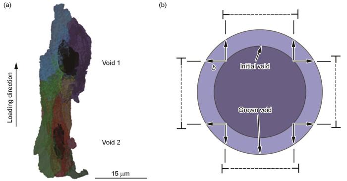
图4
图1a所示的2个孔洞及其周围晶粒的XCT三维视图,以及孔洞生长的位错环机制示意图
Fig.4
High resolution XCT morphology of the two voids shown in Fig.1a together with the grains surrounding the two voids (a), illustration demonstrating void expansion caused by glide of dislocation loops (b—Burgers vector module) (b)
Color online
2.2 孔洞形核点的微观结构
图5
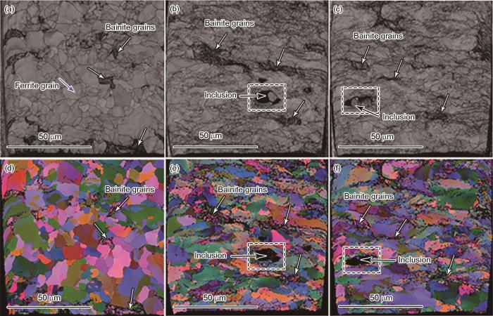
图5
低应变区和包含孔洞1和孔洞2的中间截面高应变区域的EBSD带对比图和Euler角着色像
Fig.5
EBSD band contrast maps (a-c) and EBSD maps colored with Euler angles (d-f) in low strained region showing the un-deformed images (a, d) and high strained regions featuring the mid cross section of void 1 (b, e) and void 2 (c, f)
Color online
从3D-EBSD像(图3c)可以发现大量低于XCT分辨率的小孔洞。可将这些孔洞大致分为3组:与贝氏体相关的孔洞(位于相界或内部,包括在贝氏体相内的夹杂物周围出现的形核孔洞)、铁素体中非夹杂物孔洞以及铁素体内夹杂物周围的孔洞,统计结果显示在图6中。可以看出,铁素体中由夹杂物形核的孔洞尺寸大于在贝氏体中形核的孔洞尺寸。需要说明的是,大多数与贝氏体相关的孔洞周围没有观察到夹杂物,有可能是夹杂物太小而无法分辨或是夹杂物在PFIB切片过程中脱落。将铁素体中夹杂物尺寸和与之对应的孔洞尺寸进行对比,显示2者呈正相关关系,如图7所示。但是对孔洞位置的真实应变进行分析发现,真实应变与孔洞尺寸的相关性较弱,如图7中所示的尺寸在1.5~2 µm之间的夹杂物产生的孔洞相互之间真实应变差异巨大,但是孔洞尺寸却十分接近,这表明孔洞的尺寸不仅由夹杂物尺寸决定,还与孔洞本身的生长机制有关。
图6
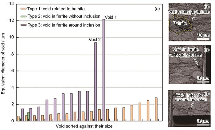
图6
PFIB-SEM样本(体积约98 μm × 98 μm × 80 μm)中孔洞的尺寸和类型,以及每种类型孔洞形貌的SEM像
Fig.6
Sizes and types of void in the PFIB-SEM sampled volume (~98 µm × 98 µm × 80 µm) (a) and SEM images of voids type 1 (b), type 2 (c), and type 3 (d)
Color online
图7

2.3 孔洞的生长机制
2.3.1 孔洞附近的塑性变形
由于位错环或反平行位错偶的形核和滑移是塑性诱发孔洞增长的重要机制,因此有必要研究铁素体晶粒周围的变形能力与孔洞尺寸差异的关系。bcc晶体具有多个密排面,主要滑移系有3种:{1
图8

图8
孔洞周围的平均几何必需位错(GND)密度与夹杂物尺寸的关系
Fig.8
Average geometrically necessary dislocation (GND) density in the vicinity of voids as a function of associated inclusion size
2.3.2 孔洞的各向异性生长
式中,SFi 是第i个像素的Schmid因子,Di 是第i个像素所在晶粒的等效直径。在此计算中,晶粒中每个像素的Schmid因子由相应晶粒的尺寸加权,因此较小晶粒中的Schmid因子被加权降低,而较大晶粒中的Schmid因子被加权提高。图9a3~a6分别给出了孔洞的EBSD带对比图、Schmid因子分布图、加权Schmid因子分布图和GND密度分布图。图9a1为对图9a3中孔洞两侧黄色虚线框区域统计平均GND密度,图9a2为这2个区域的平均Schmid因子和平均加权Schmid因子。GND密度分布图表明孔洞一侧优先生长,其累积滑移量比另一侧大,Schmid因子分布图也表明孔洞优先生长一侧的晶粒具有更高的变形能力。加权Schmid因子分布图揭示了一些传统Schmid因子图无法显示的有趣的特征,例如图9a5中显示的大孔洞右侧的生长更倾向于向右下方的晶粒内延伸(晶粒4),这个晶粒拥有更高的加权Schmid因子,相比之下,孔洞右上方的晶粒尺寸很小,所以即便其具有更高的Schmid因子,但由于小晶粒尺寸Schmid因子被加权降低,所以晶粒不易塑性流动。
图9

图9
孔洞1和孔洞2的GND密度和Schmid因子,孔洞的EBSD带对比图、Schmid因子分布图、加权Schmid因子分布图和GND密度分布图
Fig.9
GND densities (ρGND) (a1, b1) and Schmid factors (a2, b2) of the left and right parts around the voids in Figs.9a3 and b3; and EBSD band contrast maps (a3, b3), Schmid factor distributions (a4, b4), weighted Schmid factor distributions (a5, b5), and GND density distributions (a6, b6) of void 1 (a1-a6) and void 2 (b1-b6)
Color online
3 分析讨论
3.1 孔洞的形核和生长
本工作所研究的铁素体-贝氏体双相钢样本中所有夹杂物颗粒都呈球状且没有发现夹杂物断裂现象。样品中大尺寸夹杂物主要是Al2O3夹杂,同时在其边缘伴生有MnS形成复合夹杂物。其断裂强度比铁素体基体高3倍多,因此在这种材料中铁素体/夹杂物的界面分离是变形过程孔洞形核的主要机制[8]。
综上所述,夹杂物的尺寸不仅影响孔洞形核的难易程度,也能够通过局部位错塞积影响孔洞的尺寸。这2种机制协同作用造成大夹杂物引起的孔洞较大、小夹杂物引起的孔洞较小的实验现象。决定孔洞快速生长和慢速生长的夹杂物临界尺寸可以利用Goods和Brown[6]提出的模型进行估算:将α = 0.3、b = 0.248 nm (α-Fe)代入
表1 不同钢种依据式(6)的夹杂物临界尺寸估算
Table 1
| Material | μ / GPa | σy / MPa | rc / µm | |
|---|---|---|---|---|
| Low-carbon steel | 80 | 295 | 200 | 2.06 |
| Ferrite in ferrite-bainite dual-phase steel[45] | 72 | 370 | 106 | 2.51 |
| Bainite in ferrite-bainite dual-phase steel[45] | 76 | 830 | 258 | 0.51 |
| Ferrite in 600 MPa ferrite-martensite dual-phase steel[46] | 78 | 313 | 160 | 2.30 |
| Martensite in 600 MPa ferrite-martensite dual-phase steel[46] | 79 | 1014 | 167 | 0.32 |
| Ferrite in 1000 MPa ferrite-martensite dual-phase steel[46] | 78 | 443 | 141 | 1.85 |
| Martensite in 1000 MPa ferrite-martensite dual-phase steel[46] | 79 | 813 | 280 | 0.52 |
| Ferrite in ferrite-martensite dual-phase steel[47] | 79 | 260 | 159 | 2.86 |
| Martensite in ferrite-martensite dual-phase steel[47] | 79 | 1000 | 460 | 0.26 |
| Ferrite in ferrite-martensite dual-phase steel[48] | 77 | 430 | 117 | 2.24 |
| Martensite in ferrite-martensite dual-phase steel[48] | 77 | 1450 | 431 | 0.18 |
Table 2
| Material | Matrix | Inclusion type | Critical size of inclusion / µm | Ref. |
|---|---|---|---|---|
| Steel | Ferrite | Silicate, TiN | 2-4 | [49] |
| A508 steel | Bainite | MnS | 17 × 10 × 3 | [50] |
| SAE52100 | Martensite | Ca-Al-O, Ti(N, C) | 21 | [51] |
| 600 MPa high-strength steel | Martensite | Inclusion | 2 | [52] |
| Ferrite-martensite dual-phase steel | Ferrite + martensite | Inclusion | Correlated with martensite phase size | [48] |
| High-strength steel | Martensite | Al2O3 | 16 | [53] |
| High-strength steel | Martensite | TiN | 11 | [53] |
| Bearing steel | Martensite | Mg-Al-O | 8.5 | [54] |
| Bearing steel | Martensite | Calcium aluminate | 13.5 | [54] |
| Pipeline steel | Ferrite + pearlite | MnS | 2.52-2.6 | [55] |
| SLM IN718 | Ni suppralloy | Void | 20 | [56] |
由表1可大致确定铁素体中夹杂物周围孔洞形核的临界尺寸在1.85~2.86 µm之间,与本工作估算值吻合较好;且从表1可以看出,受贝氏体和马氏体较高的弹性模量和加工硬化率影响,其内弹性应力在加载过程中累积速率高于基体,因此其内部夹杂物的临界尺寸相对较低,贝氏体临界尺寸约为0.51 µm,马氏体临界尺寸在0.18~0.52 µm之间。本工作临界尺寸与表2[48~56]中个别文献报道吻合,但大部分文献报道的临界尺寸整体较高,这可能与具体分析方法的空间分辨率有关。除此之外,由于靠近孔洞位置的EBSD解析率降低且材料整体变形严重,图8中呈现的位错分析标准误差较大,因此夹杂物尺寸与局部位错密度的关系模型难以建立。需要使用变形程度较低的材料以及一些先进的衍射花样标定方法来进行改进,如具有更好鲁棒性和更高分辨率的字典算法[57,58]。
3.2 孔洞的择优生长及晶粒尺寸的影响
在大孔洞的延伸过程中可能存在如图9所示的择优生长现象,即孔洞并非以夹杂物为中心向外均匀扩展,这种生长模式在文献[59,60]中也有报道。仔细研究孔洞周围显微组织可以发现,孔洞的择优生长不是随机的,而是由周围晶粒的微织构控制的,正如图9a4、a6和图9b4、b6 所示孔洞择优生长一侧的Schmid因子和GND密度都要高出另外一侧。图9a6所示孔洞中右侧晶粒1~3都表现出较高的Schmid因子,但由于它们的晶粒尺寸较小,因此不利于孔洞生长。晶粒4具有更大的尺寸和同样高的Schmid因子,因此孔洞更倾向于向晶粒4一侧生长。从图9a5中同样可以看出,大孔洞与右边的小孔洞进行连接合并十分困难,这是因为连接孔洞的晶粒1、2和3由于较低的加权Schmid因子无法提供足够的塑性流动来激发合并机制(局部缩颈或局部剪切[5])。由此可以认为,在本工作铁素体-贝氏体双相钢内只包含小颗粒的情况下,由于孔洞本身生长会受到制约,通过孔洞生长导致塑性断裂的可能性较低,这种情况下塑性断裂主要取决于孔洞的间距和分离孔洞的基体的变形能力。对于孔洞间织构上较软的基体(高SFi*),塑性流变可以较快缩减孔隙间距,导致孔洞在相对较低的应变下发生连接合并,形成微裂缝并最终导致断裂。
4 结论
(1) 使用多模态关联的表征分析方法研究了铁素体-贝氏体双相钢韧性断裂过程中孔洞的生长行为及孔洞周围局部微观结构对孔洞生长的影响。受限于XCT实验的空间分辨率,实验过程只观察到了铁素体中2 µm以上夹杂物导致孔洞形核的现象,但是通过关联性3D-EBSD表征,发现贝氏体中尺寸小于2 µm的夹杂物也引发了孔洞形核。与贝氏体相比,铁素体相中的夹杂物会导致更大的孔洞,这主要与铁素体相的变形抗性较弱或者铁素体中夹杂物诱发孔洞形核所需的应变整体较低有关。
(2) 孔洞的生长受夹杂物尺寸效应影响显著,较小的夹杂物会引起局部高位错密度包壳阻碍位错滑移,从而限制孔洞的生长。通过解析理论模型,根据所研究材料的性质,计算出在铁素体相中夹杂物形核的临界尺寸在1.85~2.86 µm之间,低于这个临界尺寸的夹杂物,孔洞周围由于受到强变形梯度塑性的影响生长缓慢,高于这个临界尺寸的夹杂物则可导致孔洞的快速生长从而显著降低塑性与断裂韧性。
(3) 单向拉伸变形过程中,孔洞主要沿着加载方向生长,但孔洞周围晶粒的微观织构会改变其生长方向,表现出各向异性。孔洞的复杂形状可以用Schmid因子和晶粒尺寸相结合的加权Schmid因子进行预测。孔洞连接合并的难易程度会受到分隔孔洞之间基体材料的晶粒尺寸和织构的影响。
(4) 3D-EBSD晶粒尺寸表征结果显示,真实三维晶粒尺寸计算结果是二维表面计算结果的3倍左右,因此需谨慎对待二维表面晶粒度的测量结果。
参考文献
The influence of microstructure and composition on the plastic behaviour of dual-phase steels
[J].
An overview of dual-phase steels: Advances in microstructure-oriented processing and micromechanically guided design
[J].
Mesoscale simulation of the early evolution of ductile fracture in dual-phase steels
[J].
Damage micromechanisms in dual-phase steel investigated with combined phase- and absorption-contrast tomography
[J].
Failure of metals I: Brittle and ductile fracture
[J].
Overview No. 1: The nucleation of cavities by plastic deformation
[J].
On the competition between particle fracture and particle decohesion in metal matrix composites
[J].
Experimental characterization and numerical modeling of micromechanical damage under different stress states
[J].
Anisotropic ductile fracture: Part I: Experiments
[J].
Fracture evolution in ferrite/martensite dual-phase flange steel
[J].
Simulation of the influence of Lode parameter on ductile fracture using an ellipsoidal void model
[J].
Ductile fracture of high strength steels with morphological anisotropy, Part I: Characterization, testing, and void nucleation law
[J].
On the effect of strain and triaxiality on void evolution in a heterogeneous microstructure—A statistical and single void study of damage in DP800 steel
[J].
Void growth by dislocation emission
[J].
Note on vacancy condensation on particles
[J].
Work hardening of dispersion-hardened crystals
[J].
Shear impossibility: Comments on “Void growth by dislocation emission” and “Void growth in metals: Atomistic calculations”
[J].
Molecular-dynamics study of the mechanism and kinetics of void growth in ductile metallic thin films
[J].
Discrete dislocation dynamics analysis of the effect of lattice orientation on void growth in single crystals
[J].
A new model for void coalescence by internal necking
[J].
A micromechanical model for predicting the strain increment required to bring a damaged material element from the onset of void coalescence up to final fracture is developed based on simple kinematics arguments. This strain increment controls the unloading slope and the energy dissipated during the final step of material failure. Proper prediction of the final drop of the load carrying capacity is an important ingredient of any ductile fracture model, especially at high stress triaxiality. The model has been motivated and verified by comparison to a large set of finite element void cell calculations.
Visualization by X-ray tomography of void growth and coalescence leading to fracture in model materials
[J].
Experimental and numerical comparison of void growth models and void coalescence criteria for the prediction of ductile fracture in copper bars
[J].
Cavity formation at the interface of a spherical inclusion in a plastically deformed matrix
[J].
Continuum theory of ductile rupture by void nucleation and growth: Part I—Yield criteria and flow rules for porous ductile media
[J].Widely used constitutive laws for engineering materials assume plastic incompressibility, and no effect on yield of the hydrostatic component of stress. However, void nucleation and growth (and thus bulk dilatancy) are commonly observed is some processes which are characterized by large local plastic flow, such as ductile fracture. The purpose of this work is to develop approximate yield criteria and flow rules for porous (dilatant) ductile materials, showing the role of hydrostatic stress in plastic yield and void growth. Other elements of a constitutive theory for porous ductile materials, such as void nucleation, plastic flow and hardening behavior, and a criterion for ductile fracture will be discussed in Part II of this series. The yield criteria are approximated through an upper bound approach. Simplified physical models for ductile porous materials (aggregates of voids and ductile matrix) are employed, with the matrix material idealized as rigid-perfectly plastic and obeying the von Mises yield criterion. Velocity fields are developed for the matrix which conform to the macroscopic flow behavior of the bulk material. Using a distribution of macroscopic flow fields and working through a dissipation integral, upper bounds to the macroscopic stress fields required for yield are calculated. Their locus in stress space forms the yield locus. It is shown that normality holds for this yield locus, so a flow rule results. Approximate functional forms for the yield loci are developed.
Influence of voids on shear band instabilities under plane strain conditions
[J].
Analysis of the cup-cone fracture in a round tensile bar
[J].
Correlative tomography
[J].Increasingly researchers are looking to bring together perspectives across multiple scales, or to combine insights from different techniques, for the same region of interest. To this end, correlative microscopy has already yielded substantial new insights in two dimensions (2D). Here we develop correlative tomography where the correlative task is somewhat more challenging because the volume of interest is typically hidden beneath the sample surface. We have threaded together x-ray computed tomography, serial section FIB-SEM tomography, electron backscatter diffraction and finally TEM elemental analysis all for the same 3D region. This has allowed observation of the competition between pitting corrosion and intergranular corrosion at multiple scales revealing the structural hierarchy, crystallography and chemistry of veiled corrosion pits in stainless steel. With automated correlative workflows and co-visualization of the multi-scale or multi-modal datasets the technique promises to provide insights across biological, geological and materials science that are impossible using either individual or multiple uncorrelated techniques.
Multiscale correlative tomography: An investigation of creep cavitation in 316 stainless steel
[J].Creep cavitation in an ex-service nuclear steam header Type 316 stainless steel sample is investigated through a multiscale tomography workflow spanning eight orders of magnitude, combining X-ray computed tomography (CT), plasma focused ion beam (FIB) scanning electron microscope (SEM) imaging and scanning transmission electron microscope (STEM) tomography. Guided by microscale X-ray CT, nanoscale X-ray CT is used to investigate the size and morphology of cavities at a triple point of grain boundaries. In order to understand the factors affecting the extent of cavitation, the orientation and crystallographic misorientation of each boundary is characterised using electron backscatter diffraction (EBSD). Additionally, in order to better understand boundary phase growth, the chemistry of a single boundary and its associated secondary phase precipitates is probed through STEM energy dispersive X-ray (EDX) tomography. The difference in cavitation of the three grain boundaries investigated suggests that the orientation of grain boundaries with respect to the direction of principal stress is important in the promotion of cavity formation.
A multi-scale correlative investigation of ductile fracture
[J].
Microscopic deformation and strain hardening analysis of ferrite-bainite dual-phase steels using micro-grid method
[J].
Large volume serial section tomography by Xe plasma FIB dual beam microscopy
[J].Ga(+) Focused Ion Beam-Scanning Electron Microscopes (FIB-SEM) have revolutionised the level of microstructural information that can be recovered in 3D by block face serial section tomography (SST), as well as enabling the site-specific removal of smaller regions for subsequent transmission electron microscope (TEM) examination. However, Ga(+) FIB material removal rates limit the volumes and depths that can be probed to dimensions in the tens of microns range. Emerging Xe(+) Plasma Focused Ion Beam-Scanning Electron Microscope (PFIB-SEM) systems promise faster removal rates. Here we examine the potential of the method for large volume serial section tomography as applied to bainitic steel and WC-Co hard metals. Our studies demonstrate that with careful control of milling parameters precise automated serial sectioning can be achieved with low levels of milling artefacts at removal rates some 60× faster. Volumes that are hundreds of microns in dimension have been collected using fully automated SST routines in feasible timescales (<24h) showing good grain orientation contrast and capturing microstructural features at the tens of nanometres to the tens of microns scale. Accompanying electron back scattered diffraction (EBSD) maps show high indexing rates suggesting low levels of surface damage. Further, under high current Ga(+) FIB milling WC-Co is prone to amorphisation of WC surface layers and phase transformation of the Co phase, neither of which have been observed at PFIB currents as high as 60nA at 30kV. Xe(+) PFIB dual beam microscopes promise to radically extend our capability for 3D tomography, 3D EDX, 3D EBSD as well as correlative tomography. Copyright © 2015 The Authors. Published by Elsevier B.V. All rights reserved.
Xe+ plasma FIB: 3D microstructures from nanometers to hundreds of micrometers
[J].
Possible slip systems in body centered cubic iron
[J].
Slip planes in bcc transition metals
[J].
Some geometrical relations in dislocated crystals
[J].
Resolving the geometrically necessary dislocation content by conventional electron backscattering diffraction
[J].
High-resolution elastic strain measurement from electron backscatter diffraction patterns: New levels of sensitivity
[J].In this paper, we demonstrate that the shift between similar features in two electron backscatter diffraction (EBSD) patterns can be measured using cross-correlation based methods to +/- 0.05 pixels. For a scintillator screen positioned to capture the usual large solid angle employed in EBSD orientation mapping this shift corresponds to only approximately 8.5 x 10(-5)rad at the pattern centre. For wide-angled EBSD patterns, the variation in the entire strain and rotation tensor can be determined from single patterns. Repeated measurements of small rotations applied to a single-crystal sample, determined using the shifts at four widely separated parts of the EBSD patterns, showed a standard deviation of 1.3 x 10(-4) averaged over components of the displacement gradient tensor. Variations in strains and rotations were measured across the interface in a cross-sectioned Si1-x Gex epilayer on a Si substrate. Expansion of the epilayer close to the section surface is accommodated by tensile strains and lattice curvature that extend a considerable distance into the substrate. Smaller and more localised shear strains are observed close to the substrate-layer interface. EBSD provides an impressive and unique combination of high strain sensitivity, high spatial resolution and ease of use.
The effect of crystal orientation on the indentation response of commercially pure titanium: Experiments and simulations
[J].
Stress fields and geometrically necessary dislocation density distributions near the head of a blocked slip band
[J].
Dislocation density distribution at slip band-grain boundary intersections
[J].
The work-hardening of copper-silica V. Equilibrium plastic relaxation by secondary dislocations
[J].
Void growth in metals: Atomistic calculations
[J].
The type of dislocation interaction as the factor determining work hardening
[J].
On the nucleation and growth of twin in commercial purity titanium: In situ investigation of the local stress field and dislocation density distribution
[J].
Effect of bainite morphology on deformation compatibility of mesostructure in ferrite/bainite dual-phase steel: Mesostructure-based finite element analysis
[J].
On strain partitioning and micro-damage behavior of dual-phase steels
[J].
Computational modeling of dual-phase steels based on representative three-dimensional microstructures obtained from EBSD data
[J].
Microstructure-based modeling of the effect of inclusion on the bendability of advanced high strength dual-phase steels
[J].Advanced high strength dual-phase steels are one of the most widely sought-after structural materials for automotive applications. These high strength steels, however, are prone to fracture under bending-dominated manufacturing processes. Experimental observations suggest that the bendability of these steels is sensitive to the presence of subsurface non-metallic inclusions and the inclusions exhibit a rather discrete size effect on the bendability of these steels. Following this, we have carried out a series of microstructure-based finite element calculations of ductile fracture in an advanced high strength dual-phase steel under bending. In the calculations, both the dual-phase microstructure and inclusion are discretely modeled. To gain additional insight, we have also analyzed the effect of an inclusion on the bendability of a single-phase material. In line with the experimental observations, strong inclusion size effect on the bendability of the dual-phase steel naturally emerge in the calculations. Furthermore, supervised machine learning is used to quantify the effects of the multivariable input space associated with the dual-phase microstructure and inclusion on the bendability of the steel. The results of the supervised machine learning are then used to identify the contributions of individual features and isolate critical features that control the bendability of dual-phase steels.
Determination of the critical inclusion size with respect to void formation during hot working
[J].
Cavity nucleation, growth and stress field in elastic-plastic medium
[J].
弹塑性材料中孔洞成核、发展及应力场
[J].
Inclusion size distribution and endurance limit of a hard steel
[J].
Effects of inclusion size and acicular ferrite on cold cracking for high-strength steel welds of YS 600 MPa grade
[J].
Effects of inclusion types on the high-cycle fatigue properties of high-strength steel
[J].
Quantitative analysis of inclusion engineering on the fatigue property improvement of bearing steel
[J].The fatigue property is significantly affected by the inner inclusions in steel. Due to the inhomogeneity of inclusion distribution in the micro-scale, it is not straightforward to quantify the effect of inclusions on fatigue behavior. Various investigations have been performed to correlate the inclusion characteristics, such as inclusion fraction, size, and composition, with fatigue life. However, these studies are generally based on vast types of steels and even for a similar steel grade, the alloy concept and microstructure information can still be of non-negligible difference. For a quantitative analysis of the fatigue life improvement with respect to the inclusion engineering, a systematic and carefully designed study is still needed to explore the engineering dimensions of inclusions. Therefore, in this study, three types of bearing steels with inclusions of the same types, but different sizes and amounts, were produced with 50 kg hot state experiments. The following forging and heat treatment procedures were kept consistent to ensure that the only controlled variable is inclusion. The fatigue properties were compared and the inclusions that triggered the fatigue cracks were analyzed to deduce the critical sizes of inclusions in terms of fatigue failure. The results show that the critical sizes of different inclusion types vary in bearing steels. The critical size of the spinel is 8.5 μm and the critical size of the calcium aluminate is 13.5 μm under the fatigue stress of 1200 MPa. In addition, with the increase of the cleanliness of bearing steels, the improvement of fatigue properties will reach saturation. Under this condition, further increasing of the cleanliness of the bearing steel will not contribute to the improvement of fatigue property for the investigated alloy and process design.
Comparative study of non-metallic inclusions on the critical size for HIC initiation and its influence on hydrogen trapping
[J].
The role of defects and critical pore size analysis in the fatigue response of additively manufactured IN718 via crystal plasticity
[J].
A dictionary approach to electron backscatter diffraction indexing
[J].We propose a framework for indexing of grain and subgrain structures in electron backscatter diffraction patterns of polycrystalline materials. We discretize the domain of a dynamical forward model onto a dense grid of orientations, producing a dictionary of patterns. For each measured pattern, we identify the most similar patterns in the dictionary, and identify boundaries, detect anomalies, and index crystal orientations. The statistical distribution of these closest matches is used in an unsupervised binary decision tree (DT) classifier to identify grain boundaries and anomalous regions. The DT classifies a pattern as an anomaly if it has an abnormally low similarity to any pattern in the dictionary. It classifies a pixel as being near a grain boundary if the highly ranked patterns in the dictionary differ significantly over the pixel's neighborhood. Indexing is accomplished by computing the mean orientation of the closest matches to each pattern. The mean orientation is estimated using a maximum likelihood approach that models the orientation distribution as a mixture of Von Mises-Fisher distributions over the quaternionic three sphere. The proposed dictionary matching approach permits segmentation, anomaly detection, and indexing to be performed in a unified manner with the additional benefit of uncertainty quantification.
High resolution low kV EBSD of heavily deformed and nanocrystalline aluminium by dictionary-based indexing
[J].We demonstrate the capability of a novel Electron Backscatter Diffraction (EBSD) dictionary indexing (DI) approach by means of orientation mapping of a highly deformed graded microstructure in a shot peened Aluminium 7075-T651 alloy. A low microscope accelerating voltage was used to extract, for the first time from a bulk sample, statistically significant orientation information from a region close to a shot crater, showing both recrystallized nano-grains and heavily deformed grains. We show that the robust nature of the DI method allows for faster acquisition of lower quality patterns, limited only by the camera hardware, compared to the acquisition speed and pattern quality required for the conventional Hough indexing (HI) approach. The proposed method paves the way for the quantitative and accurate EBSD characterization of heavily deformed microstructures at a sub-micrometer length scale in cases where the current indexing techniques largely fail.
The stress at which dislocations are generated at a particle-matrix interface
[J].
