


随着先进航空发动机不断朝着高推重比、高涡轮前温度的方向发展,发动机对材料性能的要求越来越高。对于涡轮盘用镍基高温合金而言,相应的表现之一是合金化程度的提高,特别是γ'相形成元素,如Al和Ti含量的提高。这导致传统的涡轮盘成型方法,如铸锻成形方法,遇到了严重的宏观偏析和高加工流变应力等问题[1]。为了解决这些问题,从20世纪60年代起,粉末冶金加工被逐渐应用到镍基高温合金涡轮盘的加工上。但是粉末冶金工艺过程特点使得非金属夹杂物(non-metallic inclusions,NMIs)不可避免地引入到材料中[2],在疲劳载荷下,这些非金属夹杂物往往成为诱发“致命裂纹”(fatal crack)的裂纹源[3~6]。这些致裂非金属夹杂物尺寸在几十到200 μm之间[7,8],裂纹从这些夹杂物萌生后,随即进入“小裂纹”[9,10]扩展阶段。相关研究表明,René104[11]、IN100[12]、RR1000[13,14]、Udimet 720Li[13]和FGH4096[15]等合金的微小裂纹扩展过程均包含小裂纹扩展阶段。在该阶段,裂纹可以在长裂纹扩展门槛值(ΔKth)以下发生扩展,且在相同的应力强度因子范围(ΔK)下,小裂纹具有较长裂纹更高的裂纹扩展速率[10]。这表明,在小裂纹扩展阶段内无法沿袭对长裂纹扩展行为的认识,沿用长裂纹扩展速率模型将导致裂纹扩展寿命的非保守估计[9]。因此小裂纹扩展行为研究对于准确认识粉末冶金高温合金的裂纹扩展行为,建立小裂纹扩展速率模型与疲劳寿命预测模型都具有十分重要的意义。
一般认为小裂纹在扩展早期处于裂纹扩展第一阶段单滑移期(Stage Ia)和多滑移期(Stage Ib)[16],该阶段内裂纹沿着1个或者交替沿2个滑移面进行扩展直至进入裂纹扩展第二阶段(Stage II)。在Stage II内,裂纹开始沿垂直于最大主应力方向扩展。不同于长裂纹的裂纹扩展速率,包含粉末冶金高温合金在内,铝合金[17,18]、镁合金[19,20]、钛合金[20,21]、钢[23,24]等金属材料的小裂纹扩展速率往往并不随着ΔK的增加而单调增加,而是会经历多个速率先下降而后加速扩展的过程[17,19],并且小裂纹扩展速率开始下降的位置往往在晶界处[25]。一般认为[20]这个现象是由裂纹与晶界的交互作用导致的,晶界是阻碍小裂纹扩展的主要微观组织特征。但是裂纹扩展路径上并非所有的晶界都会对应着裂纹速率下降的位置,晶界能否阻碍裂纹扩展的主要因素有晶界自身的性质[26]、晶界两侧晶粒的相对取向[27~29]或晶界两侧裂纹面的空间取向关系[30,31]。
目前,关于小裂纹扩展行为的研究还使用长裂纹扩展的基本概念与方法,未能充分考虑到小裂纹的三维裂纹属性以及小裂纹扩展的物理基础。此外,小裂纹的研究多使用轻合金与钢铁材料,针对镍基粉末高温合金的小裂纹研究较少,因此本工作以镍基粉末高温合金FGH4096为研究对象,进行小裂纹扩展实验,重点从小裂纹的三维裂纹属性与扩展的物理基础出发,分析FGH4096中小裂纹的扩展行为。
1 实验方法
实验材料为镍基粉末高温合金FGH4096,其化学成分(质量分数,%)为:C 0.02~0.05,Cr 15.5~16.5,Co 12.5~13.5,Al 2.0~2.4,Ti 3.5~3.9,Mo 3.8~4.2,W 3.8~4.2,Nb 0.6~1.0,Zr 0.025~0.05,B 0.06~0.15,Fe ≤ 0.5,Ni余量。实验样品的热处理制度为:1140~1150℃、2 h、油冷 + 760℃、8 h、空冷,它在室温下的屈服强度和抗拉强度分别为1080~1210和1520~1600 MPa。
实验采用的试样为具有矩形横截面平行段的棒状试样。采用200号至2500号水砂纸对试样的平行段进行打磨后,再电解抛光至镜面。抛光液为:HClO4 (质量分数,70%)∶C6H14O2∶C2H6O=10∶35∶55 (体积比)。抛光电流1.2 A,温度-30℃,时间20 min。抛光完成后,进行金相腐蚀,腐蚀液组成为:5 g CuCl2 + 100 mL HCl + 100 mL C2H6O,腐蚀时间120 s。为了诱发裂纹萌生,采用皮秒紫外激光在试样平行段一侧表面中心位置加工圆角矩形盲槽作为微缺口(micro-notch),微缺口在垂直于加载方向上的尺寸为60 μm。试样的几何形状、主要尺寸以及微缺口的位置如图1所示。
图1
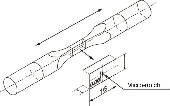
图1
试样几何形状与微缺口尺寸示意图
Fig.1
Schematic of the geometry, and dimensions of the specimen and the micro-notch (unit: mm)
疲劳小裂纹扩展实验系统由载荷加载系统和裂纹监测系统组成,其中载荷加载系统为MTS Landmark Model 370电液伺服测试系统,裂纹监测系统则由光学监测系统和减振系统2个部分组成。图2为实验系统示意图。
图2
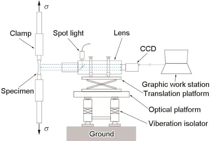
图2
疲劳小裂纹扩展实验系统示意图
Fig.2
Schematic of the experimental system for small fatigue crack propagation (σ—loading, CCD—charge-coupled device camera)
实验载荷为正弦波疲劳载荷,最大应力(σmax)分别选取1200和1000 MPa,应力比为0.3,频率为5 Hz,分别命名为RH试样和RL试样。实验在室温、大气环境下进行。实验开始后经过指定的循环周次,停止加载并将载荷保持在80%最大载荷,对试样表面进行拍照后继续施加疲劳载荷,如此往复,直至实验结束。
疲劳小裂纹扩展实验开展前后,采用配备了电子背散射衍射(EBSD)探测器的Supra55场发射扫描电镜(SEM)对FGH4096材料和试样上含裂纹区域进行微观组织观察与表征。在EBSD测试中,试样的载荷加载方向设定为横向(TD),微缺口所在表面法向设定为轧面法向(ND),EBSD探测器扫描步长为0.2 μm。采用HKL-Channel5软件处理EBSD测试数据。
2 实验结果
2.1 显微组织
图3
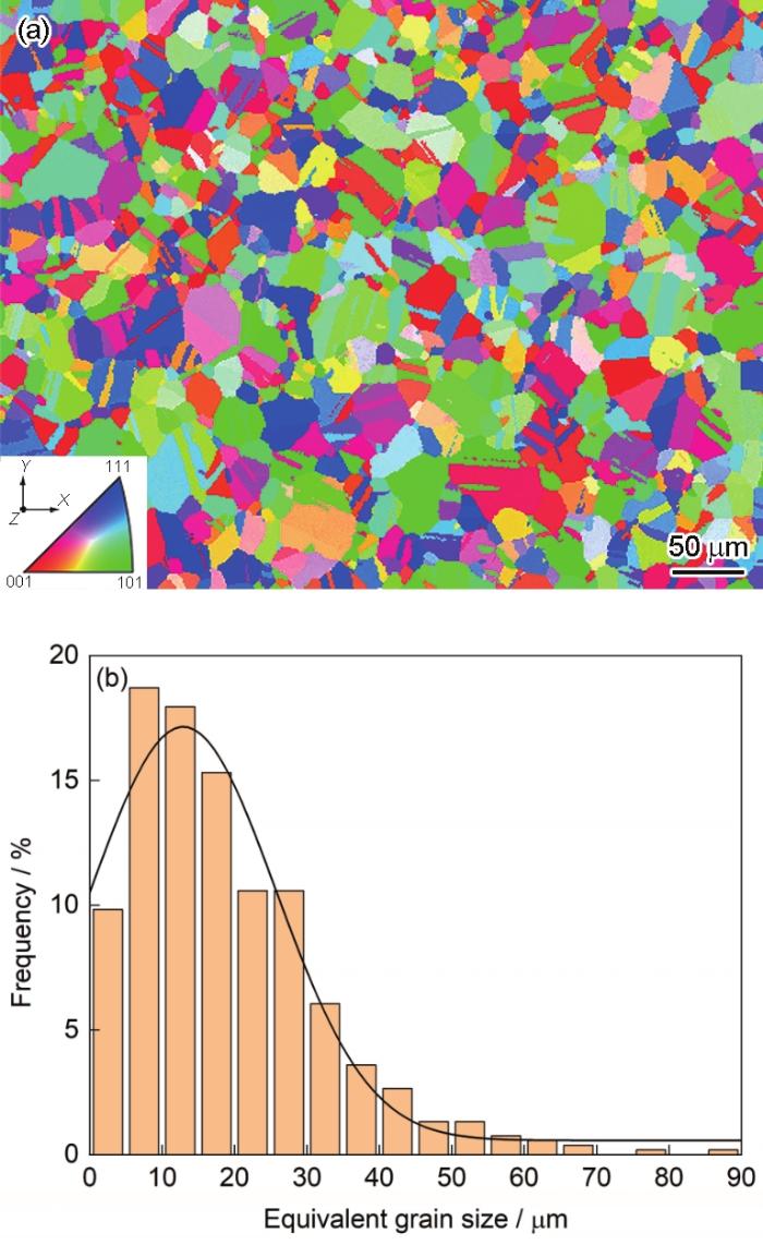
图3
FGH4096高温合金微观组织的反极图(IPF)和等效晶粒尺寸分布统计图
Fig.3
Inverse pole figure (IPF) in Y direction (IPF-Y) coloring map (a) and the distribution of equivalent grain size (b) of FGH4096 superalloy
2.2 小裂纹扩展行为
图4a和b分别为RH和RL试样中小裂纹整体的SEM像。以微缺口为观察基准,在SEM像中,处于微缺口左/右侧的裂纹称为左/右裂纹。可以看出,在RH和RL试样中,小裂纹均从微缺口处萌生,总长度均大于1.0 mm。其中RH试样在小裂纹扩展实验结束后,施加1400 MPa的单调拉伸载荷,使裂纹张开后卸载。
图4
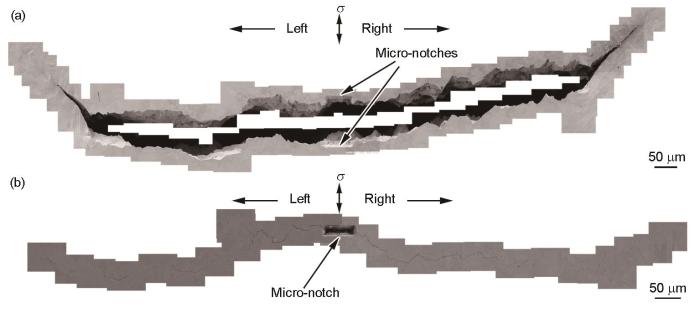
图4
RH和RL试样中小裂纹的SEM像
Fig.4
SEM images of the small crack in RH (a) and RL (b) specimens after the experiment
RH试样中,在循环数N = 1.2 × 10⁴ cyc时,在微缺口左、右边缘均观察到裂纹。RL试样中,在N = 4.0 × 10⁴ cyc时,首先在微缺口左边缘观察到裂纹,但在微缺口右边缘未观察到裂纹;实验至N = 5.55 × 10⁴ cyc时,在微缺口右边缘观察到裂纹。RH和RL试样中的小裂纹总长度到达1.0 mm时所需要的循环数分别为9.2 × 10⁴和2.6 × 10⁵ cyc。
RL试样中微缺口左、右两侧裂纹在扩展过程中均观察到了二次裂纹萌生并与主裂纹连接形成新主裂纹的现象。RH试样中未观察到二次裂纹与主裂纹连接的情况。
图5
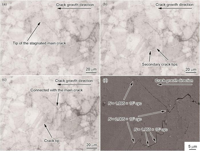
图5
RL试样左侧主裂纹停滞与二次裂纹萌生过程
Fig.5
Stagnation of the left main crack and the initiation of the secondary crack in RL specimen recorded by the experimental system (a-c) and the associated SEM image (d) (N—number of cycle)
(a) the main crack was stagnated at N = 1.895 × 10⁵ cyc
(b) the secondary crack was initiated at N = 1.955 × 10⁵ cyc
(c) the secondary crack connected with the main crack at N = 2.005 × 10⁵ cyc
(d) SEM image of the main area in Figs.5a-c
图6
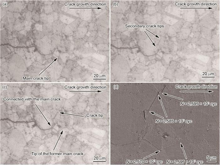
图6
RL试样右侧二次裂纹萌生行为
Fig.6
Propagation of the right main crack and the initiation of the secondary crack in RL specimen recorded by the experimental system (a-c) and the associated SEM image (d)
(a) site of the main crack tip at N = 2.570 × 10⁵ cyc
(b) the secondary crack was initiated at N = 2.585 × 10⁵ cyc
(c) the secondary crack connected with the main crack at 2.595 × 10⁵ cyc
(d) SEM image of the main area in Figs.6a-c
图7
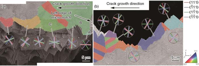
图7
RH试样中小裂纹扩展早期和末期的扩展路径与{111}滑移面迹线分析结果
Fig.7
IPF-Y colored SEM images of the crack path and the associated trace lines of {111} slip planes on the specimen surface in RH specimen
(a) the left crack path from N = 1.20 × 10⁴ cyc to N = 4.42 × 10⁴ cyc
(b) the left crack path from N = 9.052 × 10⁴ cyc to N = 9.268 × 10⁴ cyc
以图7a中小裂纹在晶粒A~C中的扩展为例,小裂纹从微缺口萌生后,在晶粒A中沿
图8
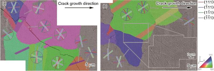
图8
RL试样中小裂纹扩展早期和末期的扩展路径与{111}滑移面迹线分析结果
Fig.8
IPF-Y colored SEM images of the crack path and the associated trace lines of {111} slip planes on the specimen surface in RL specimen
(a) the right crack path from N = 5.550 × 10⁴ cyc to N = 1.085 × 10⁵ cyc
(b) the right crack path from N = 2.62 × 10⁵ cyc to N = 2.64 × 10⁵ cyc
图9
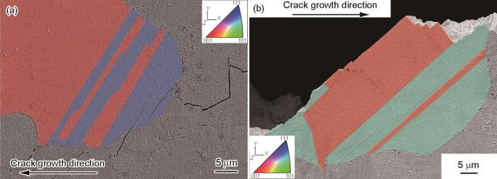
图9
RH和RL试样中小裂纹平行于孪晶界扩展和穿过孪晶扩展的IPF
Fig.9
IPF-Y colored SEM images of the small crack path that paralleled to the trace of twin grain boundary in RL specimen (a) or crossed the twin in RH specimen (b)
2.3 小裂纹停滞行为与局部微观组织
表1 RH和RL试样中小裂纹的停滞情况
Table 1
| Specimen No. | Stagnation site No. | Stagnation state | Consumed cycle | Microstructure in front of the crack tip |
|---|---|---|---|---|
| cyc | ||||
| RH | Left-1 (L1) | Fully | 4.0 × 10³ | GB |
| Left-2 (L2) | Fully | 3.8 × 10³ | TB | |
| Right-1 (R1) | Temporarily | 4.0 × 10³ | GB | |
| RL | Left-1 (L1) | Fully | 9.0 × 10³ | GB |
| Left-2 (L2) | Fully | 5.0 × 10³ | TB | |
| Right-1 (R1) | Temporarily | 1.6 × 10⁴ | GB | |
| Right-2 (R2) | Temporarily | 1.0× 10⁴ | TB |
M因子定义如下[35]:
式中, na 和 da 为晶界一侧晶粒内滑移系的法向和滑移方向(单位向量), nb 和 db 为晶界另一侧晶粒内滑移系的法向和滑移方向(单位向量),下角标a和b是八面体滑移系编号,取值范围1~12。
图10
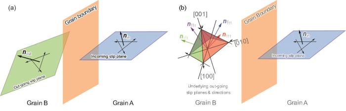
图10
计算M因子时晶界两侧滑移系的2种情况示意图
Fig.10
Schematics of two situations of the slip systems on both sides of the grain boundary when calculating M factor (Incoming slip plane—the slip plane in current grain, out-going slip plane—the slip plane in the grain in front of the grain boundary, nin—the normal direction of incoming slip plane, nout—the normal direction of out-going slip plane,
(a) the slip planes on both sides of the grain boundary are identified
(b) the slip plane in front of the grain boundary is uncertain, all 4 octahedral slip planes should be considered
图11
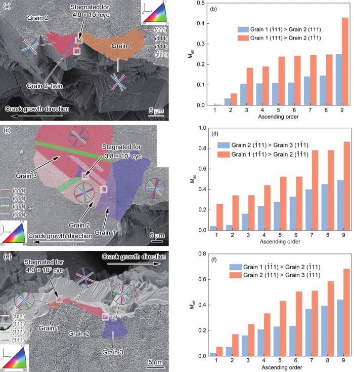
图11
RH试样中小裂纹停滞位置与M因子分析
Fig.11
IPF-Y colored SEM images of the stagnation sites and the associated trace lines of {111} slip planes on the specimen surface (a, c, e) of the small crack in RH specimen and the comparison of M factor (Mab ) (b, d, f)
(a, b) stagnation site L1 (c, d) stagnation site L2 (e, f) stagnation site R1
图12
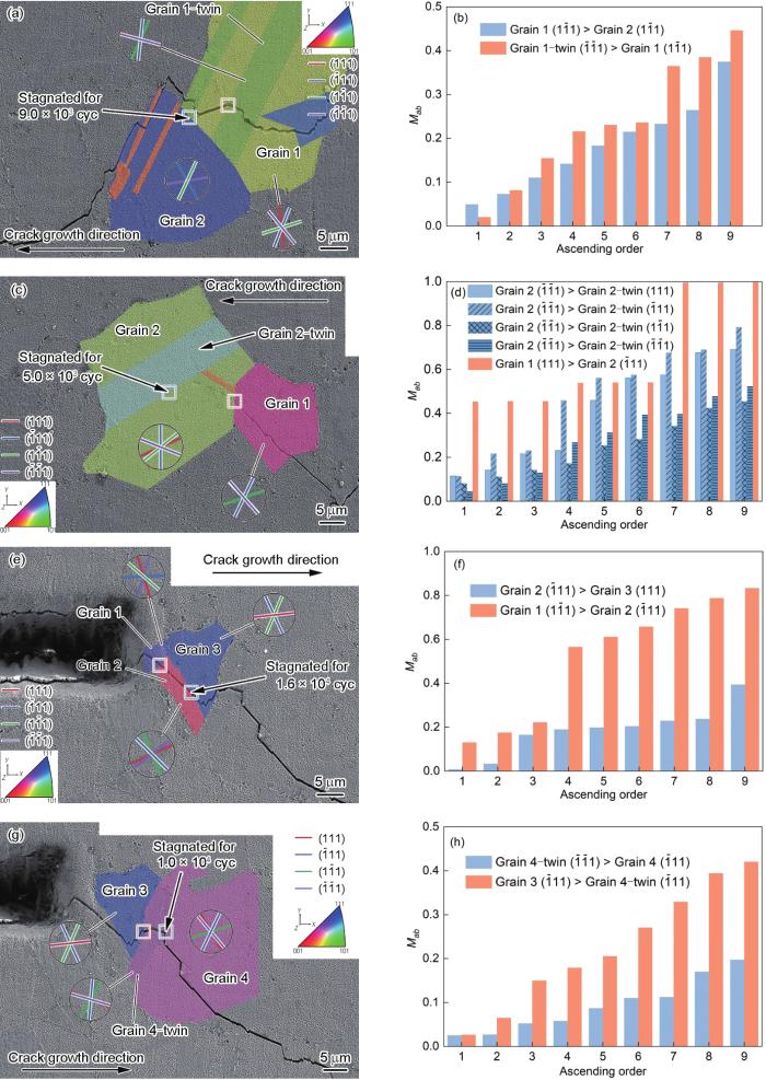
图12
RL试样中小裂纹停滞位置与M因子分析
Fig.12
IPF-Y colored SEM images of the stagnation sites and the associated trace lines of {111} slip planes on the specimen surface (a, c, e, g) of the small crack in RL specimen and the comparison of M factor (b, d, f, h)
(a, b) stagnation site L1 (c, d) stagnation site L2 (e, f) stagnation site R1 (g, h) stagnation site R2
3 分析讨论
3.1 小裂纹的扩展行为与扩展阶段
根据断裂力学理论,小裂纹的种类有[37]:表面中心裂纹深度/半长小于塑性区尺寸时属于力学小裂纹,小于微观组织特征尺寸时属于微观组织小裂纹,裂纹总长度小于5~10倍微观组织特征尺寸或裂纹深度小于1.0 mm时属于物理小裂纹。小裂纹扩展阶段按照扩展机制分为:小裂纹在萌生之后沿单一滑移面的扩展阶段属于Stage Ia阶段;之后小裂纹交替在2个滑移面之间扩展,这属于裂纹扩展的Stage Ib阶段;经历了沿滑移面扩展阶段之后,裂纹进入到沿垂直于最大应力方向扩展的Stage II阶段,并展现出长裂纹的扩展行为特征。裂纹从Stage I向Stage II的转变临界尺寸目前尚无,一般认为裂纹尖端塑性区内有足够多的晶粒使单个晶粒的取向对塑性区整体变形行为影响较小,裂纹不再显著地受到局部微观组织的影响时,裂纹的扩展才开始进入Stage II阶段。
式中,σys为材料的宏观屈服强度,取1100 MPa。计算可得,RH和RL试样对应的ry分别为0.162和0.113 mm,是裂纹半长的32.4%和22.6%,是平均晶粒尺寸的12.5倍和8.7倍。因此从应力强度因子、塑性区的尺寸和包含的晶粒数量来看,小裂纹长度在到达1.0 mm后的扩展应进入Stage II阶段。但是从图7和8可以看出,裂纹在长度到达1.0 mm之后,仍保持沿滑移面扩展的行为,并没有进入Stage II扩展阶段,可以判断此时小裂纹的扩展行为仍将显著地受到微观组织(如晶界)的影响。因此,从小裂纹仍沿晶体学平面扩展这一行为来看,此时小裂纹的扩展仍未进入Stage II扩展阶段。
3.2 小裂纹的扩展停滞行为及其机理
从断裂物理角度来看,作为一类由位错运动控制的裂纹,小裂纹尖端前沿的位错与微观组织的交互作用对裂纹扩展行为具有显著的影响,特别是位错与晶界的交互作用。Zhai等[30]提出采用与晶界两侧晶粒取向以及晶界面取向相关的扭转角和倾斜角来表征晶界抵抗小裂纹扩展的强度。其中对小裂纹扩展影响更大的扭转角与晶界面的空间取向有关,而晶界面取向是大多数表征手段难以获得的。M因子是一种在位错-晶界交互作用研究中常用的“滑移穿越准则(slip transmission criterion,STC)”,以滑移面法向夹角和滑移方向夹角表征位错穿越晶界的难易程度[34]。该因子与难以获知的晶界面取向无关,能够通过纳入了滑移方向夹角间接反映晶界残余Burgers矢量,该矢量是位错穿越晶界的决定性因素之一[40]。小裂纹与晶界交互作用的研究[36]结果表明,小裂纹是倾向于沿着能够最小化晶界残余Burgers矢量的滑移方向穿越晶界的。因而M因子在无需知晓晶界面取向的情况下也能较好地表征晶界阻碍位错穿越的能力。从图11和12来看,小裂纹在晶界和孪晶界发生扩展停滞,通过计算裂纹所在晶粒和下一个晶粒(裂纹前沿晶粒)的M因子,可以发现这些M因子与那些对裂纹扩展没有阻碍的晶界的M因子相比都较小,而M因子越小代表着位错穿越晶界越困难。这表明M因子可以用作表征晶界抵抗小裂纹扩展的强度。
小裂纹在扩展过程中发生停滞之后的第一种和第二种行为与晶界/孪晶界性质有关。由于阻碍裂纹扩展的晶界/孪晶界性质不同,位错与这些晶界的交互作用结果也不同。Genée等[41]的研究结果显示,对于大角度晶界,位错无法直接穿越,由此形成的滑移带与晶界的交互作用导致“微体积(micro-volume)”在下一个晶粒内紧邻当前晶界形成。根据Larrouy等[34]的研究结果,“micro-volume”形成的必要条件之一是扭转角不小于55°,并且“micro-volume”就是下一个晶粒内疲劳裂纹的萌生位置。当晶粒经过足够多的循环后,形成“micro-volume”,使得下一个晶粒内出现疲劳裂纹,此时当前晶粒内的裂纹与下一个晶粒内萌生的裂纹连接并穿越当前晶界,这一类型的位错-晶界交互机制是形成第一种扩展行为的原因;第二种扩展行为是由于裂纹穿越当前晶界需要的循环数较多,在裂纹停滞期间,在当前晶粒内次优的滑移系上,或者裂纹路径上某晶粒的有利取向滑移系上萌生出裂纹继续扩展;第三种行为则与裂纹停滞循环数有关,由于RH试样的最大应力高于RL试样,并且接近实验材料室温屈服强度范围上限,在相同裂纹长度条件下,其裂纹扩展驱动力要高于RL试样,扩展速率也更高。当裂纹遇到具有显著阻碍作用的晶界/孪晶界时,RH试样中的裂纹消耗更少的循环数就能穿越晶界继续扩展或者转到另一滑移面继续扩展。如表1所示,RH试样中裂纹停滞消耗的循环数都低于RL试样。因此,在RH试样中,主裂纹的扩展受到微观组织阻碍频次较少。裂纹受到微观组织阻碍发生停滞之后,在裂纹尖端附近晶粒内处于有利取向的滑移系持续累积剪切应变。若主裂纹停滞的循环数大于这些滑移系萌生裂纹需要消耗的循环数,那么二次裂纹将萌生并扩展。如图5和6所示,二次裂纹均萌生于主裂纹尖端附近1~2个晶粒尺寸范围内。若在二次裂纹萌生之前,主裂纹继续扩展,那么这些滑移系不再处于裂纹尖端应力场之内,剪切应变累积速率也迅速下降,二次裂纹很可能无法萌生。由于RH试样中小裂纹扩展速率更高,受到阻碍频次较少,程度较低,因此在RH试样中出现二次裂纹萌生以及连接主裂纹现象出现的可能性也更低。综上所述,小裂纹在扩展停滞后的行为是受到晶界/孪晶界的阻碍能力与载荷共同控制的。
4 结论
(1) 在2种载荷条件下,FGH4096高温合金中的小裂纹自萌生开始沿单个或交替沿2个八面体滑移面进行扩展,处于Stage I扩展阶段,即使在裂纹总长度大于1.0 mm时,小裂纹的这一扩展行为仍保持不变。
(2) 小裂纹与晶界/孪晶界的交互作用导致裂纹扩展停滞,与周围没有阻碍作用的晶界/孪晶界的M因子相比,这些晶界/孪晶界的M因子都较低,M因子可以用于描述晶界/孪晶界抵抗小裂纹扩展的能力。
(3) 晶界/孪晶界对小裂纹的阻碍能力以及疲劳载荷共同决定了小裂纹在停滞后的扩展行为。对于2种疲劳载荷而言,小裂纹在停滞后都存在继续消耗一定循环数进入下一个晶粒或从主裂纹萌生出新裂纹继续扩展的行为,而当最大应力接近实验材料屈服强度下限时,二次裂纹萌生所需的循环数低于小裂纹穿越具有强阻碍作用的晶界/孪晶界所需的循环数,这是导致只有RL试样中左、右侧裂纹均出现二次裂纹萌生并与主裂纹连接的原因。
参考文献
Nickel-based superalloys for advanced turbine engines: Chemistry, microstructure and properties
[J].
A fatigue life model for predicting crack nucleation at inclusions in Ni-based superalloys
[J].
Microstructural features controlling the variability in low-cycle fatigue properties of alloy Inconel 718DA at intermediate temperature
[J].
A new paradigm of fatigue variability behavior and implications for life prediction
[J].
Investigation of fatigue crack initiation from a non-metallic inclusion via high energy X-ray diffraction microscopy
[J].
Competing fatigue mechanisms in nickel-base superalloy Rene 88DT
[D].
Fracture character of low cycle fatigue of P/M superalloy FGH97
[J].
粉末冶金高温合金FGH97的低周疲劳断裂特征
[J].
Effects of microstructure on long and short crack growth in nickel base superalloys
[J].
Small fatigue crack growth and failure mode transitions in a Ni-base superalloy at elevated temperature
[J].
Fatigue crack initiation and short crack growth in nickel-base turbine disc alloys-the effects of microstructure and operating parameters
[J].
X-ray characterization of the micromechanical response ahead of a propagating small fatigue crack in a Ni-based superalloy
[J].
The small fatigue crack (SFC) growth regime in polycrystalline alloys is complex due to the heterogeneity in the local micromechanical fields, which result in high variability in crack propagation directions and growth rates. In this study, we employ a suite of techniques, based on high-energy synchrotron-based Xray experiments that allow us to track a nucleated crack, propagating through the bulk of a Ni-based superalloy specimen during cyclic loading. Absorption contrast tomography is used to resolve the intricate 3D crack morphology and spatial position of the crack front. Initial near-field high-energy X-ray diffraction microscopy (HEDM) is used for high-resolution characterization of the grain structure, elucidating grain orientations, shapes, and boundaries. Cyclic loading is periodically interrupted to conduct far-field HEDM to determine the centroid position, average orientation, and average lattice strain tensor for each grain within the volume of interest. Reciprocal space analysis is used to further examine the deformation state of grains that plasticize in the vicinity of the crack. Analysis of the local micro-mechanical state in the grains ahead of the crack front is used to rationalize the advancing small crack path and growth rate. Specifically, the most active slip system in a grain, determined by the maximum resolved shear stress, aligns with the crack growth direction; and the degree of microplasticity ahead of the crack tip helps to identify directions for potential occurrences of crack arrest or propagation. The findings suggest that both the slip system level stresses and microplasticity events within grains are necessary to get a complete description of the SFC progression. Further, this detailed dataset, produced by a suite of X-ray characterization techniques, can provide the necessary validation, at the appropriate length-scale, for SFC models. (C) 2019 Acta Materialia Inc. Published by Elsevier Ltd.
Study on small crack propagation behavior and life prediction of FGH96 powder superalloy
[D].
FGH96粉末高温合金疲劳小裂纹扩展行为及寿命预测研究
[D].
Modelling of short crack propagation-Transition from stage I to stage II
[J].
The influence of microstructure on the growth of small fatigue cracks
[J].
Microstructural mechanisms and advanced characterization of long and small fatigue crack growth in cast A356-T61 aluminum alloys
[J].
Effect of microstructure on small fatigue crack initiation and early propagation behavior in Mg-10Gd-3Y-0.3Zr alloy
[J].
A grain boundary interaction model for microstructurally short fatigue cracks
[J].
An investigation of the small fatigue crack growth behavior in Ti-6.5Al-2Zr-1Mo-1V alloy
[J]. J.
Effect of the presence of macrozones on short crack propagation in forged two-phase titanium alloys
[J].
Effect of microstructural features on short fatigue crack growth behaviour in SA508 Grade 3 Class I low alloy steel
[J].
Strain accumulation during microstructurally small fatigue crack propagation in bcc Fe-Cr ferritic stainless steel
[J].
A 3-D view on the mechanisms of short fatigue cracks interacting with grain boundaries
[J].
Integrated experiment and modelling of microstructurally-sensitive crack growth
[J].
Nanostructurally small cracks (NSC): A review on atomistic modeling of fatigue
[J].
The influence of the grain structure size on microstructurally short cracks
[J]. J.
Microstructural extremes and the transition from fatigue crack initiation to small crack growth in a polycrystalline nickel-base superalloy
[J].
A crystallographic mechanism for fatigue crack propagation through grain boundaries
[J].
Crossing grain boundaries in metals by slip bands, cleavage and fatigue cracks
[J].
Influence of twist angle on crack propagation of nanoscale bicrystal nickel film based on molecular dynamics simulation
[J].
Grain boundaries and interfaces in slip transfer
[J].
Grain boundary-slip bands interactions: Impact on the fatigue crack initiation in a polycrystalline forged Ni-based superalloy
[J].
Compatibility of deformation in two-phase Ti-Al alloys: Dependence on microstructure and orientation relationships
[J].
Predicting the 3D fatigue crack growth rate of small cracks using multimodal data via Bayesian networks: In-situ experiments and crystal plasticity simulations
[J]. J.
Small fatigue cracks: A statement of the problem and potential solutions
[J].
An empirical stress-intensity factor equation for the surface crack
[J].
Dislocation interactions with grain boundaries
[J].
Slip transfer across grain/twin boundaries in polycrystalline Ni-based superalloys
[J].
