


超细晶/纳米晶材料由于其具有小尺寸效应、大量无序结构的晶界特征和优异的性能,备受关注。在其成形方法中,尤其以剧烈塑性变形(severe plastic deformation,SPD)技术[1]的研究成果较显著,被公认是最具工业化应用前景的方法。依据成形特点,主流的SPD技术包括等径角挤压(ECAP)、高压扭转(HPT)、累积叠轧(ARB)[2,3]、多向锻造(MF)和扭转挤压(TE)[4~6] 5种,以及依托上述技术衍生的数百种方法[7,8]。变形前后几何尺寸发生明显变化的(称变化型)主要包括HPT[9]、ARB、MF等,无明显改变的(称不变型)主要包括ECAP、TE、限定型HPT等。块体材料制备最具代表性方法为ECAP和HPT。
虽然SPD新方法层出不穷,但至今仍处于实验室研究阶段,未能实现真正意义的工业化应用。主要原因是:该方法一般在远离再结晶温度的低温下进行,以这种方式获得的大角度晶界的热稳定性显著下降;成形载荷巨大,有效变形区体积受限,现有成形设备一般不具备工业化大尺寸制品的超过几十吉帕单位压力的加载能力;变形不均匀性严重,致使晶粒尺度不均匀明显,相应性能降低。
本工作为获得45钢块体超细晶棒材,基于斜轧原理,提出了一种新的SPD成形方法,称为3D-SPD法。构建了用于棒材轧制的近单锥形剧烈扭转压缩复合变形区,以兆帕级单位成形载荷,实现了块体SPD。建立了基于Oyane损伤准则[25]的裂纹萌生控制模型,有效抑制了因Mannesmann效应(ME,通常指旋转压缩实心圆柱体时,受拉应力作用中心部位会产生孔腔的物理现象)的裂纹萌生。根据刚塑性有限元模拟法,优化了变形区形状及变形参数。利用自主研发的3D-SPD成形设备,采用单道次轧制法,成功制备了平均晶粒尺寸细化至约1 μm的棒材,其力学性能大幅提升。
1 模型与方法
本工作主要研究了3D-SPD法轧制中碳钢块体超细晶棒材的成形原理。首先对变形特点开展研究,系统分析了3D-SPD法与传统斜轧法及纵轧法的主要区别,基于刚塑性有限元原理,分别建立了上述不同成形方法的计算模型。其中3D-SPD法,以45钢为研究对象,建立了如图1所示的模型,坯料咬入变形区后,在三维空间旋出了由平均直径逐渐减小的近椭圆锥体形,逐渐演变为圆锥体形,再到圆柱体形的复杂扭转压缩复合变形区,做螺旋运动。
图1

图1
3D-SPD有限元模型示意图
Fig.1
Schematics of 3D severe plastic deformation (3D-SPD) finite element model from views of front (a), left (b), and top (c) (n—roll speed, α—cone angle, β—feed angle, γ—cross angle, Vx—feeding direction)
为了深入解析3D-SPD法在棒材轧制上的应用,本工作还开展了以严苛抑制ME为轧制条件的研究,实现了杜绝棒材心部萌生裂纹、长大及形成孔腔的目标。
关于裂纹的表征基于Oyane损伤准则(
式中,D为材料断裂阈值,即损伤值;
基于该条件,并结合有限元分析,可计算任意塑性成形过程变形体内的损伤值,损伤值越大,其裂纹萌生的可能性越高。为此,结合有限元计算模型,分别建立了传统斜轧法与3D-SPD法的损伤值计算模型,通过对比分析明确了抑制ME的变形条件。
为确定满足超细晶棒材成形的变形参数,本工作开展了综合分析损伤、应变及变形温度的优化法,在保证棒材心部不裂的前提下,以应变大且分布均匀、变形温度合理且温差较小为目标,优选了最佳工艺参数,并利用自主研发的3D-SPD轧机成功制备了超细晶棒材。采用LWD300LT型光学显微镜(OM)进行组织观察,利用Instron3382电子万能材料试验机进行拉伸实验。
2 结果及讨论
2.1 3D-SPD变形特点
3D-SPD轧制法源于传统锥形辊斜轧法,但在以下几方面有特殊性。(1) 变形区形状:传统法变形区为近双锥形,常因有效利用ME而在用于穿孔无缝管,但也正因ME易诱发心部裂纹萌生,不用于棒材轧制,而是采用纵轧法轧制棒材;3D-SPD变形区为近单锥形,可实现径缩率超过50%的SPD (图2)。(2) 轧辊形状:传统法为双锥形;3D-SPD为近单锥形特殊曲面轧辊。(3) 轧制方向:传统法坯料从轧辊直径最小端咬入;3D-SPD从轧辊直径最大端咬入,随着接触变形区轧辊直径的逐渐减小,轧辊沿轧件前进方向的分速度逐渐降低,轧件前进受阻,可降低金属沿轴向的变形不均性,减弱轧件心部拉应力分布,弱化ME,防止诱发裂纹。(4) 变形参数:如表1所示,3D-SPD采用的辊面锥角α约为传统法[26]的2倍,可加倍提高直径压缩变形速率;送进角β为传统法的1.5~2倍,可明显增加轧件在变形区的螺距,减少反复交变变形次数,抑制ME,避免轧件心部裂纹的萌生;径缩率为传统法的3倍以上,传统法用于穿孔,外径变化不明显,而3D-SPD是可实现直径收缩的SPD;3D-SPD的椭圆度系数(导板距/辊距)更接近1.0,可显著限制横向宽展变形,减弱ME,抑制轧件心部裂纹的萌生。
图2

图2
3D-SPD与传统斜轧法变形区对比图
Fig.2
Comparisons of deformation zones between 3D-SPD (a) and traditional cross-rolling (b)
表1 3D-SPD与传统斜轧法工艺参数[26]对比
Table 1
| Process | α / (°) | β / (°) | Reduction rate / % | Ovality factor |
|---|---|---|---|---|
| 3D-SPD | 4-6 | 20-24 | 35-55 | 1.02-1.05 |
| Traditional cross-rolling[26] | 1-3 | 8-15 | ±5-10 | 1.10-1.20 |
2.2 严苛抑制ME的变形条件
图3
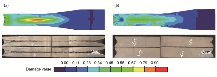
图3
传统斜轧与3D-SPD制备的试样的损伤值计算结果及纵截面形貌
Fig.3
Calculated damage values (upper) and longitudinal section morphologies (lower) of samples fabricated by traditional cross rolling (a) and 3D-SPD (b)
2.3 累积剧烈塑性应变
图4

图4
传统纵轧与3D-SPD等效应变对比
Fig.4
Comparisons of equivalent strain between traditional longitudinal rolling (a) and 3D-SPD (b)
3D-SPD的剧烈塑性应变累积与剧烈扭转变形密切相关。假设用变形前后任意质点的扭转角表征扭转变形程度,图5a和b分别为传统斜轧与3D-SPD的扭转角对比。3D-SPD的扭转角为240°,远大于传统斜轧的150°,可见,3D-SPD的扭转变形剧烈。
图5
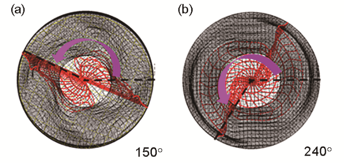
图5
传统斜轧与3D-SPD扭转角对比
Fig.5
Comparisons of torsion angles between traditional cross rolling (a) and 3D-SPD (b)
2.4 低成形载荷
图6

图6
传统纵轧与3D-SPD轧制负荷对比
Fig.6
Comparisons of forces (a) and torques (b) between traditional longitudinal rolling and 3D-SPD
2.5 3D-SPD超细晶成形工艺参数优化
图7
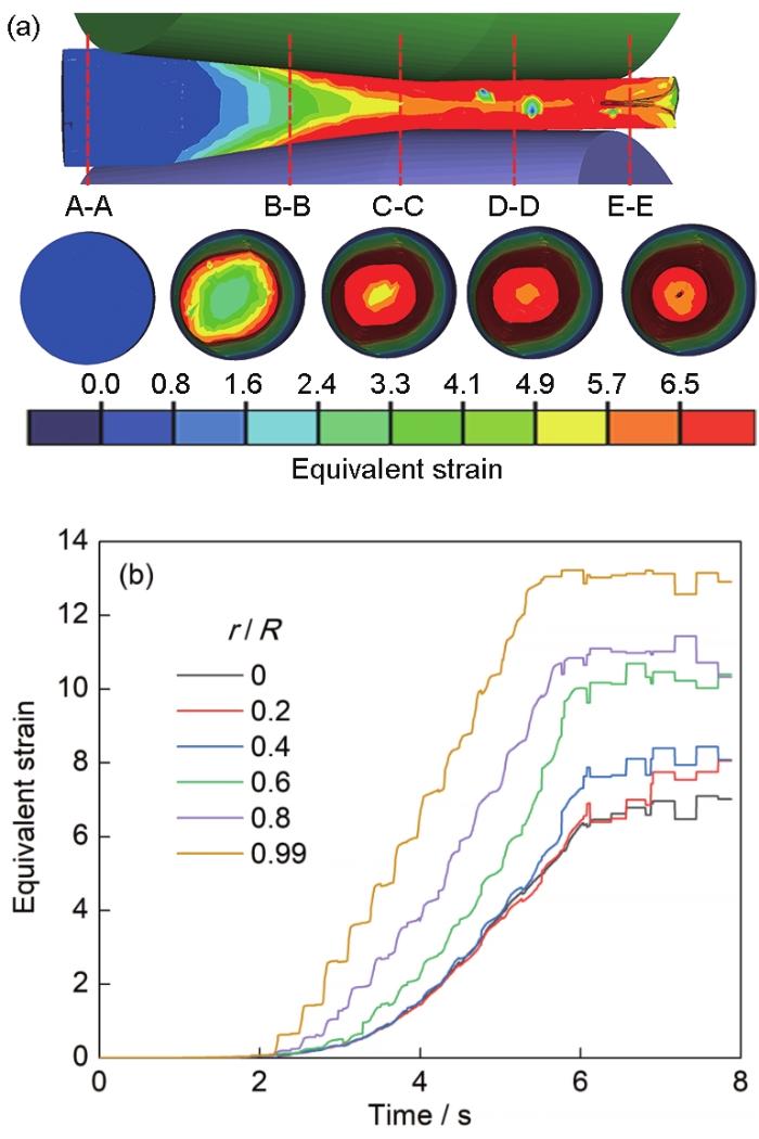
图7
3D-SPD等效应变及等效应变随时间的变化
Fig.7
Equivalent strains in 3D-SPD process (a) and changes of equivalent strain with time (b) (r—distance between tracking point and rolling line, R—bar radius)
在3D-SPD成形过程中,表层金属在轧辊压力作用下首先产生塑性变形,并随变形程度增大逐渐向心部渗透,沿轧件径向等效应变呈“U”型分布;沿轧件轴向,应变随变形程度的增大而逐渐增大。轧件表层应变最大(约为13.0),心部应变最小(大于6.5)。轧件即将离开变形区时,从内到外应变分布均匀。因此,该工艺条件下的单道次3D-SPD成形可预期将晶粒尺寸细化至超细晶状态。
图8
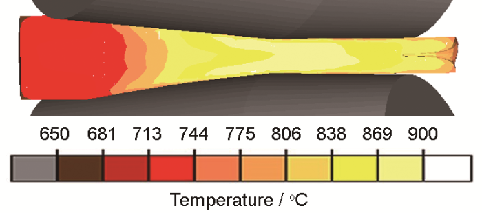
本工作最终优选了对应图7及8的变形参数:送进角24°、辗轧角15°、辊面锥角5°、径缩率50%、椭圆度系数1.02、温度700℃以及轧辊转速40 r/min。
2.6 超细晶棒材制备
图9
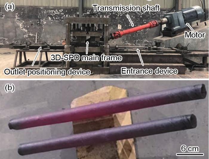
图9
自制3D-SPD试验机及轧后45钢棒材
Fig.9
Homemade 3D-SPD testing machine (a) and 45 steel bars after rolling (b)
图10所示为45钢轧前及轧后+水淬的显微组织的OM像。由图可得,初始棒材坯料的平均晶粒尺寸约为46 μm,轧后棒材平均晶粒尺寸约为1 μm,晶粒细化显著,细化程度约至1/50。
图10

图10
45钢轧制前后的显微组织
Fig.10
Microstructures of 45 steel before (a) and after (b) rolling
从3D-SPD轧制前后棒材上,分别在中间位置按照国标要求制备了拉伸试样,其拉伸应力-应变曲线如图11所示。在恒应变速率下,测得原始坯料屈服强度为324.45 MPa,抗拉强度为609.19 MPa,延伸率为22.6%;经3D-SPD后,试样屈服强度和抗拉强度分别达到475和862 MPa,延伸率17.1%。屈服强度和抗拉强度分别提升46%和42%,均有显著升高;延伸率降低5.5%,损失较小。
图11

图11
45钢轧制前后的拉伸应力-应变曲线
Fig.11
Stress-strain curves of 45 steel before and after rolling (The inset shows the specific fracture position of the sample before and after rolling)
3 结论
(1) 提出了一种SPD成形方法,称为 3D-SPD法。基于斜轧原理,利用特殊曲面锥形轧辊及导板,并由辊径大端进料,采用超大送进角,实现了单道次径缩率50%以上的剧烈扭转压缩复合变形,用于成形块体超细晶棒材。
(2) 确定了基于Oyane准则的3D-SPD损伤预测模型,构建了能严格抑制ME的变形区,实现了对棒材内部裂纹萌生现象的控制,建立了超细晶棒材成形的前提条件。
(3) 基于剧烈扭转压缩复合变形,3D-SPD法的等效应变累积效果显著,单道次轧制成形超细晶棒材,单位压力仅需兆帕级,其工业化生产可能性大幅提升。
(4) 采用送进角24°、辗轧角15°、辊面锥角5°、径缩率50%、椭圆度系数1.02、温度700℃以及轧辊转速40 r/min等变形参数,成功制备了直径25 mm的、晶粒尺寸由46 μm细化至1 μm的45钢块体超细晶棒材,轧后屈服强度提升46%,抗拉强度提升42%,且塑性损失较小。
参考文献
A critical evaluation of the processing of an aluminum 7075 alloy using a combination of ECAP and HPT
[J].
Novel ultra-high straining process for bulk materials—Development of the accumulative roll-bonding (ARB) process
[J].
Ultra-fine grained bulk steel produced by accumulative roll-bonding (ARB) process
[J].
Extreme grain refinement by severe plastic deformation: A wealth of challenging science
[J].
The occurrence of ideal plastic state in CP titanium processed by twist extrusion
[J].
Metal plasticity during the twist extrusion
[J].
Equidistant screw rolling method for large-size 45 steel superfine crystal bar
[P].
一种大尺寸45钢超细晶棒材的等距螺旋轧制方法
[P].
一种F+P型非调质钢的3D-SPD超细晶棒材成形方法
[P].
Using high-pressure torsion for metal processing: Fundamentals and applications
[J].
Plastic working of metals by simple shear
[J].
Materials processing by simple shear
[J].
Severe plastic deformation: simple shear versus pure shear
[J].
Slip line solutions, deformation mode and loading history during equal channel angular extrusion
[J].
Deformation mode and plastic flow in ultra fine grained metals
[J].
Exploring performance limits of a new martensitic high strength steel by ausforming via equal channel angular pressing
[J].
Preform effect on the plastic deformation behavior of workpieces in equal channel angular pressing
[J].
High-pressure torsion of titanium at cryogenic and room temperatures: Grain size effect on allotropic phase transformations
[J].
Influence of phase volume fraction on the grain refining of a Ti-6Al-4V alloy by high-pressure torsion
[J].
Influence of high-pressure torsion straining conditions on microstructure evolution in commercial purity aluminum
[J].
Grain refinement of medium carbon steel with controlled thermo-mechanical deformation
[A].
Effect of caliber rolling reduction ratios on the microstructure and mechanical properties of 45 medium carbon steel
[J].
A thermomechanical process to achieve mechanical properties comparable to those of quenched-tempered medium-C steel
[J].
Criteria for ductile fracture and their applications
[J].
金属塑性加工学
[M]. 第
Research on large-bar continuous rolling process and rolling model
[J].
大规格棒材连轧工艺及轧制模型研究
[J].
Numerical simulation study on ultra-fine grained rod rolling of medium carbon steel
[D].
中碳钢超微细晶棒材轧制数值模拟研究
[D].
Bulk nanostructured materials from severe plastic deformation
[J].
