
石晶, 郭振玺, 隋曼龄
北京工业大学固体微结构与性能研究所, 北京 100124
SHI Jing, GUO Zhenxi, SUI Manling
中图分类号: TG146.2
通讯作者:
收稿日期: 2015-05-21
修回日期: 2015-10-12
网络出版日期: --
版权声明: 2016 《金属学报》编辑部 版权所有 2014, 金属学报编辑部。使用时,请务必标明出处。
基金资助:
作者简介:
石晶, 女, 1988年生, 硕士
展开
摘要
利用聚焦离子束(FIB)对hcp结构金属a-Ti进行纳米尺寸单晶拉伸样品定向切割, 利用特制的双金属片拉伸器在TEM中将单晶样品沿[2110]方向进行原位拉伸. 结果表明, 在拉伸过程中, 随着应变量的增加, a-Ti先后产生了3类不同Burgers矢量的滑移位错: 柱面<a>位错及2类锥面<c+a>位错, 滑移位错的Burgers矢量主要通过原位TEM双束衍衬像确定. 针对hcp结构的低对称性和Burgers矢量可能与多种滑移面相组合的特点, 先利用TEM与EBSD确定晶体取向以及样品的拉伸方向, 再通过计算位错Burgers矢量对应的多个滑移系的Schmid因子, 确定a-Ti拉伸变形过程中开动的滑移系.
关键词:
Abstract
Titanium and its alloys have been widely used in automotive industry and aerospace field due to their high mechanical strength and low density. It has been known that a-Ti has an hcp crystal structure and silp in hcp structure is limited because of only 3 independent slip systems. Therefore, twinning is active in hcp structure and the deformation behavior of hcp metals is very complex by the presence of both dislocation slip and twinning. In sub-micron sized a-Ti sample, deformation twins are difficult to produce and the deformation mechanism is mainly dislocation slip. However, it is hard to identify the activated dislocation slip system in a-Ti, as a few avaliable slip planes is corresponding to one slip direction. Usually there are two ways to identify the activated slip systems. One is to deduce the slip plane and the slip direction based on the loading direction and the crystal orientation. But this method is not accurate because of many possible groups of slip planes and slip directions in hcp structure. The other one is judging the Burgers vector of the dislocation under certain diffraction vectors based on Bragg's law by using TEM. It takes time and can only determine the slip direction of dislocation. Therefore, it is important to find an effective method to identify the active slip system more simply and accurately during deformation process. In this work, a nanometer sized tensile sample of a-Ti single crystal was fabricated by using focused ion beam (FIB) technique. In situ tensile test was carried out along [2110] of a-Ti sample by using a homemade bimetal stretching device in TEM. It has been found that three types of the dislocations, one prismatic <a> dislocation and two pyramidal <c+a> dislocations, were activated in order with strain increasing during tensile process.The Burgers vectors of dislocations were determined by two-beam diffraction contrast imaging in TEM. For hcp structure, one Burgers vector may have the characteristics of a variety of slip planes. By EBSD technique, the crystalline orientation and the loading direction in TEM were indexed accurately and Schmid factors for all the possible slip systems were calculated corresponding to each Burgers vector. Then, the activated slip systems during in situ TEM tensile process are determined by Burgers vector and Schmid factor. This work offers an effective method to identify the activated slip system during tensile process and get more understanding about the plastic deformation mechanism of a-Ti and hcp metals.
Keywords:
Ti及钛合金因其机械强度高、密度小等优点在汽车工业、航空航天等领域具有广泛的应用前景, 因此对其微观结构以及塑性变形机理的研究倍受关注[1-5]. a-Ti具有hcp结构, 对称性较低, 独立滑移系少, 孪生切变作用明显, 因此塑性变形行为复杂[6-8]. 但在a-Ti单晶样品变形过程中, 由于样品尺寸较小, 形变孪晶不容易产生, 故位错成为其主要变形机制[9]. 因为位错滑移系存在多种可能的滑移面(基面、柱面、锥面)与滑移方向(<a>, <c>, <c+a>)的组合, 所以a-Ti单晶样品变形机制相当复杂. 因而, 确定a-Ti塑性变形时开动的滑移系显得极为重要.
目前, 确定单晶样品变形时开动的滑移系有以下几种方法: 一种是利用扫描电镜(SEM)及力学加载方向确定滑移系. Gong和Wilkinson[10]对a-Ti单晶微米尺度悬臂梁沿c轴方向进行压缩, 考虑悬臂梁的几何尺寸和旋转角度, 再依据滑移方向与悬梁顶端夹角确定
总之, 对位错滑移系的确定目前仍有难度. 一种是利用力学加载方向和晶面取向图确定滑移面和滑移方向, 但由于hcp结构中滑移面和滑移方向可能的组合太多, 此方法确定滑移系的准确性不够; 另一种是利用TEM进行多个衍射矢量的判断, 此方法不仅对样品和TEM操作者技术要求较高, 而且一般只能确定滑移方向, 不能确定滑移面. 本工作利用TEM技术与电子背散射衍射(EBSD)技术相结合方法, 对a-Ti可能开动的滑移系进行分析, 确定位错所在的滑移系, 为研究hcp结构中复杂的位错变形机制, 特别是对研究微米及纳米尺寸样品原位塑性变形中位错滑移系开动的新现象与新规律提供了一种很有效的方法.
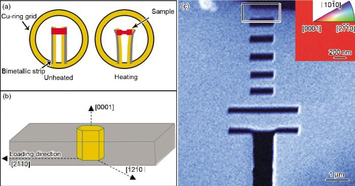
实验所用样品为a-Ti, 其化学成分(质量分数, %)为: Al 0.6, S 0.12, O 0.19, Ti余量, 平均晶粒尺寸约为30 mm. 利用MTP-1A型电解双喷减薄仪和5%高氯酸+95%甲醇(体积分数)的电解液将a-Ti减薄制成TEM样品, 实验温度-30 ℃, 电压15 V. 将TEM样品薄区剪切下来, 粘到原位TEM拉伸基片之间(基片为自行研制的双金属片, 用于双轴倾转的原位TEM拉伸装置), 示意图如图1a所示. 利用NanoLab 600i场发射双束聚焦离子束(FIB)扫描电镜在拉伸基片上的样品薄区内刻制出多条宽度为300~400 nm, 长为1 mm的纳米尺寸拉伸样品, 如图1c所示. 利用JSM-6500F场发射扫描电镜的EBSD技术, 分别测定样品的晶体学取向和双金属片拉伸装置的水平拉伸方向. 从EBSD结果的取向信息和样品轧制方向可以判定纳米尺寸拉伸样品为单晶, 表面平行于基面(0001), 拉伸方向是
图1 TEM双金属片拉伸器、样品晶体学取向和应力加载方向示意图以及聚焦离子束(FIB)加工后a-Ti样品的SEM像
Fig.1 Schematics of bimetallic extensor in TEM (a), crystallographic orientation and loading direction (b) and SEM image of a-Ti sample prepared by focused ion beam (FIB) (c) (Inset in Fig.1c corresponds to EBSD image of the rectangle area)
在原位拉伸加载之前, 将a-Ti单晶样品倾转到满足g=
图2 a-Ti单晶原位拉伸变形过程中的TEM视频截图
Fig.2 TEM video frames of a-Ti single crystal with strains of 0% (a), 3.43% (b), 7.31% (c) and 4.63% (d) during tensile deformation (Sample marks are indicated by the arrows)
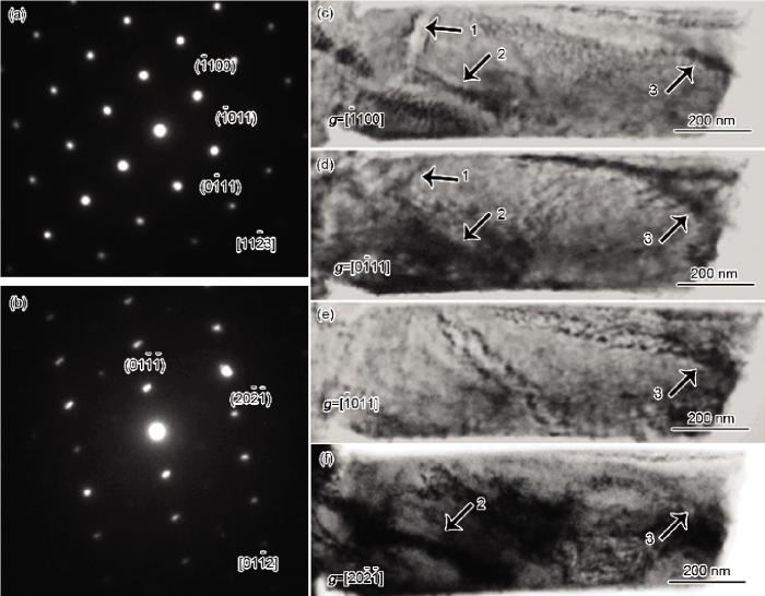
对拉伸变形断裂a-Ti样品中残留的位错进行SAED及双束衍衬像分析, 结果如图3所示. 图3a和b分别是a-Ti形变样品沿
图3 a-Ti单晶拉伸变形后的SAED谱和衍射矢量为g= [1ˉ100] , g= [01ˉ11] , g= [1ˉ011] 和g= [202ˉ1ˉ] 的双束衍衬像
Fig.3 SAED patterns along crystal zone axis of [112ˉ3] (a), [011ˉ2] (b) and two-beam diffraction contrast images under diffraction vectors g= [1ˉ100] (c), g= [01ˉ11] (d), g= [1ˉ011] (e) and g= [202ˉ1ˉ] (f) of a-Ti single crystal after TEM tensile deformation
图4 a-Ti单晶在拉伸过程中<a>位错滑移的TEM视频截图
Fig.4 TEM video frames for <a> dislocation slip in a-Ti single crystal with strains of 0% (a), 0.44% (b), 1.44% (c), 2.84% (d), 5.21% (e) and 7.31% (f) during tensile deformation (Arrows show the movement of the dislocation)
图3c中2号位错线在g=
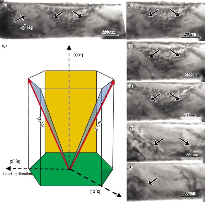
图5 a-Ti单晶在拉伸过程中2号位错<c+a>滑移的TEM视频截图及加载方向与晶体取向原理图
Fig.5 Initial TEM image (a) and TEM video frames for dislocation No.2 <c+a> slip in a-Ti single crystal with strains of 0% (b), 0.71% (c), 1.00% (d), 3.43% (e) and 5.21% (f) during tensile deformation and schematic of loading direction and crystal orientation (g) (Arrows show the movements of the dislocations)
图3c中3号位错线在g=
图6 a-Ti单晶拉伸过程中3号位错<c+a>滑移的TEM视频截图及加载方向与晶体取向示意图
Fig.6 Initial TEM image (a) and TEM video frames for dislocation No.3 <c+a> slip in a-Ti single crystal with strains of 0% (b), 4.87% (c), 5.21% (d) and 7.31% (e) during tensile deformation and schematic of loading direction and crystal orientation (f) (Arrows show the movements of the dislocations)
总之, 在整个拉伸过程中, 依次开动了3种位错滑移系: 第一种为最先启动的Burgers矢量为
由前述分析可知, a-Ti单晶在拉伸过程中可能存在3种不同的Burgers矢量. 然而, 由于每个Burgers矢量都有多种组合的滑移面(基面、柱面、锥面), 所以变形过程中所开动位错的滑移系非常复杂. 因此, 需要依据拉伸方向和晶体取向进行Schmid因子计算, 进而对拉伸变形中可能开动的滑移系进行分析, 最终确定位错所在滑移系.
在晶体材料中, 临界分切应力(critical resolved shear stress, CRSS)是位错在特定晶面开始滑移所需要的应力. 由于hcp结构的材料具有各向异性, 所以不同滑移系的CRSS差异明显[19-23]. Schmid因子(m)是衡量滑移系开动与否的另一个重要指标, 某一滑移系的Schmid因子大, 则该滑移系容易在样品变形过程中开动, 所以计算Schmid因子对于判断材料变形过程中哪个滑移系会开动显得尤为重要, 可采用下式进行计算[24]:
式中, l为滑移方向与外力轴线方向的夹角,
式中, u1, v1, w1和u2, v2, w2分别为晶向指数. 将滑移方向指数和外力轴线方向指数代入式(2)即可得到cosl; 将滑移面法线方向指数与外力轴线方向指数代入式(2)即可得到
表1 在[1ˉ100] 衍射条件下可见位错的滑移方向、可能的滑移面以及相应的Schmid因子(m)
Table 1 The slip directions, possible slip planes and corresponding Schmid factors (m) for the visible dislocations under [1ˉ100] diffraction condition
| [1210] | m | [2110] | m | [1213] | m | [2113] | m | [121 3] | m | [21 13] | m | |||||
|---|---|---|---|---|---|---|---|---|---|---|---|---|---|---|---|---|
| (1010) | 0.433 | (0110) | 0 | (011 1) | 0 | (1011) | 0.405 | (0111) | 0 | (101 1) | 0.405 | |||||
| (0002) | 0 | (0002) | 0 | (1101) | 0.203 | (1101) | 0.405 | (1101) | 0.203 | (1101) | 0.405 | |||||
| (1011) | 0.380 | (0111) | 0 | (1212) | 0.113 | (2112) | 0.451 | (1212) | 0.113 | (2112) | 0.451 | |||||
| (101 1) | 0.380 | (011 1) | 0 | (112 1) | 0.127 | (1121) | 0.254 | (1121) | 0.127 | (112 1) | 0.254 | |||||
| (2111) | 0.255 | (1211) | 0.254 | (2111) | 0.255 | (1211) | 0.254 | |||||||||
由分析可知, 图3c中1号位错线为<a>滑移, Burgers矢量为
图3c中2号位错线为<c+a>滑移, Burgers矢量为
由图3c中3号位错线分析发现, 该位错Burgers矢量为
a-Ti在变形过程中启动了3个滑移系, 分别是<a>位错所在的滑移系
(1) 利用特制的双金属片拉伸器在TEM下原位研究了a-Ti单晶纳米样品沿
(2) 结合SEM-EBSD确定晶体取向以及拉伸方向, 通过对比位错Burgers矢量对应的多个滑移系的Schmid因子, 确定a-Ti拉伸变形过程中开动的滑移系.

/
| 〈 |
|
〉 |


