镁合金LPSO/SFs结构间{
Unravelling the {
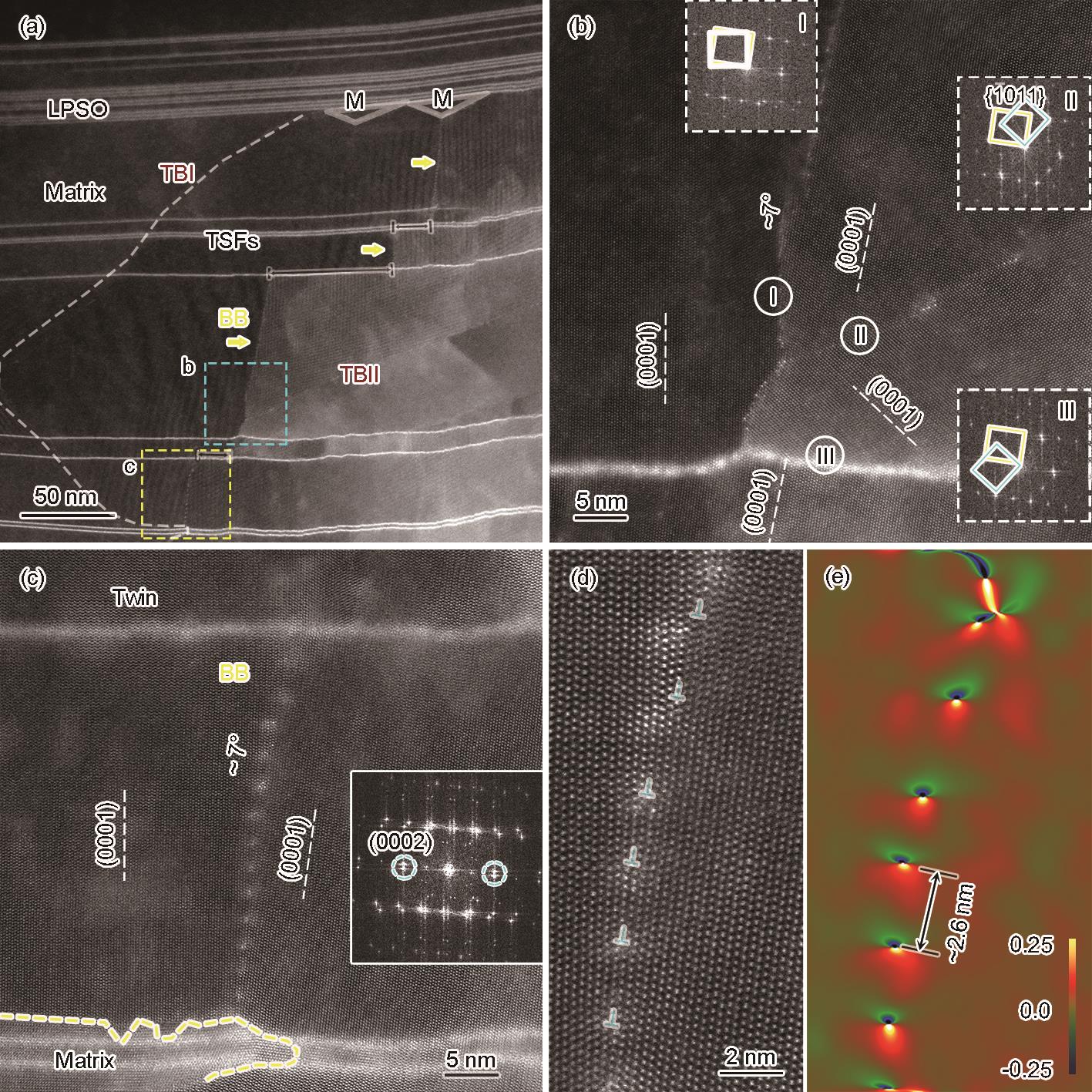
(a) high-magnification HAADF-STEM image showing the twin-induced BB boundary within the LPSO structures, where the TB is delineated by a white dashed line
(b) enlarged image of cyan rectangle framed area showing that the BB coexists with {
(c) enlarged image of yellow rectangle framed area indicating that the BB (~7°) is connected with TB, and the FFT image is inserted
(d) a set of dislocations are displayed at the BB boundary generated by masking (0002) reflections (shown by the cyan dashed circles) of the two crystals
(e) geometric phase analysis (GPA) further confirming the position of dislocation cores (The colour bar indicates change in strain intensity from -0.25 (compressive) to 0.25 (tensile))