异质纳米结构金属强化韧化机理研究进展
Progress in Strengthening and Toughening Mechanisms of Heterogeneous Nanostructured Metals
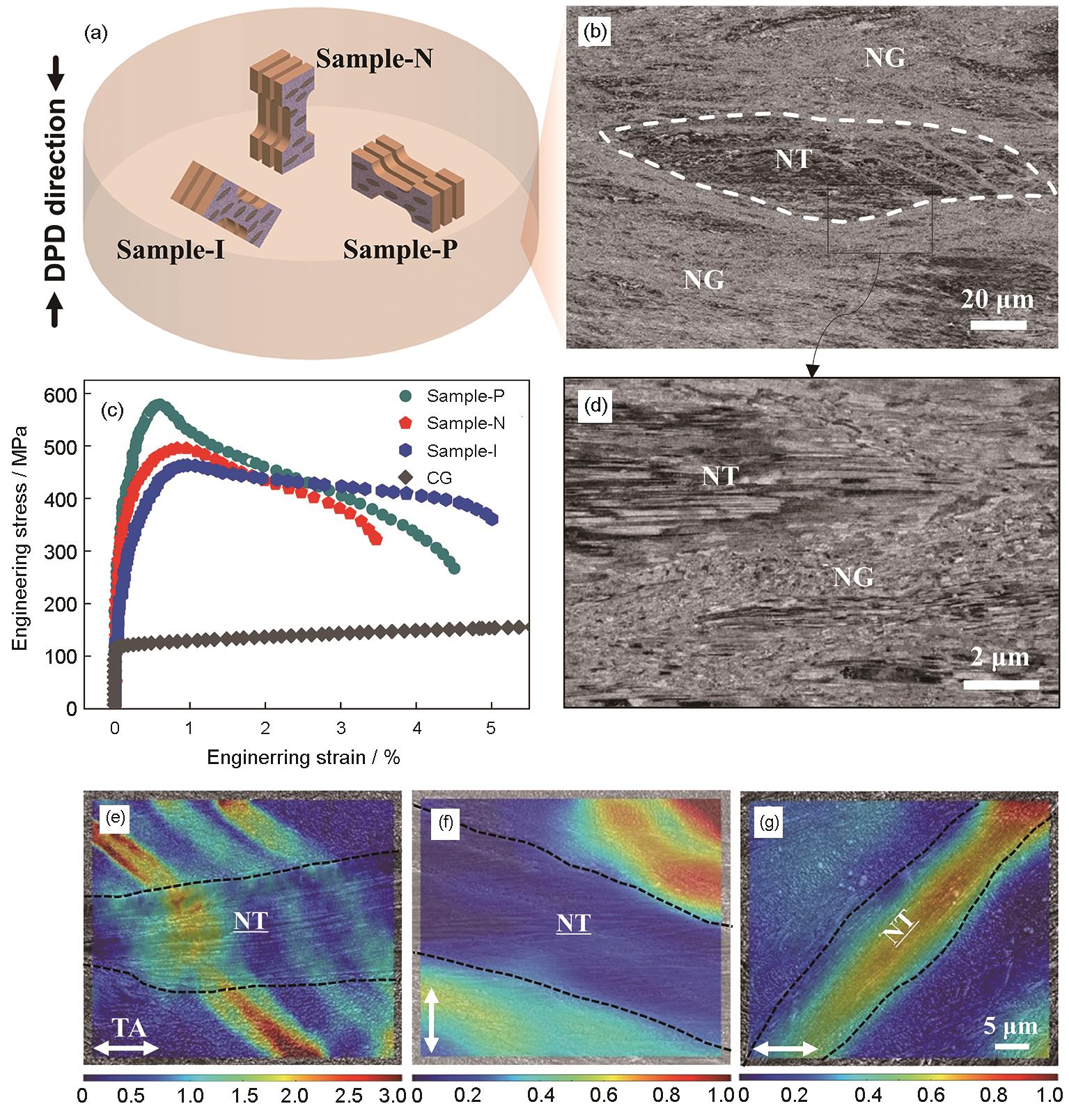
(a) schematic of the tensile specimens in the DPD disc and their orientations relative to the twin boundaries (TBs), i.e., parallel, normal, and 45° inclined to TBs, hereafter referred to as sample-P, sample-N, and sample-I, respectively (b, d) typical cross-sectional microstructures of DPD Cu, showing the nanotwins (NT) in the form of bundles embedded in a matrix of nanograins (NG) (c) tensile engineering stress-strain curves for the DPD processed heterogeneous nanostructured Cu and the coarse-grained (CG) Cu serve as a counterpart for comparison (e-g) local strain fields in sample-P (e), sample-N (f), and sample-I (g) at applied strain of 1.0%. The nanotwinned regions are denoted as NT, where the underscore indicated the direction parallel to TBs. The black dash lines indicate the position of the NT/NG interfaces. The tensile axes (TA) are represented by the double-headed arrows